Such devices are used to create the required voltage in a specific node of an electrical circuit. This is necessary to ensure the functionality of regulators, filters, and sensors. Using the information below, you can learn how to calculate the voltage drop across a resistor yourself and using automated calculators. Illustrative examples and qualified recommendations will be useful in practice.
Voltage divider circuits
Resistive voltage divider
In general, devices of this type perform a conversion according to the formula U out = U in*K, where:
- Uin (out) – voltage at the input and output, respectively;
- K is a correction factor indicating the transmission capabilities of the node.
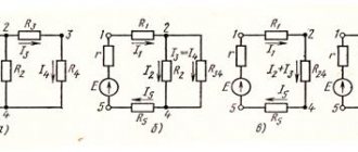
If we take the first example from Fig. above, to clarify the essence of the processes, Kirchhoff’s second law is suitable. In accordance with this rule, the total voltage value across series-connected resistors will be equal to the sum of the EMF on each element. Since the current does not change in a closed loop, Ohm's law can be used for calculation:
U (voltage) = I (current) * R (electrical resistance)
The lower part of the circuit (arm) is used to obtain the required change in the input parameter.
How to find voltage using the formula
People interested in electricity and physics are always concerned with the question of how to find voltages if other characteristics are known. It can be found through many formulas: in accordance with Ohm's law, through the work of current, by adding all the voltages in an electrical circuit and in a practical way - using a voltmeter. How to calculate the indicator using the latter method was described above.
Important! In series-connected circuits, the total voltage is the sum of the values of each load. In a parallel connection, the total voltage is equal to the value of each bulb, which is also equivalent.
What formulas are used to calculate voltage through work and the current strength itself are taught in physics lessons, since these quantities are considered basic. The work done by the current is equal to the product of voltage and charge: A = U*q. Also, A = U*I*t is derived from this formula, since charge is the product of current and time. It follows from them that U = A/q or U = A/(I*t). In addition, one of the main ones is the voltage formula derived from Ohm’s law: U = R/I.
Important! Voltage can also be determined through the power of the electric current. The power [P] is equal to A/t, and since A = U*I*t, the final formula looks like P = (U*I*t)/t. Here t will be reduced, and P = U*I will remain, from which it follows that U = P/I.
Types and principle of operation
This publication discusses in detail the resistive voltage divider. This assumes linearity of the circuit characteristics. In such circuits, the calculation of resistance to lower the voltage to the required level is simplified. When a DC source is connected, the voltages are divided in direct proportion to the values of the electrical resistances of the lower and upper arms.
Circuits with reactive characteristics
What is a voltage stabilizer
If you create a similar circuit with capacitors, then to maintain normal functionality you will have to apply a sine wave to the input. In this case, voltage distribution will also be carried out on elements with capacitive characteristics. However, this process must be considered in dynamics, taking into account the frequency and the corresponding change in amplitude. A similar technique is used when working with inductive components.
Reactance values:
- Rc=1/(2*f*π*C);
- RL=2*f*π*C.
The formulas show that the resistance of the capacitor/coil is inversely (directly) proportional to the capacitance/inductance. The values of the elements for dividing the voltage are selected accordingly.
In the presented examples, the internal load resistance is assumed to be infinitely large. For real calculations, more complex formulas with correction factors are used. The actual complex characteristics of the circuits are taken into account.
For your information. In voltage stabilizers and some other devices, the resistance of the divider arm has nonlinear parameters.
Calculation of voltage divider on resistors
Voltage stabilizer 12 volts
In the simplest circuit, two resistors are used. If necessary, the number of components is increased to provide stepwise adjustment. To calculate the voltage divider, you do not need to use an online calculator. The detailed instructions below will help you get an accurate result on your own in a few minutes.
Voltage divider formula
For example, certain values are taken:
- Input DC voltage (Uin) – 20 Volts;
- The resistances of resistors R1 and R2 are 20 and 50 kOhm, respectively.
Self-calculation of a resistive divider online
A halving of the input voltage will be achieved with equal values of resistor resistance. For this example, you will have to calculate the proportion using the formula of Ohm's law:
I=Uin/ (R1+R2)
By substituting the original values, it is easy to find out the strength of the current flowing through a given series circuit:
20/ (20,000 + 50,000) = 0.000286 A
The voltage drops on individual elements will be:
- UR1 = 0.000286 * 20,000 = 5.72 V;
- UR2 = 0.000286 * 50,000 = 14.3 V.
To directly calculate the voltage on the working arm, you can use the formula:
UR2 = Uin * R2/ (R1+R2)
Calculation of the voltage divider using an online calculator
The corresponding programs are offered to visitors by “Soldering Iron” and other specialized sites for free and without registration. In the standard form, fill in the “windows” with the voltage at the input and output. After confirmation, a calculation is automatically performed, displaying the values of the electrical resistances of the resistors and the dissipated powers.
As is clear from the example, the basic formulas are not particularly complex. However, automated online calculation of a voltage divider using resistors allows you to perform multiple theoretical experiments with minimal time. Such a tool is useful for accurately determining the main parameters of the divider.
Calculation table
| Input voltage Uin, V | Email resistance, Ohm | Power dissipation, W | Output voltage Uout, V | ||
| R1 | R2 | R1 | R2 | ||
| 12 | 1000 | 2000 | 0,016 | 0,032 | 8 |
| 12 | 50000 | 4545 | 0,00242 | 0,00022 | 1 |
| 12 | 50000 | 550000 | 0,00002 | 0,00022 | 11,5 |
| 12 | 100 | 200 | 0,16 | 0,32 | 8 |
The given figures demonstrate that in order to significantly reduce Uout, resistance R1 must be significantly greater than R2. Inverse proportions are used for approximately equal voltages at the input and output.
The total losses in the circuit are determined by the power dissipation. The lower the resistance, the stronger the current. For independent calculations, use the formula:
P=I2*R.
Input impedance
In a block diagram, the block input is located on the left, the output is on the right.
Rice. 3 - Inputs and outputs in block diagram
As expected, this block is used in some kind of radio-electronic device and performs some function. This means that some input voltage Uin from another block or from a power source will be supplied to its input, and voltage Uout will appear at its output (or will not appear if the block is the final one).
Rice. 4 - Input and output voltage
But since we apply voltage to the input (input voltage Uin), therefore, this block will consume some current Iin.
Rice. 5 - Input current
What does Iin depend on? In general, what does the current strength in a circuit depend on? Let's remember Ohm's law for a section of a circuit:
This means that our current strength depends on voltage and resistance. Let's assume that our voltage does not change, therefore, the current strength in the circuit will depend on. RESISTANCE. But where can we find it? And it hides in the cascade itself and is called input impedance .
Rice. 6 - Input impedance
That is, having disassembled such a block, we can find this resistor inside it? Of course not. It is a kind of resistance of radioelements connected according to the circuit of this block.
Input impedance measurement
As we know, each block is supplied with some kind of signal from the previous block, or it can even be powered from the network or battery. What can we do?
- Measure the voltage Uin supplied to the unit.
- Measure the current Iin that the unit consumes.
- Using Ohm's law, find the input resistance Rin.
If your input resistance is very high, in order to measure it as accurately as possible, use this circuit.
Rice. 7 - Input resistance measurement
You and I know that if our input resistance is large, then the input current in the circuit will be very small (from Ohm’s law).
We denote the voltage drop across resistor R as
From all this we get.
When we make these measurements, keep in mind that the voltage at the generator output should not change!
So, let's calculate what kind of resistor we need to choose in order to measure this input resistance as accurately as possible. Let's assume that we have input resistance Rin = 1 MOhm, and the resistor is R = 1 KOhm. Let the generator produce a constant voltage U=10 V. As a result, we get a circuit with two resistances. The voltage divider rule states: the sum of the voltage drops across all resistances in the circuit equals the emf of the generator.
Application
The use of such circuitry in practice is demonstrated by the following examples. To calculate electrical parameters without taking into account load resistance, the manual and automated methods discussed above are suitable.
Potentiometers
If the resistor is equipped with a slider and a corresponding drive, the resistance can be changed smoothly. This solution allows you to more accurately change the output voltage compared to discrete circuits. The main disadvantage is the complexity of the design, which, in addition to increasing the cost, reduces reliability. It is necessary to ensure the tightness of the working area to prevent contamination and prevent corrosion processes.
Potentiometer circuit diagram
Resistive sensors
This option takes advantage of the ability of some materials to increase/decrease electrical resistance under the influence of temperature, light flux, and other external influences. A sensor created on the basis of these principles is installed in the divider arm. Changes in the corresponding parameters are monitored by the output voltage level.
Feedback circuits in amplifiers
This solution provides the required gain. In the diagram below, this parameter will never be lower than one. To increase the conversion level, increase the value of resistance R2 relative to R1.
Voltage divider in the feedback circuit
The simplest electrical filters
For filtering, resistors R1 or R2 are replaced with a capacitor. In the first version, the device allows high-frequency components to pass through unhindered. When the frequency decreases to a certain level, the reactance increases, preventing the passage of current. Similarly, changes are made in the lower arm of the divider in order to cut off low frequencies.
Voltage amplifier
A variable resistor changes the signal level to obtain the required sound volume. Such devices use elements with a logarithmic characteristic of resistance change, which corresponds well to the natural mechanism of perception by the human hearing organs.
Parametric voltage stabilizer
In such circuits, the lower arm of the divider can be created using a zener diode. Its current-voltage characteristics are chosen in such a way that the output voltage maintains the desired value when the input parameters change.
Limitations in use
From the calculation examples given in the table, it is clearly seen how losses increase significantly as the circuit resistance decreases. Energy is wasted to heat the environment. With high power dissipation, it is necessary to use forced cooling systems and passive radiators.
The above calculations did not take into account the load. If you add resistance corresponding to real conditions, additional losses are generated in the parallel circuit.
Effect of Load Resistance
The first part of the figure shows a typical divider providing an output voltage of 5 V. With a current consumption of 0.01 A, the load resistance will be 0.5 kOhm. Using the calculation formula for a parallel circuit, it is easy to find out the total value of R = 1/(1/R2 + 1/Rload) = 0.25 kOhm. This addition will reduce the planned value of Uout to 3.46 V.
By decreasing R2 you can reduce the harmful effect on the output voltage (4.75 V). However, this method, shown in the second part of the figure, is accompanied by significant energy losses. The current will flow through the area with less resistance, not performing useful functions. In this example, you must select R1, which is rated at at least 2 W to ensure reliable operation of the device.
Completeness
The complete set of dividers is shown in Table 3
Table 3
Modification designation | Name | Quantity, PC |
| DNV-80 A | High-voltage voltage divider DNV-80 A RUKYU.411522.005 | 1 |
| Connecting cable RUKYU.685661.001 | 1 | |
| Operating manual RUKYU.411522.005 RE | 1 | |
| RUKYU box. 321213.001 | 1 | |
| DNV-80 I | High-voltage pulse voltage divider DNV-80 I RUKYU.411522.005 | 1 |
| Connecting cable RUKYU.685662.005 | 1 | |
| Operating manual RUKYU.411522.005 RE | 1 | |
| RUKYU box. 321213.001 | 1 |