What is a phase in electricity - definition of the concept
Phase in electricity is the colloquial name for a wire that is energized relative to another, which is called zero. This name comes from the fact that the current generated at substations and supplied to houses is variable, that is, the EMF created at substations have the same frequency (for Russia and the CIS countries it is 50 Hz), but are shifted relative to each other friend in time at a certain phase angle. Houses are usually supplied with all three phases and it does not matter which phase your apartment is connected to.
Figure 1. Electrics and electricity - schematic representation of phase, zero and ground
In Fig. 1 is a schematic diagram of the flow of electric current into the apartment from the general system. The letters $L1$, $L2$, $L3$ denote phases 1-3, and the letter $N$ denotes the neutral wire.
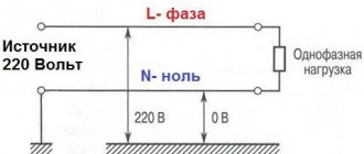
In Fig. Figure 2 shows a schematic connection of current to the apartment from the transformer, the letter $L_T$ denotes the phase on the transformer, the letter $L$ denotes the phase in the apartment, and the letter $R_H$ denotes a connected electrical appliance that has some resistance $R_H$.
There are 2 wires coming from the transformer, one is the so-called phase wire with voltage, and the other is the neutral wire, from which the grounding is carried out by placing the contact in the ground. There are other sources of grounding besides the ground itself; in these figures, grounding is indicated by the letters $Zml$.
In Fig. Figure 3 shows the case when the neutral grounded wire is not routed into the apartment from the substation, but is grounded directly in the apartment. The voltage $L_T$ between zero and phase will be the same for Figures 2 and 3, however, it is not recommended to ground the voltage from the transformer directly in the apartment.
Phase and zero: concepts and differences
There is such a thing as tension. This word means the degree of electric field strength at a given point or circuit. Otherwise it is called potential. In very simple words, this is a kind of piston that gives an impetus to electrons so that they pass through the wires and light a light bulb in a chandelier.
In the common circuit (phase zero), the one that comes to the chandelier or socket, there are two wires. One of them is a phase. It is this wire that is live. A phase in electrical engineering is comparable to a positive in a car - it is the main power supply for the network.
You may be interested in: Features of copper conductivity
Phase, neutral, ground in the socket
Zero is a wire that is not energized (this is exactly what distinguishes zero from phase). It is not overloaded during the power take-off process, but, nevertheless, electric current also flows through it, only in the direction opposite to the phase one. In the absence of voltage, it is safe in terms of electric shock to a person.
Types of current
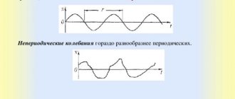
The current can be constant or alternating. A current that does not change in value over a period of time is a current of constant value. A current, the magnitude of which, like the direction, changes over time, is called variable.
Constant current sources - batteries, batteries, and so on. Alternating current is “suitable” for household and industrial sockets in homes and businesses. The main reason for this lies in the fact that this type of current is much easier to obtain physically, convert to different voltage levels, and transmit through electrical wires over vast distances without significant losses.
Single phase current
Alternating current, which is obtained by rotating a conductor or a system of conductors connected into one coil in a magnetic flux, is called single-phase alternating current . As a rule, 2 wires are used to transmit single-phase current. They are called phase and zero, respectively. The voltage between these wires is 220 V.
Single phase power supply. Single-phase current can be supplied to the consumer in two different ways: 2-wire and 3-wire. In the first (two-wire) one, two wires are used to supply single-phase current. One carries phase current, the other is intended for the neutral wire. Thus, power supply is supplied to almost all houses built in the former USSR. In the second method, to supply single-phase current , another wire is added. This wire is called grounding (PE). It is designed to prevent electric shock to a person, as well as to drain leakage currents and prevent devices from breaking.
Two-phase current
Everyone understands the concept of two-phase electric current - the merging of two single-phase currents that have a phase shift to each other. The shift angle can be Pi2 or 90°.
Why is zero needed in electricity?
Zero completes the electrical circuit. Without this wire, there can be no electric current in the circuit, which provides the power to power household appliances. Essentially, the neutral wire is ground.
Where does zero come from in the electrical network?
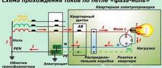
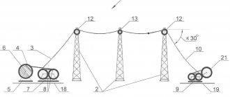
The zero originates from the complete 6(10)/0.4 kV transformer substation, where the transformer is connected to the ground loop by its zero bus. Initially, it is the earth that is a conductor with zero potential, and this is why many people confuse zero with earth. The overhead power line (overhead power line), leaving the transformer substation, has 4 wires - 3 phases and a neutral, which at the beginning of the line is connected to the neutral of the transformer. Along the overhead line, re-grounding is carried out through one support, which additionally connects the zero of the line to the ground, which provides a more complete connection of the “phase-zero” circuit so that the end consumer has at least 220V in the outlet.
Phase, neutral and ground in the wire
Why is zero needed?
The main purpose of the neutral wire is to close the circuit to create electric current for the operation of any electrical appliance. After all, in order for current to appear, a potential difference between the two wires is necessary. This is why it is called zero because the potential on it is zero. Hence the voltage level is 220V - 230V.
Cable color marking
This is one of the simplest methods. To determine what phase and zero are by color, you need to clearly know which shades correspond to what. You can use information about the standards adopted in the country.
It's no secret that each wire has an individual color. Therefore, recognizing zero should not be a particular problem. The knowledge gained will allow you to easily cope with the installation of a lighting fixture or installation of an outlet. This method is especially relevant for new buildings. After all, there, as a rule, wires are laid by experienced specialists who strictly comply with norms and standards. The IEC 60446 standard, adopted on the territory of the Russian Federation in 2004, strictly regulates the separation of phase, grounding and zero by color.
It is worth considering that:
- if the wire has a blue or blue-white tint, we can safely say that this is a working zero
- the protective zero is represented by cables in a yellow-green sheath
- other colors are characteristic of the phase. It can be red, brown, white or black. Other options are also possible.
This designation is successfully used in most cases. But if the wiring is old, or there are doubts about the professionalism of electricians, it is more advisable to use additional methods.
Household electrical wiring.
Initially, electricity is generated at a power plant. Then, through the industrial power grid, it enters the transformer substation, where the voltage is converted to 380 volts. The connection of the secondary windings of the step-down transformer is made according to the “star” circuit: three contacts are connected to the common point “0”, and the remaining three are connected to terminals “A”, “B” and “C”, respectively. For clarity, a picture is provided.
The combined contacts “0” are connected to the grounding loop of the substation. Also here the zero is split into:
- Working zero (shown in blue in the picture)
- PE conductor performing a protective function (yellow-green line)
The zeros and phases of the current from the output of the step-down transformer are supplied to the distribution panel of the residential building. The resulting three-phase system is distributed across panels in the entrances. Ultimately, a phase voltage of 220 V and a PE conductor, which performs a protective function, enters the apartment.
So, what is zero phase current ? A zero is a current conductor connected to the ground loop of a step-down transformer and serves to create a load from the current phase connected to the opposite end of the transformer winding. In addition, there is a so-called “protective zero” - this is the PE contact described earlier. It serves to drain current when a technical malfunction occurs in the circuit.
This method of connecting residential buildings to the city power grid has been proven for decades, but it is still not ideal. Sometimes malfunctions appear in the above system. Most often, they are associated with poor connection quality in a certain section of the circuit or a complete break in the electrical wire.
Phase and zero: their meaning in the power supply network
Electricity is supplied to consumer sockets from substations, which reduce the incoming voltage to 380 V. The secondary winding of such a transformer has a “star” connection - its three contacts are connected to each other at the “0” point, the remaining three outputs go to the “A” / “B” terminals "/"WITH".
The wires connected at point “0” are connected to “ground”. At the same point, the conductor is divided into “zero” (indicated in blue) and a protective “PE” cable (yellow-green line).
This model of wiring is used in all houses currently being built. It is called the “TN-S” system. According to this diagram, three phase cables and two indicated zeros are suitable for the distribution equipment of the house.
In houses, enterprises and buildings of old construction there is often no “PE” conductor and therefore the circuit turns out not to be five-wire, but four (it is designated as “TN-C”).
All electrical wires from the substations are connected to the panel, forming a three-phase system. Then there is a division into separate entrances. Each of the entrance apartments is supplied with only one phase voltage - 220 V (wires “O” / “A”) and a protective “PE” cable.
With this scheme, the entire load on the power supply system is distributed evenly, since on each floor of the house specific panels are wired and connected to a specific 220 V power line.
The supply voltage circuit is a “star”, which exactly repeats all the vector characteristics of the supply substation. When there are no consumers in the sockets, no current flows in this circuit.
This connection scheme has been worked out for years. It confirmed its right to use by being recognized as the optimal of all existing ones. However, in it, as in any device, mechanism or device, all kinds of breakdowns and malfunctions may periodically appear. As a rule, they are associated with poor quality electrical connections or complete cable breaks in some places in the circuit.
Consequences of phase or zero loss
This situation occurs quite often in home electrical networks. The main reason for its appearance may be poor contact or high loads, which leads to burnout of metal current-carrying elements. Knowing why zero is needed in electricity, which is called a phase, we can draw a conclusion about the possible consequences.
It doesn’t matter at all which of these two conductors is broken, the consumer connected to the faulty circuit will not work. The situation is similar with a wire break of any phase in the general house network.
In such a situation, all apartments connected to this line will be deprived of electricity. In this case, in the two remaining circuits there will be no problems with the operation of electrical appliances, only the current strength in the neutral conductor will increase.
With all these breaks, damage to household appliances is excluded.
If in one apartment the load on the network is low, and in another it is high, then, according to Ohm’s law, the second owner may experience serious problems; a voltage close to 380 V will be supplied to him. To avoid such troubles, special protective equipment is installed in switchboards. However, some apartment owners install additional devices to avoid premature failure of complex electrical appliances.
Understanding the concepts of neutral and phase conductors in electrical engineering is quite easy. Even a novice home master will succeed in this. However, it should be remembered that working with electricity can be life-threatening
To avoid serious trouble, you must always exercise extreme caution. At best, the consequence of an error will be the failure of electrical appliances, but electric shock is also possible
What happens in zero and phase when a wire breaks.
Line breaks quite often occur due to the fault of the craftsmen - they forget to connect a phase or zero. Such breakdowns are quite common. Also, quite often the process of zero burnout on the access panel occurs, for example, due to high load in the system.
If a break occurs in any part of the chain, the entire chain stops functioning, because it opens. In such situations, it does not matter at all which wire is damaged - phase or neutral. The same thing happens when there is a break between the distribution board of a high-rise building and the panel in the entrance. With such a gust, all consumers who were connected to this panel will be without electricity.
All the situations that we tried to describe above occur. They may seem complicated, but they pose no danger to humanity. After all, the break occurred in only one wire, so it is not at all dangerous.
A very alarming situation is when the contact between the ground loop at the substation and the middle point, to which all the voltage of the in-house panel is supplied, is lost.
It is in this embodiment that the electric current moves along the contours AB, BC, CA. The total voltage of these circuits is 380V. It is for this reason that a rather dangerous situation arises - one panel may have no voltage at all, because the owner will turn off all electrical appliances, and a very high voltage level will form on the other, about 380V. This can contribute to the failure of many devices, because they require a voltage of 220V.
Naturally, this situation can be avoided. There is a lot of inexpensive/expensive equipment that will protect your equipment from power surges. Such equipment also includes a voltage stabilizer. There are the following types of stabilizers:
- Single phase;
- Three-phase.
How to find zero and phase
At home, even without special instruments and devices, it is possible to determine in a regular outlet which of the two wires is a phase and which is a zero. In this case, an electric lamp or an indicator screwdriver is used.
Checking with an electric lamp
To find zero and phase, just take an ordinary socket with a light bulb and screw two wires into its regular places. Then connect one of these wires to the grounding blades in the socket, and the second to either of the two power connectors.
The phase connector will be the one to which the light bulb will light up when connected. This happens because, according to the Electrical Installation Rules (PUE), in the input electrical panel, the neutral wires of all sockets must be connected to the ground wires of the same sockets. A separate earth bus must be connected to a protective ground loop. This is what ensures the presence of a reliable zero in the entire energy supply chain of the house.
Note! It is permissible to carry out such procedures independently only in cases where there is nowhere to wait for qualified help, as well as in the event of an emergency (fire, short circuit, person under voltage). Do not forget that electric current is very dangerous. Don't risk your health and your life over a light bulb!
Indicator screwdriver
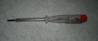
In order to determine the phase in an alternating current network with a voltage of 220V - 230V, you can use a household voltage indicator - an indicator screwdriver. It is sold in almost any hardware store and is (depending on the design) very inexpensive.
An example of a working indicator screwdriver
As a rule, such tools do not have instructions for use, so in order to avoid electrical injury, you should remember a few simple rules that apply to any tool that comes into contact with live parts:
- Use the tool only for its intended purpose (it is prohibited to use the voltage indicator - indicator screwdriver - as an ordinary screwdriver for tightening/unscrewing screws, self-tapping screws, screws, etc.)
- Before using the tool, you should carefully consider the condition of the insulation on the handle and tip (applicable to any screwdrivers, including indicator ones). Do not use the device under any circumstances if the insulating coating is chipped or missing altogether.
- It is necessary to check the functionality of indicator devices on electrical installations that are known to be energized (for example, in an extension cord into which a working electrical appliance is connected).
Screwdriver with insulated blade
If there is any doubt about the functionality of the indicator, it should be considered faulty and the electrical installation functional.
There are also more accurate and safer instruments for determining the presence of voltage in the network - these are multimeters, current clamps, volt-ampere phase meters (VAF) and others.
Multimeter
In everyday life, as a rule, simple multimeters are used. They are able to show the presence of voltage in the network and its value. It is much safer to use these devices to determine the phase, since their probes have a dielectric handle. The principle of determination is the same as in the case of a cartridge - it is enough to apply one probe to the ground contact of the socket, and place the second one on one of the two contacts of the socket.
Multimeter example
Important! Like traffic rules, electrical safety rules must be followed, because electric current is invisible, inaudible and intangible, and this is precisely why it is dangerous.
Electricity (according to Newton's second law) does not appear from nowhere and does not go to nowhere. It is produced, transported and consumed before our eyes. We need to know where it comes from, how it gets to us and in what form. Everyone should understand that in household use there are wires that can harm human health, and there are also those that are completely harmless, so a little knowledge and a minimum of instruments are needed to identify and distinguish between these wires. But it is better to trust any manipulations with electricity to a professional - a qualified specialist, in order to avoid disaster.
How to determine zero and phase on your own.
To determine the zero and phase of the current, there are special tester screwdrivers.
It works on the principle of passing low voltage current through the body of the person using it. The screwdriver consists of the following parts:
- Tip for connecting to the phase potential of the socket;
- A resistor that reduces the amplitude of the electric current to safe limits;
- An LED that lights up when there is a current phase in the circuit;
- Flat contact to create a circuit through the operator's body.
Zeroing in the apartment
This is the connection of the neutral cable with the neutral conductor of the electrical network and the device body. It is assumed that the procedure ensures faster disconnection of the device from the network when touching a dangerous place, if the voltage is above a certain threshold. But it is associated with an additional danger: if there is a zero break, all devices connected at that moment to the apartment’s network will have a phase (and not zero) on the surface, which creates a significant threat to the health of residents. Therefore, such installation work is strictly regulated.
Knowing what exactly is called a phase in an electrical network and how to detect it is extremely important when carrying out electrical installation work. Otherwise, there is a high risk of harming the health of the tenants or the condition of electrical appliances.
Secrets of home electrical wiring
At home, people mainly deal with alternating current. A typical circuit has three cores. Through the working one, electricity enters the network, and through the second one it returns back. The third serves for grounding.
Even to use a home network, you need to understand some basics:
- The grounding conductor has no load. It functions as a fuse against electric shock. It also removes “excess” electricity.
- The return core is called zero. If the system is installed correctly, there is no voltage on this wire either. But if there are errors in the wiring, its occurrence cannot be ruled out.
- The work wire is especially dangerous to handle. You need to be extremely careful with it, even when the network is turned off.
- Household appliances (except those that run on batteries) turn on only when the entire circuit is properly closed. Therefore, it is necessary to determine the required cable for each point during installation.
Networks in modern apartment buildings are now quite reliable. But even in such conditions, it is easy to answer the question of why you need to know about the intricacies of working with wiring - this will be useful both in case of problems with household appliances and when carrying out serious repairs.
How to distinguish phase, zero, ground
The easiest way to determine the purpose of the conductors is by color marking. In accordance with the standards, the phase conductor can have any color, the neutral can be blue, and the ground can be yellow-green. Unfortunately, when installing electrics, color coding is not always observed. We must not forget the likelihood that an unscrupulous or inexperienced electrician can easily confuse phase and zero or connect two phases. For these reasons, it is always better to use more precise methods than color coding.
You can determine the phase and neutral conductors using an indicator screwdriver. When the screwdriver comes into contact with the phase, the indicator will light up, as electric current passes through the conductor. Zero has no voltage, so the indicator cannot light up.
You can distinguish zero from ground using a dial tone. First, the phase is determined and marked, then with a continuity probe you need to touch one of the conductors and the ground terminal in the electrical panel. Zero will not ring. When you touch the ground, a characteristic sound signal will be heard.
Determination of phase-zero loop resistance
To ensure the normal functioning of electrical appliances and check machines, it is necessary to periodically measure the resistance of the phase-zero loop. Because the primary causes of breakdowns of lighting devices are network overloads and short circuits. Measuring resistance allows you to quickly identify a malfunction and prevent a similar situation.
Not everyone knows what the concept of a “phase-zero loop” is. This phrase hides a circuit formed as a result of connecting the neutral wire located in a grounded neutral. The closure of this electrical network forms a phase-zero loop.
Resistance in this circuit is measured using the following methods:
- drop in voltage level in a disconnected circuit
- a drop in voltage level due to the resistance of an increasing load
- using a professional tool to interpret the short circuit in the circuit
The second method is used most often, as it is convenient, the ability to quickly measure resistance, and also safe.