Reinforced concrete power transmission line supports - classification by purpose
The classification of reinforced concrete supports by purpose does not go beyond the types of supports standardized in GOST and SNiP. Read in detail: Types of supports by purpose, but here I will briefly remind you.
Intermediate concrete supports are needed to support cables and wires. They are not subject to longitudinal or angular tension loads. (marking P10-3, P10-4)
Anchor concrete supports provide support for wires during their longitudinal tension. Anchor supports must be installed at the intersection of power lines with railways and other natural and engineering barriers.
Corner supports are placed at the turns of the power line route. At small angles (up to 30°), where the tension load is not large and if there is no change in the cross-section of the wires, angular intermediate supports (IP) are installed. At large rotation angles (more than 30°), corner anchor supports (CA) are installed. At the end of the power line, anchors, also known as end supports, are placed (A). For branches to subscribers, branch anchor supports (OA) are installed.
Installation Basics
When the hole is ready, you can begin to install the pillars themselves. To do this, you will definitely have to use special equipment.
Kawabanga! Lawn grate for parking made of concrete
In this order, work is carried out to install intermediate supporting reinforced concrete pillars:
Reinforced concrete supporting structures differ from wooden ones in their strength and increased resistance to negative environmental influences. But their installation is impossible without the use of special equipment, since they are heavy.
Marking of concrete supports
It is worth focusing on the markings of the supports. In the previous paragraph I used the markings for the 10-2 supports. Let me explain how to read the markings of the supports. Reinforced concrete supports are marked as follows.
- The first two letters indicate the purpose of the support: P (intermediate) UP (intermediate corner), UA (corner anchor), A (anchor-end), OA (branch support), UOA (corner branch anchor).
- The second number means for which power transmission line the support is intended: the number “10” is a 10 kV power line.
- The third number after the dash is the standard size of the support. The number “1” is a 10.5 meter support, based on the SV-105 pillar. The number “2” is a support based on the SV-110 pillar. Detailed standard sizes are in the tables at the bottom of the article.
Reinforced concrete supports
In the industrial manufacturing process, they are the most optimal option for overhead lines both up to 1000 V and above 1000 V. The use of reinforced concrete supports dramatically reduces operating costs, since they practically do not require repairs. Currently, almost everywhere, reinforced concrete supports are used in the construction of overhead lines of 6-10 kV and up to 110 kV. They are especially widespread in urban networks up to and above 1000 V. Reinforced concrete supports can be made either monolithic (cast) or in the form of assemblies, which are assembled directly at the installation site. Their strength depends on the method of concrete compaction, of which there are two - centrifugation and vibration. When using the centrifugation method, a good density of concrete is obtained, which subsequently has a good effect on the finished product.
On overhead power lines, special anchor, corner, end, and intermediate supports are used.
Installation of concrete supports
Calculation of supports is carried out by SNiP 2.02.01-83 and “Guide to the design of power lines and power line foundations...”. The calculation is based on deformation and bearing capacity.
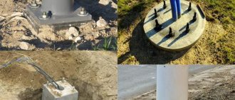
To secure an intermediate support of type P10-3(4), you need to drill a cylindrical pit with a diameter of 35-40 cm, to a depth of 2000-25000 mm. An installation bolt is not needed for such a support.
Anchor corner and anchor branch supports are usually mounted with installation crossbars. Please note that the crossbars can be placed on the lower edge of the support and strut, buried in the ground and/or on the upper edge of the support, along the top of the pit. The crossbars provide additional stability to the support. The depth of installation of the support depends on the freezing of the soil. Usually 2000-2500 mm.
Classification of supports
Lecture No. 11
Topic: SUPPORTING STRUCTURES.
(lecture – 1 hour)
Classification of supports
Contact network supports, depending on the purpose and nature of the loads taken from the catenary wires, are divided into intermediate, transition, anchor and fixing.
Intermediate supports carry loads from the mass of catenary wires and additional loads on them (ice, frost) and horizontal loads from wind pressure on the wires and from changes in the direction of wires on curved sections of the track.
Transitional supports are installed in places where the anchor sections of catenary suspensions and air switches connect and take loads similar to intermediate supports, but from two catenary suspensions. The transition supports are also affected by forces from changing the direction of the wires when they are routed to the anchorage and on the arrow curve.
Anchor supports can only carry loads from the tension of the wires attached to them or, in addition, carry the same loads as intermediate, transition or fixing supports.
The fixing supports do not bear loads from the mass of the wires and perceive only horizontal loads from changes in the direction of the wires on curved sections of the track, on air switches, when retreating to anchorage and from wind pressure on the wires.
There are also supports for supply and suction lines and special supports. The supports of supply and suction lines, in accordance with the classification of supports adopted in power transmission lines, are divided into intermediate, corner, anchor (wires are anchored on both sides) and end (wires are anchored on one side of the support). Special supports are designed for installing sectional disconnectors or any other equipment.
According to the type of contact network supporting devices mounted on supports, they are distinguished:
cantilever supports with catenary suspension mounted on the console of one, two or several tracks;
supports with a rigid crossbar, or, as they are called, crossbars or portals, with fastening of contact suspensions of electrified tracks on a rigid crossbar (crossbar);
supports with a flexible crossbar with fastening on it the contact suspensions of the electrified tracks covered by this crossbar.
Depending on the material, the supports can be reinforced concrete, metal and wood. The use of reinforced concrete prestressed supports made from centrifuged concrete provides a significant reduction in metal consumption for the manufacture of supports. Installing reinforced concrete supports is more difficult than metal ones, since they are much heavier and require more careful handling during transportation and installation due to the fragility of concrete.
Reinforced concrete supports are most widely used; they are used as intermediate, transitional and anchor cantilever supports, as well as fixing supports and racks of rigid crossbars.
Reinforced concrete cantilever supports and racks of rigid crossbars can be inseparable (solid) with a foundation part for direct installation in the ground, or separate, installed on separate foundations. In terms of material consumption, labor intensity of manufacturing and installation, undivided supports are preferable. Metal supports in Kazakhstan are used only as supports for flexible crossbars, supply and suction lines for two track consoles and anchor self-supporting (without guy wires) supports. If the necessary feasibility studies are available, metal supports are also installed as cantilever intermediate, transition and anchor supports.
Fig. 11.1 Unified reinforced concrete cantilever supports of a contact network 13.6 m long with a foundation part (a) and 10.8 m long on a three-beam glass foundation (b):
UOF – conditional edge of the foundation; OF – foundation edge; VGR – top of the rail head
Wooden supports of various types are installed only as temporary support structures for the contact network.
For contact networks, as a rule, standard supports are used, differing in purpose and design.
The height of the supports - the distance from the top (VOF) or conditional (UOF) edge of the foundation to the top of the support - is selected depending on the height of the suspension of the contact wire and the supporting cable of the chain hangers, the design of the supporting devices, the location of the lines supplying the automatic blocking devices on the contact network supports ( VL SCB).
The shape and dimensions of the cross-section of the supports depend on the standard bending moment (kN∙m) relative to the upper or conventional edge of the foundation, and for cantilever supports - also on the standard bending moment relative to the heel of the console.
The height of the cantilever reinforced concrete supports is taken to be 9.6 m; the same height of supports is used as racks of rigid crossbars. In this case, the length of the undivided supports, taking into account the foundation part, is 13.6 m (Fig. 11.1, a), and the length of the separate supports, taking into account their installation in a glass foundation, is 10.8 m (Fig. 11.1, b) .
Metal supports for flexible crossbars are made with a height (length) of 15 and 20 m. For double-track consoles, metal supports with a height of 13 m are installed.
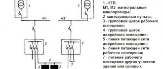
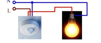
Grounding of concrete supports
Thanks to the design of the support posts, grounding the supports is very convenient. In the racks of SV supports, in the factory during their manufacture, metal reinforcement 10 mm in diameter is installed at the top and bottom of the rack. This reinforcement runs inextricably along the entire length of the rack. It is this reinforcement that serves to ground reinforced concrete supports.
Especially for the site “Electrics. Plumbing"
Tables of all types of concrete supports
©Elesant.ru
Other articles in the section: Overhead power lines
- Types of power transmission line supports by material
- Types of supports by purpose
- Overhead power lines with SIP wires
- Wooden supports for overhead power lines
- Reinforced concrete power transmission line supports
- Reinforced concrete power transmission line supports
- Power line support structures
- Tension of overhead power line wires
- SIP installation mistakes that should not be made
- Preparatory work for installation of overhead power lines
Features of lighting poles and power lines
It is no secret that power lines can be cable (buried in the ground) or overhead. Special reinforced concrete light supports have found widespread use in the construction of overhead power lines.
The basis of such structures is a centrifuged or vibrating rack, made using dense heavy cement mortars reinforced with welded metal structures.
Important: Structures erected using centrifuged racks (used for the construction of 35-110 kV power lines) are characterized by particular strength and durability.
Power line supports, in addition to centrifuged and verified racks, may consist of the following structural elements:
Installation of reinforced concrete supports in the ground is carried out by installing the structure in a pre-drilled cylindrical pit, followed by filling the sand and gravel mixture into the resulting cavities.
In order to ensure the necessary strength of the installation of the structure on soft soils, the underground part of the overhead line supports is strengthened by means of crossbars secured with half-clamps. To fasten suspended metal structures, clamps or through bolts are used.
Main characteristics
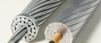
Reinforced concrete supports are made using high-quality concrete reinforced with rolled wire and reinforcing bars.
Among the main advantages of these structures, the following qualities should be noted:
Main varieties
In addition to the fact that reinforced concrete lighting poles are widely used, poles for power lines are used.
Such structures are divided into the following categories:
- Intermediate type supports
are used when constructing straight sections of overhead line routes.
In the photo - intermediate type pillars
Such structures are not designed for loads directed along power lines and are used exclusively for the installation of wires and fixing cables. Today, about 80% of all power lines are installed on.
In the photo - anchor posts
- Corner supports
are installed in those areas where the route changes its direction. Pillars of this type bear the resulting loads of the gravity of the wires from the intersupport adjacent spans.
- An end support
is a type of anchor post.
Such structures are located mainly at the beginning and end of power lines. Structures of this type are designed for one-sided loads.
- Special purpose supports
are used to perform special tasks.
Kawabanga! Panel apartments: pros and cons
Design features
In accordance with the structural features, reinforced concrete supports of overhead lines are divided into the following categories:
- portal with guy wires;
- portal with internal connections without guy wires;
- single- and multi-post with guy wires;
- single and multi-post without guy wires.