How to check cable insulation with a megohmmeter
The resistance of a cable's insulating layer is one of the most important parameters of its performance. If you bought a cable and it was stored in a warehouse for some time, do not think that its insulation will be the same as when you bought it. Insulation can deteriorate both under unsatisfactory storage conditions and during operation and installation. In order to identify all possible problems, the cable insulation is checked with a megohmmeter.
Preparatory work
The cable under test must be prepared before testing.
For this:
- ⚡check that there is no voltage on the cable cores
- ⚡there may be induced or residual voltage on long cables. Therefore, before each measurement, using a separate piece of wire or portable grounding, wearing dielectric gloves, you must touch the core and the grounded housing or grounding circuit to remove this charge;
- ⚡disconnect the cable from the connected equipment. This must be done so that when checking the cable insulation with a megohmmeter, only the cable itself is involved in the test, without the equipment or machines to which it is connected. Disconnection must be done on both sides of the cable. Sometimes this is not done to speed up work. First, a measurement is taken, and if it shows a negative result, then only after that the wires are pulled back.
Working with a megohmmeter
During testing, the megohmmeter produces a very high voltage - 500 V, 1000 V, 2500 V. In this regard, measurements must be taken very carefully.
At enterprises, persons with an electrical safety group of at least 3 are allowed to work with the device. Before taking measurements with a megohmmeter, the circuits being tested are disconnected from the power supply. If you are going to check the condition of the wiring in a house or apartment, you need to turn off the switches on the panel or unscrew the plugs. Then turn off all semiconductor devices.
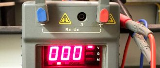
One of the options for modern megaohmmeters
If you check the socket groups, remove the plugs of all devices that are included in them. If the lighting circuits are checked, the light bulbs are unscrewed. They will not withstand the test voltage. When checking the insulation of the motors, they are also completely disconnected from the power supply. After this, grounding is connected to the circuits being tested. To do this, a stranded wire in a sheath with a cross-section of at least 1.5 mm2 is attached to the “ground” bus. This is the so-called portable grounding. For safer operation, the free end with the exposed conductor is attached to a dry wooden holder. But the bare end of the wire must be accessible so that it can touch wires and cables.
Requirements for ensuring safe working conditions
Even if you want to measure the cable insulation resistance at home, before using a megohmmeter you should familiarize yourself with the safety requirements. There are several basic rules:
- Hold the probes only by the insulated part limited by stops.
- Before connecting the device, turn off the voltage and make sure that there are no people nearby (along the entire route being measured, if we are talking about cables).
How to use a megohmmeter: electrical safety rules
The rules are not very complicated, but your safety depends on their implementation.
How to connect probes
The device usually has three sockets for connecting probes. They are located at the top of the instruments and are labeled:
- E - screen;
- L-line;
- Z - earth;
There are also three probes, one of which has two tips on one side. It is used when it is necessary to exclude leakage currents and clings to the cable screen (if there is one). There is an “E” on the double tap of this probe. The plug that comes from this outlet and is installed in the corresponding socket. Its second plug is installed in the “L” socket - line. A single probe is always connected to the ground socket.
Probes for megaohmmeter
There are stops on the probes. When taking measurements, grasp them with your hands so that your fingers reach these stops. This is a prerequisite for safe operation (remember about high voltage).
If you only need to check the insulation resistance without a screen, place two single probes - one in the “Z” terminal, the other in the “L” terminal. Using crocodile clips at the ends, we connect the probes:
- To the wires being tested, if you need to check the breakdown between the wires in the cable.
- To the core and the “ground”, if we check the “breakdown to ground”.
There is a letter “E” - this end is inserted into a socket with the same letter
There are no other combinations. The insulation and its breakdown are checked more often; working with the screen is quite rare, since shielded cables themselves are rarely used in apartments and private houses. Actually, using a megohmmeter is not particularly difficult. It is only important not to forget about the presence of high voltage and the need to remove the residual charge after each measurement. This is done by touching the ground wire to the wire you just measured. For safety, this wire can be secured to a dry wooden holder.
Measurement process
We set the voltage that the megohmmeter will produce. It is not selected randomly, but from a table. There are megohmmeters that work with only one voltage, and there are those that work with several. The latter, of course, are more convenient, since they can be used to test various devices and circuits. The test voltage is switched using a knob or button on the front panel of the device.
| Item name | Megohmmeter voltage | Minimum permissible insulation resistance | Notes |
| Electrical products and devices with voltage up to 50 V | 100 V | Must correspond to the passport data, but not less than 0.5 MOhm | During measurements, semiconductor devices must be bypassed |
| too, but with voltage from 50 V to 100 V | 250 V | ||
| too, but with voltage from 100 V to 380 V | 500-1000 V | ||
| over 380 V, but not more than 1000 V | 1000-2500 V | ||
| Switchgears, switchboards, conductors | 1000-2500 V | Not less than 1 MOhm | Measure each section of the switchgear |
| Electrical wiring, including lighting network | 1000 V | Not less than 0.5 MOhm | In hazardous areas, measurements are carried out once a year, in others - once every 3 years |
| Stationary electric stoves | 1000 V | Not less than 1 MOhm | The measurement is carried out on a heated, disconnected stove at least once a year. |
Before using a megohmmeter, we make sure that there is no voltage on the line using a tester or an indicator screwdriver. Then, having prepared the device (set the voltage and set the measurement scale on the dials) and connected the probes, remove the grounding from the cable being tested (if you remember, it is connected before starting work).
The next stage is to turn on the megohmmeter: on the electronic ones we press the Test button, on the pointer ones we turn the dynamo handle. We turn the switches until the lamp on the body lights up - this means the necessary voltage has been created in the circuit. In digital, at some point the value on the screen stabilizes. The numbers on the screen indicate the insulation resistance. If it is not less than the norm (the averages are indicated in the table, and the exact ones are in the product data sheet), then everything is normal.
How to take measurements with a megohmmeter
After the measurement is completed, we stop turning the knob of the megohmmeter or press the end of measurement button on the electronic model. After this, you can disconnect the probe and remove the residual voltage.
In short, these are all the rules for using a megohmmeter. Let's look at some measurement options in more detail.
Design and principle of operation of a megohmmeter
The aging of electrical wiring insulation, like any electrical circuit, cannot be determined with a multimeter. Actually, even with a rated voltage of 0.4 kV on the power cable, the leakage current through microcracks in the insulating layer will not be so large that it can be detected by standard means. Not to mention measuring the resistance of intact cable insulation.
In such cases, special devices are used - megohmmeters, which measure the insulation resistance between the motor windings, cable cores, etc. The principle of operation is that a certain voltage level is applied to the object and the rated current is measured. Based on these two values, the resistance is calculated according to Ohm's law for a section of the circuit (I = U/R and R=U/I).
It is typical that megohmmeters use direct current for testing. This is due to the capacitance of the measured objects, which will pass alternating current and thereby introduce inaccuracies in the measurements.
Structurally, megaohmmeter models are usually divided into two types:
- Analog (electromechanical) - old-style megohmmeters.
Analog megohmmeter - Digital (electronic) – modern measuring devices.
Electronic megohmmeter
Let's consider their features.
Electromechanical megohmmeter
Let's consider a simplified electrical circuit of a megohmmeter and its main elements
Simplified diagram of an electromechanical megohmmeter
Designations:
- A manual DC generator, a dynamo is used as such. As a rule, to obtain a given voltage, the rotation speed of the hand generator handle should be about two revolutions per second.
- Analog ammeter.
- An ammeter scale calibrated to indicate resistance measured in kiloohms (kOhm) and megaohm (MOhm). The calibration is based on Ohm's law.
- Resistance.
- KOhm/Mohm measurement switch.
- Clamps (output terminals) for connecting test leads. Where “Z” is the ground, “L” is the line, “E” is the screen. The latter is used when it is necessary to check the resistance against the cable shield.
The main advantage of this design is its autonomy; thanks to the use of a dynamo, the device does not require an internal or external power source. Unfortunately, this design has many weaknesses, namely:
- To display accurate data for analog instruments, it is important to minimize the mechanical impact factor, that is, the megohmmeter must remain stationary. And this is difficult to achieve by rotating the generator handle.
- The displayed data is affected by the rotational uniformity of the dynamo.
- Often the measurement process requires the efforts of two people. Moreover, one of them performs purely physical work - he rotates the handle of the generator.
- The main disadvantage of the analog scale is its nonlinearity, which also negatively affects the measurement error.
Note that in later analog megohmmeters, manufacturers abandoned the use of a dynamo, replacing it with the ability to operate from a built-in or external power source. This made it possible to get rid of characteristic shortcomings; in addition, the functionality of such devices has significantly increased, in particular, the voltage calibration range has expanded.
Modern analog model of megaohmmeter F4102
As for the principle of operation, it has remained unchanged in analog models and consists of a special gradation of the scale.
Electronic megohmmeter
The main difference between digital megohmmeters is the use of a modern microprocessor base, which can significantly expand the functionality of the devices. To obtain measurements, just set the initial parameters and then select the diagnostic mode. The result will be displayed on the information board. Since the microprocessor makes calculations based on operational data, the accuracy class of such devices is significantly higher than that of analog megohmmeters.
Separately, mention should be made of the compactness of digital megohmmeters and their versatility, for example, testing residual current devices, measuring ground resistance, phase/zero loops, etc. Thanks to this, comprehensive tests and all necessary measurements can be carried out with one device.
How to use a megohmmeter correctly?
To carry out testing, it is important to correctly set the measurement ranges and test voltage level. The easiest way to do this is to use special tables that indicate the parameters for the various objects being tested. An example of such a table is given below.
Table 1. Correspondence of the voltage level to the permissible insulation resistance value.
| Test object | Voltage level (V) | Minimum insulation resistance (MOhm) |
| Checking the electrical wiring | 1000,0 | 0,5> |
| Household electric stove | 1000,0 | 1,0> |
| RU, Electrical panels, power lines | 1000,0-2500,0 | 1,0> |
| Electrical equipment powered up to 50.0 volts | 100,0 | 0.5 or more depending on the parameters specified in the technical data sheet |
| Electrical equipment with rated voltage up to 100.0 volts | 250,0 | 0.5 or more depending on the parameters specified in the technical data sheet |
| Electrical equipment powered up to 380.0 volts | 500,0-1000,0 | 0.5 or more depending on the parameters specified in the technical data sheet |
| Equipment up to 1000.0 V | 2500,0 | 0.5 or more depending on the parameters specified in the technical data sheet |
Let's move on to the measurement technique.
Measuring the insulation of an asynchronous motor with a megohmmeter
Before measurements, turn off the power and remove the residual voltage. Then you need to gain access to the winding terminals. We attach one dipstick to the engine body. Make sure that the contact is with clean metal - you need to find an area without paint or rust. When checking, we connect the second probe to each of the windings (you also need to make sure that it is clean under the “crocodile”.
According to the table, asynchronous motors connected to a 220 V or 380 V network are tested at a voltage of 500 V.
Operating rules
A megaohmmeter is a dangerous device due to high voltage. Only a person who has knowledge and experience can work with it.
Only trained people who know safety precautions can start working with a megohmmeter. Work in electrical installations where the voltage is more than 1000 volts is carried out with permits, that is, a work permit. However, issuing a document for several works is not permitted. Also, working at a similar mains voltage is allowed for people who have the third and fourth electrical safety groups.
Note! Before starting, you need to check the integrity of the device. When working with the device, you must use dielectric gloves and under no circumstances touch live elements. After activity, it is necessary to remove the remaining charge by grounding.
Danger of overvoltage of the device
When working with a megohmmeter, there are specific features that you should pay close attention to. This is primarily due to the increased voltage of the device. The built-in generator has an output power sufficient not only to test insulation, but also to cause serious electrical injury. Therefore, in accordance with electrical safety rules, only trained and qualified specialists with at least 3rd tolerance group can use a megohmmeter.
During the measurement process, increased voltage covers the area being tested, as well as the terminals and connecting wires. Protection against this is provided by probes having a reinforced insulated surface. They are designed for installation on test leads. The ends of the probes are limited to a restricted area using safety rings. This prevents exposed parts of the body from touching them.
To perform measurements on the measuring probes, a special working area is provided, which you can safely handle with your hands. Direct connection to the circuit is made using alligator clips with good insulation. The use of other types of wires and probes is prohibited. When performing measurement work, there should be no people in the entire area being tested. This issue is especially relevant in cases where the insulation resistance is measured in long cables, up to several kilometers long.
Acceptable insulation resistance values
The insulation resistance (Rx) values of various types of cables must be higher than the permissible values. Acceptable values are determined in GOSTs, technical conditions, standards and scope of testing of electrical equipment. If we take the standards for testing the insulation resistance of power cable lines, then everything is simple:
- tested with a megohmmeter at 2500V for 1 minute
- the Rx value must be greater than 0.5 MOhm for cables up to 1 kV inclusive
- for cables with voltages above 1 kV, the insulation resistance value is not standardized, and the factors determining suitability are the magnitude of the leakage current during high-voltage tests and the absence of breakdowns
Operating principle of a megohmmeter
The operation of the megohmmeter is based on Ohm's law for a section of the circuit, displayed as the formula I=U/R. For measurement, elements located in the device body are required. First of all, it is a voltage source with a constant, calibrated value. In addition, the megohmmeter is complemented by a current meter and output terminals.
In different models, the design of the voltage source can vary significantly. Older megohmmeters use simple hand-held dynamos, while newer ones use external or built-in sources. The value of the generator output power and its voltage can change in different ranges or remain fixed. Connecting wires are connected to the terminals of the megohmmeter and connected into the circuit being measured. Reliable contact is ensured by crocodile clips.
An ammeter included in an electrical circuit measures the amount of current passing through the circuit. Thanks to the precise voltage value, the scale on the measuring head is immediately marked in the required resistance units. These can be mega-ohms or kilo-ohms. Some devices are equipped with a scale showing both values. New models of megaohmmeters that use digital signals display the received data on a display.
Working with a megohmmeter
What is a megohmmeter?
A device for measuring the insulation resistance of electrical wiring is called a megohmmeter . Its operating principle is based on measuring leakage currents between two points in an electrical circuit. The higher they are, the lower the insulation resistance, and, accordingly, this electrical installation requires increased attention.
- There are currently two main types of megohmmeters on the market. Devices powered by a generator built into the device, and more modern megaohmmeters with a battery.
- By size, megaohmmeters can be divided into devices with rated voltages of 100V, 500V, 1000V and 2500V. The smallest megohmmeters are used to test electrical installations up to 50V. Depending on the rated loads, for circuits with voltages up to 660V, devices of 500 or 1000V are usually used. For circuits with voltages up to 3 kV - 1000V megohmmeters, and for electrical installations and conductors of higher voltage - 2500V devices.
Who and when has the right to take measurements with a megohmmeter?
Devices for measuring the insulation resistance of electrical wiring have certain requirements for working with them. So, to independently work with a megaohmmeter in electrical installations up to 1000V, you need a third group of electrical safety approval. So:
- The frequency of measuring the insulation resistance of electrical wiring is determined by PTEEP (Rules for the Technical Operation of Consumer Electrical Installations) and for lighting network wiring is once every three years. The same standards apply for electrical wiring of office premises and retail pavilions.
Note! External electrical wiring and wiring in particularly hazardous areas must undergo insulation resistance measurements annually. In addition, the electrical wiring of cranes, elevators, children's and health facilities is checked annually.
- The frequency of checking the insulation resistance of electrical wiring of electric furnaces is once every six months . In this case, measurements should be made during the maximum heated state of the furnace. In addition, once every six months you should visually inspect the condition of the oven’s grounding. The same inspection standards apply to welding machines.
How to work with a megohmmeter?
To connect to the electrical network, the device for measuring the insulation resistance of electrical wiring has two leads up to three meters long. They make it possible to connect the device to an electrical circuit.
Note! To work with a megohmmeter in all electrical installations where measurements are to be taken, the voltage should be removed. In addition, voltage should be removed from adjacent electrical installations that may be accidentally touched.
- Before use, the megohmmeter must be tested for functionality. To do this, first short-circuit the terminals of the device. Then we rotate the generator handle and check the presence of the circuit according to the instrument readings. After this, we isolate the leads from each other and check the maximum possible readings on the device.
- After this, we proceed directly to measurements. To measure a three-wire single-phase circuit, the sequence of operations should be as follows:
- In the lighting network, unscrew all the lamps and disconnect all electrical appliances from the sockets.
- After this, turn on all the lighting switches.
- According to PBEE (Rules for the Safe Operation of Electrical Installations), all work with a megohmmeter must be performed with dielectric gloves. After all, the voltage at the device terminals is at least 500V, so this requirement should not be neglected.
- We connect the leads to the phase and neutral wires of the lighting network. We take measurements. According to PTEEP , it should show a value of at least 0.5 MOhm.
Note! When performing measurements, measures must be taken to prevent damage to semiconductor and microelectronic devices in the circuit. Therefore, if there are any in your circuit, they must be “unhooked” before taking measurements.
- After taking the measurement, the phase wire should be discharged before touching it. In general, the capacity of lighting conductors is not large and this point could be omitted, but if there are large inductive or capacitive resistances in your network, removing the charge from the conductor is necessary, because the cost of not performing this action can be very high. By the way, for the same reason we do not measure the absorption coefficient of insulation.
- Then we make the same measurements in relation to the phase wire and grounding and the neutral wire and grounding. In all cases, readings should be above 0.5 MOhm.
- If it is necessary to measure the insulation resistance of a three-phase circuit, then the sequence of operations is the same. Only the number of measurements is greater, because we need to measure the insulation between all phase conductors, the neutral wire and the ground.
Checking the megohmmeter
Before checking the cable insulation with a megohmmeter, it is necessary to test the operation of the device itself. Here's how to do it on the M4100 megohmmeter. The device has 2 scales: the upper one for measurements in megaohms and the lower one for measurements in kiloohms.
To work in megaohms:
- ⚡connect the ends of the probe wires to the two left terminals. The probes must be open;
- ⚡rotate the knob and look at the arrow readings. If the device is working properly, it will tend to the left - towards infinity;
- ⚡ you close the probes with each other. When you rotate the knob, the arrow should deflect to the right to zero.
To work in kilo-ohms:
- ⚡ place a jumper between the 2 left terminals and connect one of the ends there. The second end is connected to the rightmost terminal. The probes are open;
- ⚡Rotate the handle and look at the readings. When the device is working properly, the arrow deviates as far as possible to the right;
- ⚡After closing the probes and rotating the handle, the arrow will tend to zero on the lower scale (i.e. to the left).
User manual
The insulation resistance is checked on de-energized equipment or cable lines or electrical wiring. Remember that the device generates high voltage and if the safety precautions for using a megohmmeter are violated, electrical injuries are possible, because Measuring the insulation of a capacitor or long cable line can cause a dangerous charge to accumulate. Therefore, the test is carried out by a team of two people who have an understanding of the dangers of electric current and have received safety clearance. During testing of the object, no unauthorized persons should be nearby. Remember about high voltage.
Each time the device is used, it is inspected for integrity, for the absence of chips and damaged insulation on the measuring probes. Trial testing is carried out by testing with open and closed probes. If tests are carried out with a mechanical device, then it must be placed on a horizontal, flat surface so that there is no error in the measurements. When measuring insulation resistance with an old-style megohmmeter, you need to rotate the generator handle at a constant frequency, approximately 120-140 rpm.
If you measure resistance relative to the body or ground, two probes are used. When testing the cable cores relative to each other, you need to use the “E” terminal of the megohmmeter and the cable screen to compensate for leakage currents.
Insulation resistance does not have a constant value and largely depends on external factors, so it can vary during measurement. The check is carried out for at least 60 seconds, starting from 15 seconds the readings are recorded.
For household networks, tests are carried out with a voltage of 500 volts. Industrial networks and devices are tested with voltages in the range of 1000-2000 volts. You need to find out exactly what measurement limit to use in the operating instructions. The minimum permissible resistance value for networks up to 1000 volts is 0.5 MOhm. For industrial devices, no less than 1 MOhm.
As for the measurement technology itself, you need to use a megohmmeter according to the method described below. As an example, we took the situation with measuring insulation in a switchboard (power panel). So, the procedure is as follows:
- We remove people from the part of the electrical installation being tested. We warn about the danger and post warning posters.
- We remove the voltage, completely de-energize the shield and input cable, and take measures against erroneous voltage supply. We hang up a poster - DO NOT TURN ON, PEOPLE ARE WORKING.
- We check that there is no voltage. Having previously grounded the terminals of the test object, we install the measuring probes, as shown in the megohmmeter connection diagram, and also remove the grounding. This procedure is carried out with each new measurement, since nearby elements can accumulate a charge, introduce an error in the readings and pose a danger to life. Installation and removal of probes is carried out using insulated handles while wearing rubber gloves. Please note that the insulating layer of the cable must be cleaned of dust and dirt before checking the resistance.
- We check the insulation of the input cable between phases A-B, B-C, C-A, A-PEN, B-PEN, C-PEN. The results are recorded in the measurement protocol.
- We turn off all automatic devices, RCDs, turn off lamps and lighting fixtures, disconnect the neutral wires from the neutral terminal.
- We measure each line between phase and N, phase and PE, N and PE. The results are entered into the measurement protocol.
- If a defect is detected, we disassemble the measured part into its component elements, look for the fault and fix it.
At the end of the test, we use portable grounding to remove the residual charge from the object, by short-circuiting, and from the measuring device itself, discharging the probes among themselves. According to these instructions, you need to use a megohmmeter when measuring the insulation resistance of cable and other lines. To make the information more clear to you, below we have provided videos that clearly demonstrate the order of measurements when working with certain models of devices.
How to measure resistance with a megohmmeter
Measuring the insulation resistance of any type of cable line with a megohmmeter is almost the same with some specific differences. To understand what differences there are in each case, let’s look at all three of them separately.
Measuring high voltage lines
So, first of all, the cable is checked to ensure there is no voltage on it. For this purpose, special high voltage indicators are used. After which the measuring device itself is connected to the conductors from the side where the insulation is checked. On the other hand, the conductors are separated to a certain distance, legalized by the PUE. By the way, it is on this side that it is necessary to place a person who will act as a watchman so that the curious do not decide to touch the protruding wires with their bare hands. Be sure to post posters everywhere stating that tests are being carried out.
What voltage is used to measure insulation resistance?
So, a test voltage of 1 kV is used to measure the insulation resistance of electrical wiring, which includes insulated installation wires of all sections and unarmored cables with rubber or plastic insulation in a metal, rubber or plastic sheath with a cross-section of phase conductors up to 16 mm2 inclusive. A test voltage of 2.5 kV is used to test the insulation resistance of power cable lines up to 1 kV, which includes cables with a phase conductor cross-section of 25 mm2 inclusive.
Below are the requirements from Table 37 of Appendix 3.1 to PTEEP; they can be adjusted or tightened for individual elements of electrical installations by industry regulations:
1) Electrical products and devices for rated voltage up to 50 - megohmmeter voltage 100V; 2) Electrical products and devices for rated voltages over 50 to 100 - megohmmeter voltage 250V; 3) Electrical products and devices for rated voltages over 100 to 380 - megohmmeter voltage 500-1000V; 4) Electrical products and devices with a rated voltage over 380 - megohmmeter voltage 1000-2500V; 5) Switchgears, switchboards and conductors - megohmmeter voltage 1000-2500V; 6) Electrical wiring, including lighting networks - megohmmeter voltage 1000V; 7) Secondary circuits of distribution devices, power supply circuits for drives of switches and disconnectors, control circuits, protection, automation, telemechanics, etc. — megohmmeter voltage 1000-2500V; Cranes and elevators - megohmmeter voltage 1000V; 9) Stationary electric stoves - megohmmeter voltage 1000V; 10) DC busbars and voltage busbars on control panels - megohmmeter voltage 500-1000V; 11) Control circuits, protection, automation, telemechanics, excitation of DC machines for a voltage of 500-1000V, connected to the main circuits - megohmmeter voltage 500-1000V; 12) Circuits containing devices with microelectronic elements, designed for operating voltages up to 60V - megohmmeter voltage 100V; 13) Circuits containing devices with microelectronic elements designed for operating voltages above 60V - megohmmeter voltage 500V.
How to ring a cable in an apartment without a multimeter
If you do not have a device, you can use an alternative method to check the integrity of the wires. To do this you will need a 4.5 or 9 V battery, a flashlight bulb and a pair of flexible wires.
A lamp is connected to one of the terminals of the current source, and one of the wires is connected to it. The other wire is connected to another battery terminal. Further continuity testing is carried out in the same way as checking with a multimeter: if there is an electrical contact in the whole wire, the lamp lights up. This method is used to determine groups of electrical wiring lines in junction boxes with a short cable length.
Dialing requires compliance with safety precautions. Before starting, you need to make sure that the section of the circuit is de-energized. The circuit breaker in the distribution or input panel must be switched to the “off” position. Tools, fluorescent lamps, and household appliances with electric motors also need to be unplugged. Such equipment accumulates a residual charge that can damage the measuring instrument. When measuring, do not touch bare sections of the wire or cable core with your hands. This may distort the call results.
Source: xn—-jtbncduncbo1j.xn--p1ai
Video lessons
First of all, we present to your attention the operating instructions for the pointer megohmmeter ES0202/2-G:
Another popular dial meter, which is an analogue of the above model, is the m4100. Using it is also quite simple, as you can see by watching this video:
Digital megohmmeters with display are even easier to use. For example, you can measure cable insulation resistance with a modern UT512 UNI-T meter using the following technology:
Well, the last instruction concerns another popular device - E6-32. The video below shows in sufficient detail how to use a megohmmeter to measure the insulation resistance of a transformer, cable, and even metal communications:
This is the method used to measure insulation resistance with a megohmmeter. As you can see, using this device is not difficult, but you need to take safety precautions seriously and take all necessary protective measures.
It will be interesting to read:
All electrical installations and systems in operation require mandatory electrical measurements to determine the general condition, safety and performance of electrical networks, including checking insulation resistance parameters. These measurements will require working with a megohmmeter, a device designed for the timely detection of insulation defects. To use a megohmmeter, it is necessary to study its technical characteristics, operating principle, design and specific features.
What safety measures should be observed when working with a megger?
Everything seems to be extremely simple. But it turns out that such devices belong exclusively to the professional category. And not all workers can be allowed to operate them - certain training and obtaining the appropriate permit are required - not lower than the third electrical safety group.
In this case, the author of the article in no way recommends, as is usually customary on construction sites, to take measurements with your own hands. But if any owner of a house or apartment takes upon himself the courage and responsibility for performing independent measurements, he must at least comply with the safety requirements for performing work as much as possible.
- The device itself should not have any mechanical damage to the housing. Particular attention is paid to the integrity of the insulation of the measuring leads, the serviceability of the probes, alligator clips, and pin contacts for connecting to the megger.
- Any tested object or line must be de-energized. All circuit breakers are switched to the “off” position or, in old switchboards, the fuses - plugs - are unscrewed. In some cases, it is necessary to temporarily disconnect the wires from the output terminals of the circuit breakers.
Before testing the insulation resistance, the facility is completely de-energized.
It is advisable to emphasize the deliberately disconnected state of the network by installing a sign, for example, “Do not turn on! Work is underway." So that none of the household or assistants accidentally turn on the machines during testing.
- All devices are disconnected from the network. The plugs are removed from the sockets. Light bulbs are unscrewed from lamp sockets. Particular attention is paid to devices with precision electronics. The high voltage supplied to the line can easily “kill” them.
Plugs are pulled out of all sockets. The lamps are unscrewed (removed) from the lamps (don’t forget about spotlights).
- The so-called portable grounding is being prepared for work. Craftsmen use a factory-made device, but it is quite possible to make a completely working device yourself.
Factory-produced portable grounding.
Something similar can be done with your own hands. It can be a piece of copper stranded wire of the required length, with a cross-section of at least 1.5 mm². One end of it is stripped and can be equipped with a terminal or alligator clip for connection to a grounding bus. The second end, also stripped, must be secured to a dielectric rod. It’s good if you can find a plastic rod of the required length. If not, then a dry wooden strip will do, on the edge of which the stripped end of the wire is attached, for example, with several turns of electrical tape. The place on the bar that you have to grasp with your hands can also be “dressed” in a couple of layers of electrical tape. And the length of the rod is chosen such that it is convenient to touch the ends of the tested wires from a safe distance.
After each measurement, it is recommended to remove the residual voltage in the conductors being tested by touching this portable ground. By the way, when testing lines of considerable length, a serious charge may remain in them, capable of causing severe electrical injury.
- It is advisable to carry out work on measuring insulation resistance while wearing dielectric gloves. Many people ignore this, and probably in vain. During measurements, especially due to inexperience, it is okay to touch the probe or live part, say, with the back of your hand. And you have to work with voltages that sometimes reach 2500 volts! Not a joke!
- The probes must be handled correctly. If you pay attention, each of them has a side on the handle, a kind of guard. This is not so much for convenience as for safety. This sets the boundary of the finger-safe zone, which is prohibited from crossing when taking measurements.
Guards on the probe handles clearly limit the position of the operator's fingers. Closer to the exposed part it becomes dangerous.
- After each measurement, the residual voltage in the megger probes must also be removed. To do this, their bare ends are simply closed together. It must be said that modern devices are often equipped with an automatic discharge function after each reading is taken. But it’s better to be on the safe side, and for many electricians, this type of contact closure after each measurement has simply become a habit.