How to Determine Speaker Polarity
When replacing standard acoustics, we often encounter the problem that the standard speaker does not have markings or designation of the polarity of the speaker; in simple words, it is not clear where the plus is and where the minus is.
The wires are also not standard colors as we are used to seeing, red plus, black minus, what to do in this case? And how to connect the speaker correctly? The most common and simplest method is the most ordinary AA battery.
We remember the position of the standard chip on the speaker and the color of the wires, take the same battery on which the polarity is marked + -, take two wires, connect them to the speaker and to the battery for a short time, and look in which direction the moving part of the speaker (diffuser) will go.
If the diffuser moves forward, then the polarity of the battery and speaker is connected correctly (that is, the wire that goes from the plus of the battery to the speaker is the plus of the speaker, and the minus is the same)
When connected back, the diffuser moves downwards (retracts).
How does this affect when playing an audio track?
The speaker will not burn out. Will play. BUT IN antiphase!
This is an incorrect connection and the speaker will sound much worse than the correct connection.
Dear friends, never rush. Read and extract useful information for you, consult with professionals, trust professionals!
Source
How to determine polarity
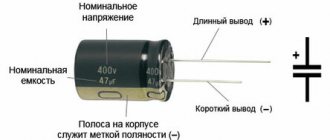
If there are “+” and “-” symbols, determining the polarity will not cause any difficulties; a completely different situation may arise when there are no such indications on the battery case.
At the tablet
For flat tablets, the plus is always located on a larger surface area. Once a positive terminal is detected, the opposite terminal will be negative.
Using a digital voltmeter, you can set the correct polarity; if the red probe is connected to the minus of the battery, and the negative to the plus, then a minus will appear on the display in front of the number that indicates the voltage. This indicates an incorrect connection, that is, the red probe should always be connected to the battery positive.
Using a pointer voltmeter it is even easier to determine the correct connection. If the connection is incorrect, the arrow of the device will deviate to the left, which is unacceptable for such a measuring device.
Note! If you mix up the probes when determining polarity, then nothing bad will happen to the battery or device.
Cylindrical
In round batteries, the plus has a slightly convex plane, so it will be extremely difficult to confuse the positive and negative terminals, even if there are no markings on the product body.
If there are flat contacts on both sides, this parameter can be checked using measuring instruments, and almost any dial indicator can be used for this purpose.
Such elements have an electronic coil, which, when voltage is applied, deflects the arrow in a certain direction. To ensure the accuracy of the experiment, you must first connect a battery with a known contact arrangement to the arrow, and then diagnose the test sample.
Crowns
The crown has a convex positive terminal and a smaller negative terminal; moreover, such a power supply is connected via a special terminal block, in which the contacts also have different diameters. You can also check the polarity using any current measuring device.
How to properly connect a car radio
Tell me how to connect correctly so that plus to plus?
I read this, try it. “Let’s say the speaker is bent outward, then take and mark with varnish (paint, thread, chewing gum) the terminal to which the “+” battery is attached. Do this with all speakers. If the speaker bends inward, then the terminal where the positive battery is attached is negative. „
You can remove the radio and see which output wires the blue and green wires are connected to. Usually the negative wire has a black stripe, the positive wire is clean. So you’ll figure out where the plus and where the minus are. And Caban325 has already said about the location of the plus on the column. I’ll also add that the correct operation of the speaker is when the membrane works to jump out of the housing. If the membrane is pressed into the body, the polarity should be changed.
It's actually not that complicated. Here is a standard car radio connection diagram.
The radio connection cables included in the kit are usually short; they are extended with additional wires. Well, or you can remove the radio and see which connector, find the pinout of the connector. And use it to determine what goes where.
to our channel in Yandex.Zen
Even more useful tips in a convenient format
Replacing the low beam lamp Mitsubishi Lancer 9
There are floor-standing speakers that do not have acoustic terminals.
Judging by the lid, they were bi-wired.
Visible wiring through the terminal cover is made with wire of the same color (Grey).
On the front panel, the speakers are screwed on as if from the inside. No visible bolts.
And all the surfaces around are varnished, I don’t even want to try to pick at them.
The question is, is it possible to somehow, without disassembling the speakers, test or somehow determine the polarity of the speakers plus minus for proper connection to the amplifier.
Answers
that is, there are a pair of wires sticking out from each speaker?
Do you know the brand and model of the speaker system? You can also upload a photo, otherwise from what is described you might think of Elegy))
The polarity of turning on the woofers in the speakers can be easily determined using a regular 1.5V battery. Connect the battery to the speaker wires and look at the woofer itself; when power is supplied to it from the battery, the speaker cone will either move forward or retract back. Remember the polarity of connecting the battery; when the diffuser moves forward, this will be the “correct” polarity for connecting the speakers to the amplifier. Mark the positive wire of the speaker cable on your speakers, for example, with a red felt-tip pen, so that you do not have to carry out the procedure for determining the polarity of connecting the speakers to the amplifier in the future.
they say the wires are routed out for bi-wiring, the tweeter may not survive such a relationship, although the capacitor should be in front of it, of course, but it will be difficult to understand where
I checked the polarity of the speakers in the speakers with a battery many times, so far everything was fine with the tweeters.
I wonder if the downvoters are at least somehow trying to understand the essence of the message, albeit somewhat clumsily written? Topicstarter asked a question like “how to distinguish a pre from a power?”, accordingly, it can easily not distinguish between the terms biamp and biwire, and given the terminals amputated from the speakers, it is quite possible to assume that they were connected with a bimap, having previously amputated the built-in cross-connects. And in this case, there is some probability of burning the tweeter with a good alkaline battery. This is exactly what Bbhob wanted to warn against. Or maybe there is no such probability, I have no desire to check, I don’t have an unnecessary tweeter at hand)))
How to determine the polarity of the speakers?
Master's answer:
Having multiple speaker drivers in your stereo system requires that they be connected in phase. Therefore, despite the fact that alternating voltage is supplied to the speaker, its polarity must be marked on it. It is the polarity value at which the diffuser moves forward that must be marked on the terminals of each acoustic head.
To determine the polarity of your speaker, you need to make a special device, the so-called probe. In a regular flashlight with an incandescent lamp, you need to disconnect the switch and connect two probes instead. The handles of these probes must be insulated to avoid the appearance of self-induction voltage at the head terminals when the voltage is turned off.
After checking the polarity on the probes using a test voltmeter, you need to put symbols on them that correspond to this polarity. When the probes are closed, the flashlight light should light up.
Now you need to completely unplug the amplifier and your entire stereo system. To do this, after turning off the system, you need to unplug the cord from the outlet. Having disconnected the dynamic head output systems from the remaining circuits, it is necessary to connect both probes to the head terminals, without touching the metal parts and the terminals of the probes themselves. Looking carefully at the diffuser, watch how it moves. The cone moving outward when connected and inward when disconnected is evidence that the polarity of the speaker is correct. If the picture is reversed, you will need to change the polarity of connecting the probes and check again.
The polarity corresponding to the polarity of the probes must be marked with an indelible marker on the head frame.
In the same way, you need to check all the speakers of your speaker system. It does not matter how they are connected, directly or through a crossover. The positive terminals of the heads must correspond to the red contacts on the rear wall of the speaker, that is, the connection must be made in-phase.
Perhaps the second speaker system needs to be checked and rebuilt. Closing the two speaker cabinets will help determine if they are connected to the amplifier correctly. The cable with which they are connected to the amplifier should have red marks. A conductor that has a red mark on it should only be connected to a terminal of the same color. The conductor without a mark must be connected to the black terminal.
The sound of your stereo system after all these manipulations will significantly change for the better. You will see this for yourself when you turn it on.
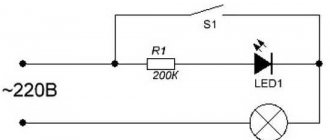
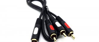
Schemes for connecting speakers to the radio
p, blockquote 6,0,0,0,0 —>
Currently, most car radios use a standard ISO interface for connecting external speakers and speakers. Its functional diagram and pinout of pins on the connector are shown in the figure.
p, blockquote 7,0,0,0,0 —>
p, blockquote 8,0,0,0,0 —>
The diagram shows that connector B is responsible for connecting speakers and speakers, from which wires of different colors extend. The primary color wire is connected to the positive terminal of the speaker, the two-color wire is connected to the negative terminal. In many radios, the signal is transmitted through a single-color wire, the two-color wire is common (ground).
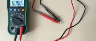
Determining polarity with a multimeter
Sometimes it happens that a new electrical device that needs to be connected does not have polarity markings, or it is necessary to re-solder the wiring of a damaged device, and all the wires are the same color. In such a situation, it is important to correctly identify the poles of the wires or contacts. But if you have the necessary instruments, a logical question arises: how to determine the plus and minus of an electrical appliance with a multimeter?
To determine the polarity, the multimeter must be turned on in the mode for measuring direct voltage up to 20 V. The wire of the black probe is connected to the socket marked COM (it corresponds to the negative pole), and the red one is connected to the socket with the VΩmA marker (it is, accordingly, a plus).
After this, the probes are connected to the wires or contacts and the device, the polarity of which needs to be determined, turns on. If the multimeter display shows a value without additional signs, then the poles are determined correctly, the contact to which the red probe is connected is positive, and the contact to which the black probe is connected will correspond to the minus. If the multimeter shows a voltage value with a minus sign, this will mean that the probes are connected to the device incorrectly and the red probe will be a minus, and the black probe will be a plus.
If the multimeter used to measure is analog (with an arrow and a display with gradations of values), if the poles are connected correctly, the arrow will show the actual voltage value, but if the poles are reversed, then the arrow will deviate in the opposite direction relative to zero, that is, it shows a negative current value.
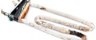
Checking the speaker with a multimeter
To check the contacts, it is necessary to measure the resistance by setting the multimeter to the mode for determining this characteristic.
The probes must be connected to the contacts, observing the polarity of the speaker, and with the diffuser stationary, move them. If the readings on the multimeter display are constantly changing, this will mean that the wiring is damaged and needs to be replaced.
If you turn the speaker over and twist it, you hear extraneous sounds (for example, tapping), then, most likely, several turns or the entire winding have fallen off the sleeve in which the coil is located. This can be corrected by rewinding the winding.
It is also important to carefully examine the voice coil, which is located inside the speaker and looks like a wire wound in a spiral. This coil must have an even, neat winding, without interlacing and random overlaps, kinks, breaks and other mechanical damage.
If mechanical defects are still found, the coil should be replaced. You can carefully rewind an incorrect winding (uneven or overlapping) yourself.
To check the correct rewinding of the reel, it is enough to listen to two or three well-known songs several times. While listening, you need to focus on volume (both minimum and maximum), sound quality (absence of extraneous noise) and sound transitions.
Rotating the diffuser will also help detect defects. If you hear a grinding, crackling or rustling sound when performing this action, then most likely there are foreign objects near the magnetic gap, for example, scrap metal that accidentally fell during assembly and other debris. This can be fixed simply by cleaning the speaker.
If the diffuser turns with difficulty or does not rotate at all, then the problem lies in the displaced coil or sleeve, as well as the displacement of the core, which in turn leads to jamming of the sleeve. This problem can be corrected by disassembling the speaker and installing these parts in the correct position.
The electronics of the speakers can be checked with a tester, ohmmeter or any other device for measuring electrical resistance.
To do this, you need to turn the multimeter into resistance measurement mode and measure this characteristic of the speaker. For polyphonic speakers the average resistance is 8 ohms, and for auditory speakers it is about 30 ohms.
If the measuring device does not show any data, it means that the speaker wiring is damaged, and if it is intact, then the problem is a broken coil. Damaged wiring or a broken coil must be replaced with new ones.
To check the integrity of the coil itself, you need to ring it using a multimeter. In this mode, the tester probes are connected to the speaker contacts.
If the multimeter display shows a value greater than 0, then the voice coil is intact, and if this value is 1, then there is a break in the coil and in this case it must be replaced.
After checking the electronics, it is worth checking the build quality of the diffuser and corrugation. To do this, the speaker must reproduce infra-low frequencies. This will allow you to detect poor-quality gluing of the corrugation and diffuser.
The last thing you should do is check the quality of the speaker using a frequency generator. This speaker test should be performed in the range from 20 Hz to 20 kHz. The absence of wheezing and distortion will mean that the speaker is working properly and efficiently.
These methods will help solve a problem such as checking the speaker with a multimeter.
Source
Selection of connecting wires
p, blockquote 26,0,0,0,0 —>
Installing audio leads is different from normal electrical connections. The fact is that an alternating sound signal propagates through the conductors going to the speakers and speakers. It has a frequency ranging from 20 Hertz to 20 kilohertz. In principle, the frequency is low, but linear distortions, electromagnetic interference, and interference are possible. They degrade the sound quality. Therefore, along with observing the rules for choosing the cross-sectional area of the wire, the type of conductor is selected.
p, blockquote 27,0,0,0,0 —>
The cross-section is usually chosen from the following consideration: for every 10 watts of amplifier power - approximately 1 sq. mm of wire cross-sectional area. That is, with a radio power of 40 watts per channel, the cross-section of the conductor leading to the speaker must be at least 4 sq. mm.
p, blockquote 28,1,0,0,0 —>
You should think about choosing the type of speaker cable if the radio is capable of providing high-quality sound. On the Hi-end equipment market you can find many different speaker cables with unique parameters and prices.
p, blockquote 29,0,0,0,0 —>
p, blockquote 30,0,0,0,0 —>
The feasibility of installing such expensive conductors for a middle-class car radio is zero. The main thing when connecting is to ensure that the phases of the speakers and speakers are synchronized. Otherwise, the interior will be filled with cacophony instead of high-quality sound.
p, blockquote 31,0,0,0,0 —>
How to properly connect speakers to a car radio
From the point of view of acoustic properties, the car does not have the best characteristics. The interior has a complex architecture; it contains structures made of various materials: metal, upholstery, plastic, rubber, etc. It is rare that a manufacturer specifically optimizes the interior to ensure high-quality sound.
However, standard speaker installation locations are selected to ensure the greatest sound propagation efficiency. Usually they are located in the doors, on the front panel, under the rear window. If you decide to install more powerful speakers, you will need to remove the old system, measure their mounting dimensions (diameter in inches and depth) and purchase speakers of the same size but with better characteristics.
It is also necessary to choose speakers (speakers) with exactly the same internal resistance. The standard resistance value is 4 Ohms. There are high-power radios that allow a load of 2 ohms. If you connect them to 4 ohm speakers, you will lose power. If you are connecting a new car radio, you should use reference books or technical descriptions to accurately determine the power and load resistance. If the speakers have less resistance than the radio allows, the latter may fail; if it has more resistance, it will not be possible to “swing the system to its full potential.”
You cannot connect additional speakers or speakers in parallel. In this case, the load resistance decreases. At best, the speakers will wheeze, at worst, the radio amplifier will burn out.
Many car enthusiasts install additional speakers in the trunk. In this case, they must be firmly secured. Firstly, it will improve the acoustic parameters. Secondly, it will protect the speakers from premature failure.
Some radios have a complex system for connecting speakers, speakers and subwoofers. It may include isolation filters, amplitude coupling devices for outputs and inputs, and additional amplifiers. In this case, you need to find an original diagram for connecting the speakers to the radio, similar to this one.
If you decide to install a system of this level, but do not have the appropriate skills, it is better to use the services of a specialist. At the same time, you should think about additional noise and sound insulation of your car.
Recommendations for connecting a car radio
How to properly connect a car radio? Almost every car enthusiast has asked this question at least once? In this article we will tell you how to do it yourself, without turning to specialists. The car radio is powered by a battery. This is where danger awaits the inexperienced installer: out of ignorance, you can turn the plus to minus of the car radio or speakers.
Some car enthusiasts power the radio from the ignition switch or cigarette lighter - this is easier, but will affect the sound quality. The wire with which we lead the plus must be copper and stranded, about 4 mm2. in diameter. And in length it should be as short as possible.
We install an additional fuse at a distance of approximately 40 cm from the positive terminal of the battery, take the nominal value 10 - 20 A. The negative wire should be as long as possible.
These wires need to be laid at a distance from each other; we connect them to the car radio after connecting the speakers. Be careful not to let the positive wire touch the radio body or any of the speaker wires.
Now let's start explaining the correct phasing and connecting the speakers. Each of them has positive and negative terminals.
The narrow terminal is most often negative, and the wide terminal is positive. The wires from the radio are marked: those that are plain are the plus of the channel, and those with a black stripe are the minus of the channel. So, we connect the one with a single color to the wide terminal, and the one with a stripe - to the narrow one.
How to determine plus and minus using a multimeter
Accurate knowledge of the polarity of an electrical appliance is extremely important. After all, if you connect electrical equipment with incorrect polarity, it may either not work or be completely damaged. In most cases, the “plus” and “minus” of wires and contacts in such devices are indicated by letters, symbols or colors (on the case near the contacts there is a “+” and “-” marker, and the wires are black for minus and red for plus) .
But sometimes it happens that it is not possible to visually determine the poles. To do this, you can use either an ordinary polarity tester or improvised means.
Determination of polarity by alternative methods
If it happens that you don’t have a multimeter at hand, but you need to find the polarity, you can use alternative and “folk” means.
For example, speaker wiring charges are checked using a 3-volt battery. To do this, you need to briefly touch the wires connected to the battery to the speaker terminals.
If the cone in the speaker begins to move outward, this will mean that the positive terminal of the speaker is connected to the positive terminal of the battery, and the negative terminal to the negative terminal. If the diffuser moves inward, the polarity is reversed: the positive terminal is connected to the minus, and the negative terminal to the plus.
If you need to connect a DC power supply or battery, but there are no polarity markings on them, and you don’t have a multimeter at hand, plus and minus can be determined by “folk” methods using improvised materials.
The easiest way to determine polarity that you can use at home is to use potatoes. To do this, you need to take one raw potato tuber and cut it in half. After this, two wires (preferably of different colors or with any other distinctive sign) with their bare ends are stuck into a cut of potato at a distance of 1-2 centimeters from each other.
The other ends of the wires are connected to the constant current source being tested, and the device is turned on (if it is a battery, then after connecting the wires, nothing else needs to be done) for 15-20 minutes. After this time, a light green spot will form on the potato cut around one of the wires, which will be a sign of a positive charge on the wire.
The second method also does not require any special devices or tools. To determine the polarity of the wires of a DC source, you will need a container of warm water into which two wires connected to the power source are lowered.
After connecting the device to the network, gas bubbles (hydrogen) will begin to appear around one of the wires - this is the process of electrolysis of water. These bubbles form around a source of negative charge.
The following method is suitable if you have an unused, working computer cooler. The method for determining polarity using this method is that the cooler must be powered from the uninterruptible power supply being tested. But often there are three wires in coolers:
- black, responsible for negative charge;
- red, responsible for positive charge;
- yellow is the speed sensor.
In this case, the yellow wire is ignored and is not connected anywhere. If, after connecting the cooler to a constant voltage source, the cooler starts to work, then the polarity is determined correctly, the plus is connected to the red wire, and the minus is connected to the black. And if the cooler does not work, this will mean that the polarity is incorrect.
How to determine speaker polarity using a battery
It is more difficult with the phasing of BRIDGE amplifiers. They do not have a single output wire attached to the body. In such cases, if the amplifier has a button for turning on the “MONO” mode, you can, by switching the amplifier to this mode, applying an input signal to it and connecting the speaker to one wire of one channel, send a signal to the other end of the speaker alternately from both wires of the other channel. When the same wires of both channels are connected to the speaker, there will be no sound in it (due to the variation in the characteristics of the channels, the sound may be greatly weakened). If there is no “MONO” mode, you can stupidly connect the amplifier inputs (LC and PC) together and feed them a signal from one channel of the signal source. The notes on the polarity of connecting speakers are the same: the polarity is not important, it is important that the same poles of the speakers are connected to the same poles of the output.
There are floor-standing speakers that do not have acoustic terminals.
Judging by the lid, they were bi-wired.
Visible wiring through the terminal cover is made with wire of the same color (Grey).
On the front panel, the speakers are screwed on as if from the inside. No visible bolts.
And all the surfaces around are varnished, I don’t even want to try to pick at them.
The question is, is it possible to somehow, without disassembling the speakers, test or somehow determine the polarity of the speakers plus minus for proper connection to the amplifier.
Answers
that is, there are a pair of wires sticking out from each speaker?
Do you know the brand and model of the speaker system? You can also upload a photo, otherwise from what is described you might think of Elegy))
The polarity of turning on the woofers in the speakers can be easily determined using a regular 1.5V battery. Connect the battery to the speaker wires and look at the woofer itself; when power is supplied to it from the battery, the speaker cone will either move forward or retract back. Remember the polarity of connecting the battery; when the diffuser moves forward, this will be the “correct” polarity for connecting the speakers to the amplifier. Mark the positive wire of the speaker cable on your speakers, for example, with a red felt-tip pen, so that you do not have to carry out the procedure for determining the polarity of connecting the speakers to the amplifier in the future.
How to determine plus on a radio
Often people come and say - well, I installed the radio in the car myself, but the sound is kind of crap. You can see? Let's see. If we separate the radios that cost 1000 rubles, from which there is no point in asking for good sound, then the rest are either not configured with really basic settings like an equalizer, or the polarity of the speaker is reversed.
The fact is that by connecting all the speakers correctly, with the same polarity, they all play in the interior and the sound is good. And if you connect the polarity differently, then some will play in the door, others in the interior. This is a very primitive explanation, but I think it’s understandable. When you connect speakers with different polarities, the sound becomes “flat” and not bassy or rich, no matter how much you turn up the equalizer.
The same problem occurs when buying a car second-hand, where instead of a radio there is a hole, instead of a radio connector there is a cut off bundle of wires.
I've filmed the simplest way to determine which wires in a bundle are speakers, and how to determine the correct speaker polarity.
The polarity of the speakers in the car. How to connect correctly?
Often, if we consider radios in the range of up to $40-50, especially Chinese brands, then you shouldn’t expect good sound.
In other cases, I installed the radio and didn’t even bother with the equalizer settings. But most often it is the polarity of the speaker that is reversed.
When connecting speakers, this feature should be taken into account. It is necessary that the diffusers of each speaker oscillate synchronously.
If the speakers do not work synchronously, then the sound picture may be distorted, since the sound waves will be in antiphase - partially compensating each other. In this case, the spatial orientation of the sound source may be distorted, etc.
And if the speaker diffusers operate in phase, the sound vibrations will add up, thereby creating a complete and accurate sound picture.
We have created for you the simplest way to determine the polarity of the speaker.
No duplicates found
Automotive community
11.9K post 33K subscribers
Community Rules
Welcome to the automotive community!
-Publication of videos on the subject of road accidents (exception: original content with description).
-Break the rules of the site.
-Create posts that do not correspond to the topic of the community.
-Advertise anything.
-Accordions are not advisable (ignoring the accordion meter is punishable by flugegeheimen).
-Brew chamomile tea in a giraffe costume.
-Create interesting content.
-Participate in the life of the community.
-Suggest topics for posts.
-Call the administrator or community moderators if necessary.
-Express ideas to improve the Automotive Community.
-Image a horse when commenting.
Check the tweeters and upper midrange by ear. Sometimes they play better out of phase, and I've done this quite often with the HF to improve the scene.
On the wiring 1) We are looking for a diagram on the car 2) Or we are looking for thick twisted pairs, usually there are 2 or 4 of them (if there are 4 speakers) pair = speaker 3) If the car is simple (more precisely, you do not have a channel bus on the radio (thin twisted pair), we call control plus, minus, dimensions, speedometer, etc., and put them aside. And those that did not ring, we ring by tapping the battery
Yes, this is the case on Mondeo 4. From the GU, 2 black wires come to the door to the speaker, inside the speaker they are distributed, and 2 more wires from the speaker go to the tweeter (tweeter)
I turned off the GU, and instead of the speaker, I connected the battery and you look in which direction the speaker diffuser is moving.
Or did I not understand your problem?
If the speakers do not work synchronously, then the sound picture may be distorted, since the sound waves will be in antiphase
I probably don’t understand something, but does the interference of two counterpropagating waves depend only on their phases? Doesn't the distance between sound sources and the listener's ears matter?
If it is not very clear, again. Two waves from two sound sources meet, one in phase, the other in antiphase, and cancel each other at the point where their phase and antiphase coincide, and at the point where the phases coincide, they are amplified. It is worth moving the place where they meet by half the wavelength (move your head), and where the phase met the antiphase there will be the opposite picture.
General concepts about the device
Car receivers are divided into two types depending on the method of their installation:
- Stationary - suitable for certain car brands due to their original shape and non-standard size. Such models are built into the car at the assembly stage. For example, such a model is the standard radio on the Chevrolet Cruze DWGM1001 or the Subaru Clarion model installed on the Subaru Impreza.
- Built-in - universal receivers, most have a removable front panel to protect against theft. An example of such models are Pioneer players.
The connectors of the device also play an important role. There are many types of connectors, the most preferred is the ISO standard. If the connectors do not match, you must purchase a corresponding adapter.
Connection diagram
The essence of the operation of a car radio and its switching is in the following sequence:
- The negative of the battery is connected directly to the receiver.
- The voltage from the battery positive cable is sent to the fuse, and then the power goes to the branch: permanently connected + 12V power, as well as to the ignition key
- Through the positive cable of the ignition switch, current flows to the control terminal
Installation of the device is carried out by connecting the appropriate wires, and this requires an understanding of the polarity of the receiver.
Basic Wire Pinout
In order to find the plus and minus on the radio, you need to know the pinout of its wires.
Wire location
Most manufacturers develop devices using a standard wire color scheme, knowing which it is easy to determine its pinout:
- Red – designated ACC. This is a plus of the ignition switch, which appears when it is turned, that is, when the car starts.
- Yellow – designated BAT and does not depend on the ignition switch. This is a plus for the battery.
- Orange – designated ILL. This is a plus that connects to the terminal to switch the lighting.
- Black – marked GND. This is a permanent minus of the battery.
- White with stripes FL- (minus) and without stripes FL+ (plus) - front left speaker wires.
- Green without stripes, marked RL+ (plus) and with stripes RL- (minus) – rear left speaker cable.
- Gray with a stripe is marked FR (minus) and without stripes FR+ (plus) - the wires of the front right speaker.
- Purple without a stripe RR+ (plus) and with a stripe is marked RR- (minus) - the rear right speaker.
Knowing the basic color code of the cables, you can easily determine which wires on the radio are plus and minus.