Connecting an electric stove: instructions for installing and connecting the stove yourself
Free-standing electric stoves, despite the popularity of built-in kitchen appliances, still remain in demand.
They are cheaper, but at the same time they are not inferior to integrated units in terms of technical characteristics and design. And installation takes little time and does not require special preparation. Correct installation and compliance with operating requirements are the conditions for long-term service, so homeowners often call a technician from a service organization or simply an electrician they know. But you can save a lot of money by doing everything yourself. Do you agree?
But what is needed for this and how to do it correctly? We will help you figure out the task - in our article we will describe in detail how to connect an electric stove on your own. We will also analyze the nuances of choosing wiring and protective equipment, consider grounding methods and connection diagrams. This information may be useful to you not only when installing the stove, but also in the future, during repairs or replacement of equipment.
Connecting electric stoves hansa, electrolux, bosch, zanussi and others
Electric stoves have long been part of our everyday life, but, unfortunately, not everyone knows how to connect them. So, if you have purchased one of these stoves and are planning to connect it yourself, this article will help you with this. In it, we will try to explain step by step how to do this competently, and most importantly, safely!
It is also worth noting that although electric stoves are considered household, they consume quite a lot of power - this should be taken into account both during installation and during further operation of heating electrical appliances in everyday life.
Before installation, carefully read the contents of the installation instructions. If any points cause you doubt, then it is better to entrust the installation to a qualified electrician. Remember that the manufacturer's warranty does not apply if the electric stove is connected in violation of the rules and regulations for the installation of electrical equipment.
We suggest considering how to choose the right components for installation: cable, plug, socket, circuit breaker. Connect the electric stove and oven to a single-phase, two-phase, three-phase power supply network of 220 and 380 Volts with your own hands.
Electric stove connection diagrams
First, let's look at the general rules. An electric stove is a powerful household equipment that consumes 40-50 A of current, so a separate electrical circuit is allocated for it. It connects two points: the circuit breaker in the apartment/house electrical panel and the socket/terminal block of the device.
In practice, 3 types of network connections are used:
If the kitchen already has a pre-installed power outlet powered by a separate circuit breaker, they usually use it. This is more familiar, and if repairs are necessary, the device can be quickly turned off without leaving the kitchen.
But often a direct terminal connection is used. It is considered safer and more reliable. The disadvantage of a non-socket connection is that you will have to disconnect the stove from the network each time at the electrical panel.
The connection diagram depends on the number of phases involved. Domestic equipment is designed for 1- or 3-phase connection, but we propose to analyze all three possible options, including 2-phase.
To connect the terminals of the plate with the conductors, jumpers made of copper wire are used. Modern equipment is usually equipped with the necessary parts for connection.
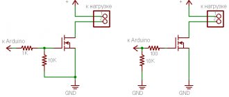
In the single-phase method, the phase is connected to terminals 1, 2 or 3, all of them are connected to each other by jumpers. Zero goes to 4 or 5, which are also connected, and ground goes to terminal 6.
From the diagram it is easy to understand how other types of connections are made. There will be no problems finding the diagrams - they can be found in the technical documentation for the electric stove or on a plate attached near the terminal block on the back wall.
Connection to a two-phase network
A rare, but still common connection method.
The connection diagram for an electric stove operating from a two-phase network is somewhat different, since this requires a cable with 4 cores, two of which will be phases, the other two will be zero and ground.
The connection is made as follows: connect the ground wire, then use a jumper for the zero terminals and connect the neutral wire.
If the plate has three phase terminals, then connect two of them with a jumper and connect one phase wire to one of the terminals, and the second phase wire to the remaining third terminal.
Requirements for circuit breaker and wiring
Before proceeding with the connection, you should find out whether the wiring corresponds to the potential load and whether a separate circuit breaker is installed in the electrical panel. If there are no elements for installation or they do not match the nominal value, we recommend purchasing them in advance along with the stove.
Powerful electrical appliances are not only allocated a separate line, but also have individual double protection: ideally, this is a set of RCD + circuit breaker.
Instead of this pair, to save space in the shield, a difavtomat is often used.
When purchasing a machine, the decisive criterion is the rating, which is chosen based on the maximum value of current consumed. Usually this is 40-50 A, but it is better to clarify the technical data in the stove’s passport. We recommend that you familiarize yourself with the rules for choosing a machine in more detail.
To guarantee safety, the nominal value is selected upwards - this way, when operating at maximum loads, the protection will not be constantly triggered. Let's assume that the maximum current consumption is about 45 A, therefore, a 50 A circuit breaker is needed.
To select an RCD, the principle is the same - upward, that is, paired with a 50 A machine, they put a 63 A RCD.
There are no particular difficulties with the choice of wires either. Aluminum cable is not suitable - it is better not to use it at all for home electrical wiring. This is unsafe, and its characteristics are inferior to its copper counterpart. Therefore, we settle on a copper wire with a cross-section corresponding to the power and current consumption.
If during the preparatory work you still have to buy wires, you need to focus on the power parameters of the stove:
For a three-phase network, a 5-core wire of 2.5 mm² is used.
If you have not yet decided which model of stove you will buy, but have already started replacing the wiring, you can safely buy VVGng 4 mm² wire - if the distance from the stove to the panel is no more than 12 m, and VVGng 6 mm² - if the electrical panel is further away. Modern stoves and ovens are quite powerful, so you can’t go wrong.
Now let’s figure out in what order it is better to perform all the actions.
Connection to a three-phase network
To connect a stove operating from a three-phase network, you need a cable with 5 cores, 3 of which will be phases, the other two - ground and zero.
Again, first connect the ground and zero, having previously shorted the zero terminals with a jumper, if there are several of them.
We connect one phase wire to the three phase terminals.
The colors of the phase wires may be different, but it is important to remember that the neutral wire is always blue or light blue, and the ground wire is yellow-green.
Keeping this in mind, you can easily connect the cable to the stove, and it does not matter what network it is on.
Conclusions and useful video on the topic
Detailed instructions with explanations + soldering of wires:
How to correctly connect a plug to a wire - clearly and comprehensively:
As you can see, connecting an electric stove has its own difficulties, but if you know the necessary information, you can do it yourself. Of course, the main help is technical documentation - connection diagrams and manufacturer’s recommendations for choosing devices.
Now you have knowledge that can be useful when repairing or replacing equipment. Do not forget that to connect, you must check the wiring characteristics and install automatic protection .
If you know interesting and useful nuances of installing an electric stove, join the discussion below in the comments. Write down what difficulties you encountered when connecting your model, and what mistakes you managed to avoid.
Source
Connection without socket
Connecting a stove without using an outlet, but using a terminal block, is practically no different.
The wire is connected to the machine, the RCD is cut in, and the wire is pulled to the installation site of the stove.
A recess is made in the wall into which a protective box is installed. The terminal block is placed in this box.
The wire coming from the distribution panel, as well as the cable from the stove, is supplied and connected to it.
They are fixed in the terminal block; it is important not to confuse which wire is which.
After this, the protective box is closed with a lid. Well, then – a performance check.
It is noteworthy that the connection diagram for electric stoves is almost the same.
Many people are familiar with Hansa and Mechta electric stoves. Buyers often ask how to connect them correctly.
Since there are many models of stoves, it is difficult to guess which one you purchased. But we described all possible connection methods above.
See the power consumption and what wiring your model is designed for (single-phase, two-phase or three-phase) and apply our recommendations.
The Hansa stove from a foreign manufacturer is connected to the network, just like the domestic Mechta stove. It is only important to choose the right wiring and all other elements included in the power line.
Popular among readers: Methods for replacing electrics in an apartment.
Independent connection of an electric stove to a 220 V, 380 V network
Electricity is a serious and dangerous matter, but many jobs do not require high qualifications and can be done independently without the involvement of specialists. For example, you can connect an electric stove with only a vague understanding of electricity. Especially if the outlet is already installed. All that remains is to install a plug on the cord and connect it correctly to the connectors of the stove. The situation is worse if it is necessary to pull the line from the shield, but even here you can cope without help. Just remember that all work is carried out with the power supply turned off.
Scheme
Regardless of the connection method via a socket or terminal block, the stove or hob can be connected to the network according to three schemes:
For 220V devices, a single-phase circuit is used; for 380V, two or three-phase options are used. Before connecting an electric stove or hob, you will have to turn it around with its back side and remove the protective cover from the terminal box. Possible connection diagrams are usually indicated on the back of the device.
Single phase
This is the most common option in a high-rise apartment. It can be used when the connection is made with a three-wire wire. It is easy to do with your own hands. To properly connect the device, you must use jumpers. They usually come complete and are bolted into the terminal box. If they are not available, you can purchase copper jumpers with a cross-section of 6 mm. Five of the six screws are connected by two busbars:
- one bus connects the screws marked with the letter “L” under numbers 1, 2, 3;
- the second is used to connect numbers 4 and 5, indicated by the letter “N”;
- the latter remains free and will be used for grounding.
When connecting, the wires are distributed as follows:
- phase (black or brown) on L1,2 or 3;
- zero (blue) on N4 or 5;
- The sixth terminal with the designation PE is used for grounding.
Two phases
This scheme is most often used for a private house, but it can also be used in an apartment. The connection is made with a four-core wire. In this case:
- one jumper is placed on L1 and L2;
- another on N4 and N5;
- L3 and the ground screw remain free.
To connect such a circuit:
- the yellow wire is placed on phase A consisting of terminals L1 and L2 connected by a jumper;
- the core in the red winding goes to the nearby terminal L3;
- blue color is placed on zero N4 and N5, connected by a jumper;
- yellow-green is intended for grounding.
Three phases
This option is intended for a private house; in an apartment this scheme is rarely used. Despite the external complexity, it is just as easy to implement with your own hands. It is performed with a cable of four or five cores. Here, only one bus is used to connect the adjacent zero terminals N1 and N2. The wires must be connected in the following order:
- to phase A, contact L1 goes yellow;
- to phase B, contact L2 – green;
- to phase C, contact L3 – red;
- blue is intended for adjacent zero terminals;
- for grounding light green or yellow-green.
When doing all of the above work with your own hands, you need to spend time consulting with specialists. This will protect you from irreparable mistakes and allow you to do everything right.
Connection diagram and methods
Electric household stoves are powerful equipment; the current they consume is about 40-50 A. This means that the electric stove must be connected to a dedicated power line. It must be powered directly from the apartment or house panel. Power is supplied through an RCD and a circuit breaker. The stove itself can be connected via a socket and plug (special power ones) and a terminal box. Also, the line from the machine can be directly connected to the input terminals on the rear wall.
Electric stove connection diagram
A more reliable connection is directly to the input terminals of the plate. In this case, there is a minimum number of contact points, which increases reliability. But this method is not entirely convenient: you can only turn off the power automatically. About the same problem occurs when using a terminal box, the only difference being that there are more connection points.
The most commonly used connection is a socket and plug. It's more convenient and familiar. Since the equipment is powerful, they use not ordinary household devices, but special ones, which are also called power devices - for their ability to withstand significant current loads.
Please note that when connecting powerful electrical equipment, grounding is required. Without it, you will be denied warranty repairs, and its absence is life-threatening, so it’s better not to take risks.
Self-connection of an electric stove
Step-by-step instructions for connecting electric stoves electrolux ekc (electrolux), zanussi (zanussi), hansa (hansa), gorenje (burning), bosch (bosch), ariston (ariston), beko (eyelid), hotpoint, indesit (indesit), greta, kaiser (kaiser), aeg, nord ep, samsung to power supply:
Step 1 - Power Cables, Circuit Breaker and RCD
The power supply to the electric stove must be carried out by an independent cable going directly to the apartment's distribution board. To lay the cable from the switchboard to the socket, you can use cable brands: VVG; VVG-ng; PVS; SHVVP. And from the outlet to the stove, it is better to connect with multi-core wires, for example PVA or KG, which are more resistant to breaking when repeatedly bent during operation.
The cable cross-section depends on the network voltage, the number of phases and power consumption. Knowing these parameters, you can select the appropriate cable from the table. It is better to take the conductor cross-section with a margin of one order of magnitude larger.
Table: selection of cable cross-section
The connection must be made from a separate circuit breaker. The rated current of the machine must be one rating higher than the current consumption of the electric stove.
All characteristics of the electric stove can be found in the technical documentation that is included with the purchase, and they are also indicated on the body. The time-current characteristic of the circuit breaker must be group C.
It is also advisable to install a residual current device (RCD), which will protect a person from electric shock if he accidentally touches faulty equipment. The RCD is installed next to the circuit breaker and connected after it. Its denomination should be an order of magnitude less than the machine. Ground leakage current is no more than 30 mA. All screw terminals must be tightly clamped, as large current will pass through them.
Step 2 - Installing the Outlet
Not every apartment has a power outlet in the kitchen, designed to connect powerful equipment that consumes more than 3 kW. This is usually a single-phase power outlet that is rated at 32A or 40A.
We suggest you consider how to choose and install the right socket for an electric stove:
Turn on the circuit breaker in the apartment's distribution panel. Use a multimeter to check the presence of voltage at the phase contacts of the socket.
Step 3 - Open the back panel of the cooker
To connect the cable to the electric stove, on the back side you need to find and unscrew the small cover that covers the terminals for the wires.
Rear wall of a domestic stove
Step 4 - Securing the Cable
After you have removed the cover, you need to secure the cable. This is done in order to avoid accidentally pulling the cable out of the plate. Insert the cable and secure it to the stove body in a special clamp.
Electrical parameters and ratings of circuit breakers
As we found out, there should be separate RCDs and a circuit breaker in the electrical panel. Through them the phase is supplied to the socket. This pair can be replaced with a difavtomat. These are the same two devices, but in one case. The negative is taken from the common bus, passes through the RCD, and the grounding is taken from the corresponding bus.
The rating of the machine is selected based on the maximum current consumption. This data is in the electric stove's passport and is usually in the range of 40-50 A. In this range, the ratings come in large increments - 40 A, 50 A, 63 A. It is better to choose the nearest larger one - this way there is less chance of a false shutdown when operating at full power . That is, if the declared maximum current consumption is 42-43 A, still take a 50 A machine.
Electric stove connection diagram
On the other hand, you may never turn on all the burners and oven, and even at full power, and more powerful machines are significantly more expensive. It's up to you to choose.
The rating of the RCD is taken one step higher than that of the machine.
If you decide to install a 50 A machine, then the RCD is required at 63 A, the leakage current is 30 mA.
Residual current device and circuit breaker
An RCD and a circuit breaker are a mandatory element of the kit, which is used to independently connect any household appliance to the network. Their presence will protect the device from power surges and premature failure:
- They are placed side by side on the mounting rail up to the meter.
- The nominal value of the RCD must be greater than the machine.
- The RCD is connected to the meter by the upper phase and zero mounts, respectively.
- The lower terminals are used to connect to the machine and are brought to zero.
- If a single-pole circuit breaker is used, the zero terminal of the RCD is connected to the zero bus.
- With a two-pole connection, the zero terminal is connected to the corresponding contact of the machine.
- The phase and neutral conductors of a three-core wire are placed on the lower mounts of the machine.
- If the machine has a single-pole neutral wire, it goes to the corresponding bus.
- Yellow-green or green is intended for grounding.
Wire and its parameters
In recent years, when laying electrical wiring and connecting household appliances, copper conductors are most often used. Although they cost much more, they are more convenient to work with, and besides, copper requires a much smaller core diameter than when using aluminum conductors.
The conductor cross-section is selected depending on the type of network - 220 V or 380 V, the type of wiring (open/closed) as well as the current consumption or power of the equipment. Typically, copper conductors with a core of 4 mm (for line lengths up to 12 m) or 6 mm are used.
General requirements
It is impossible to correctly connect an electric stove or hob with your own hands without meeting certain equipment requirements. In an apartment this can be done much easier and faster.
Typically, in a standard high-rise apartment, such devices are connected to the network with an already installed separate wire, through a specially designed socket. This will save time and allow you to quickly connect the stove or hob.
Owners of a private house will have to carry out all the work related to the wire and install other equipment themselves or with the invitation of a specialist. In this case, you should use:
- three-core copper cable with a cross-section from 4 to 6 mm depending on its length;
- a separate automatic switch for an electric stove for installation in a panel at 32 or 40A in accordance with the wire cross-section;
- residual current device;
- accessible method of grounding.
How to connect an electric stove to a 220 V network
All the above diagrams were specifically for a single-phase 220 V network. To connect, you will need a three-wire cable, a three-pin power socket and a plug with a rated current of at least 32 A. Let’s say right away that connecting equipment from different brands is fundamentally no different. It doesn’t matter which stove you purchased - Electrolux, Gorenje, Bosh, Beko. Doesn't matter. The only difference is the different design of the covers that cover the terminal box on the housing and different methods of fastening it. Everything else is the same.
Connecting the cable to the electric stove
First, the cable selected for connection must be connected to the electric stove. On the rear panel, usually at the bottom left there is a terminal block to which the conductors are routed.
The terminal block to which the electrical cord must be connected
Nearby are connection diagrams for different networks.
Schematic illustration of connections for different networks
With a 220 V network, the diagram is on the far right. On the plate, contacts 1,2,3 should be connected by one jumper - this will be the phase (red or brown conductors), the second - contacts 4 and 5 - this is neutral or zero (blue or blue), the sixth contact is ground (green or yellow -green). Electrical plates usually come from the store with jumpers already installed, but it doesn’t hurt to check.
Connecting the cable to the electric stove
It is more correct and reliable to crimp the conductors with contact plates, and then connect them. This connection is more reliable, but often the conductors are simply twisted around the clamping screw and then tightened. In any case, it is better to follow the color coding - this way there is less chance of making a mistake.
It is better to terminate the conductors with contact plates
Plug installation
Next, a plug is connected to the cable. The power plug is collapsible. Unscrew the two mounting screws and remove the cover with contacts. The fixing bar holding the cable is also removed. The protective insulation is removed from the edge of the flexible cable (about 5-6 cm), the conductors are straightened, their ends are also stripped of insulation by about 1.5-2 cm. The cut end of the cable is inserted into the plug body.
This is what the plug for connecting an electric stove looks like
The clamping screws on the contacts are loosened, the conductors, if they are multi-core, are twisted into a bundle. These flagella are twisted around the contacts and tightened with clamping screws.
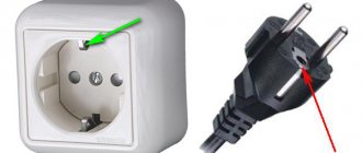
The distribution of conductors matters and they must be connected carefully. The top contact of the plug is usually labeled - the “ground” wire (green) is connected here. When connecting a socket, you need to apply ground to a similar connector.
Connecting the wire to the electric stove
The other two contacts are “phase” and “zero”. Where to apply which one is not important, but when connecting the socket, the “phase” must fall on the “phase”, the “zero” must fall on the “zero”. Otherwise there will be a short circuit. So before turning it on, be sure to double-check that the wires (phase and neutral) are screwed in correctly.
How to determine the phase in an installed socket
If you already had an electric stove before, and there is a socket, you need to find in it where the grounding, phase and neutral are located and connect the wires in the plug accordingly. The easiest way to determine this is to use a voltage indicator in the form of a screwdriver. It works simply - install the indicator in the place of the expected phase, and look at the LED mounted in the housing. If it lights up, then there is voltage and this is a phase. If there is no voltage, the LED does not light up, and this is zero.
The ground is even easier to determine: is the contact at the top or bottom.
Connection to a single-phase network
In the electric stove, under the protective cover, there are contacts to which the wire is connected.
For a single-phase network, this cable must be three-core.
One core is phase, the second is zero, the third is grounding. In the cable, each core has its own color. It is important to remember that the neutral wire is always blue or light blue, and the ground wire is yellow-green.
In the plate, there are usually more contacts for connection, but each of them has its own designation.
All terminals marked with the letter “L” are phase, no matter how many there are, zero is marked with the letter “N”, there may also be several of them, grounding is indicated with the letters “PE”, usually this is one terminal.
Knowing this, you can easily connect the cable. If, for example, there are several “L” terminals, and there is only one phase in a single-phase network, then you need to use the jumpers that come with the stove.
First, we connect the ground wire to the “PE” terminal, then the zero wire to the “N” terminal.
If there are several such pins, we use a jumper, connecting them together, and then connect the blue wire to one of the pins.
The last phase is connected. We connect all the pins marked with the letter “L” with a jumper (if there are three of them, then they are designated as “L1” “L2” “L3”).
After connection, connect the phase wire. In a three-core cable, it may be brown, gray or black.