Compliance with safety regulations
When carrying out RCD checks, we deal with electricity. This can be fraught with unpleasant consequences
Therefore, before checking the RCD, you need to familiarize yourself with the precautions and observe them during operation:
1. All operations on connecting and disconnecting circuits must be done with the voltage removed (remove the plug from the socket).
2. Do not touch any exposed wires with your bare hands.
3. Protect yourself from electric shock with the help of protective and auxiliary equipment (there should be a dry place for work, it is better to lay a rubber mat or wooden flooring under your feet, work with an insulated installation tool, use rubber gloves if necessary, etc.).
4. If you do not have the slightest idea about electricity, then it is better not to carry out work on testing and installing equipment yourself.
We check a single-phase RCD with a sensitivity of 30mA
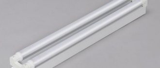
Before checking the RCD for operation, it must be assembled. To do this, we connect the ends of the wire with a plug to the upper terminals, and the ends of the wire with a cartridge to the lower terminals.
To test an RCD with such sensitivity, a light bulb with a power of 20 W will be enough. Screw it into the socket and plug the plug into the socket.
Then turn on the device. To do this, move the “Off” key. on the device to the “On” position If you have assembled and connected everything correctly, the light should light up. It is recommended to repeat this procedure 3-4 times. That is, turn the device on and off.
Then, leaving the RCD on and the light on, press the “Test” button on the device. If the device is working correctly, it should turn off, extinguishing the light. We repeat the procedure 3-4 times, after turning on the device again.
Now we need to check whether the RCD will turn off on its own when a leakage current is generated. We artificially create this leak. We take the free end from the lamp that is not fixed in the terminal block and disconnect it from the RCD. The lamp will go out, but the device will remain on. Then we touch the disconnected wire, for example, to a grounded frame from a circular saw. You can also use any other grounded place so that there is a leak, but it does not harm any device, but goes into the ground. Normally, the RCD is turned off.
Checking the performance of the RCD
There are a total of five methods to check the functionality of this protection, and each of them is available at home:
- Using the button provided by the design of the device.
Using a battery is also a voltage-generating galvanic cell.
- Connecting a resistor – simulates an increase in network resistance similar to that which occurs when the integrity of the electrical network is violated.
- Application of a permanent magnet.
- Using special target equipment.
- We connect the battery in the same way as in any device (minus to the output and plus to the input);
- press “T”, if the device works, it is working.
Each of the proposed methods has its own characteristics, so they should be considered separately.
Standard button
The simplest and fastest method is to check not only a difavtomat, but also a conventional RCD. Each of the devices has a “TEST” or “T” button; in order to press it you do not need to have special skills or special knowledge. Pressing it triggers a reaction simulating a leak in the electrical network. The current strength, which is turned on when the button is pressed, corresponds to the rating indicated on the case (device sensitivity).
The lower the value indicated next to the test button, the more sensitive the device. This must be taken into account when selecting a device for a specific electrical network, because if the device is too sensitive, constant outages cannot be avoided, and if the situation is the opposite, the equipment may burn out.
When you press the test button, a working device will instantly break the electrical circuit and the entire network will be turned off; if after pressing nothing happens, the RCD does not function, that is, there is no protection against breakdowns. The use of such a device is strictly prohibited, because the user is absolutely not protected from current leaks.
It is also worth remembering that modern automatic machines have a controller that will not allow the device to operate when the power supply is disconnected or the supply wires are broken (zero or phase is not important), therefore they need to be checked on a working electrical network. In this case, only the closedness of the electrical network affects the test, and the presence or absence of consumers does not matter. This type of protection is called an electromagnetic RCD; it is designed to protect a person in any situation, including a break in the “zero”.
Battery
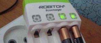
This method is good because it allows you to verify the functionality of the RCD right in the store, without connecting it to the network. To do this, you will need a battery and wires or paper clips to connect it to the machine.
Using the battery method, only electromagnetic RCDs are tested; they are now the most popular, because accurate and reliable. Therefore, there will be no problems with the choice.
The verification algorithm is as follows:
Using this method, you can check both three-phase and two-phase 220 Volt devices. The secret is that the operation of the RCD is based on comparing the potentials at the contacts. Therefore, if you connect even a simple battery, the difference between the input and output potentials should be recorded by the device.
Resistor
This method requires the inspector not only to have a device, but also certain knowledge (the ability to calculate the resistance of a resistor). To do this, a resistor is connected between ground and the outlet terminal. The resistor in this case will play the role of a person struck by current. According to Ohm's law R = U/I. The voltage in this formula is equal to 220 Volts, because we connected one end to the outlet. Next, we connect the multimeter to the resistor and see the “amperage” of the current leakage. Using the formula (as an example 10 mA: 220V/10mA = 22 kOhm) we set the Ohm value required for the test.
This test can also be carried out with a light bulb, with a dimmer connected, instead of a resistor.
Magnet
This method is also applicable to a disconnected automatic machine, because it has nothing to do with electricity. If you introduce a unidirectional magnet into the magnetic field of the electromagnets responsible for arming the machine, it will turn off. The magnetic field simulates resonance, at which the device should turn off. Unfortunately, the method has a drawback - it can only test an electromagnetic RCD.
Special meter
As soon as differential automatic machines appeared on the market, they were followed by the appearance of special measuring instruments. They allow you to check not only the performance of the RCD, but also all other protections, display data on leakage and response time.
The devices are easy to use (you just need to plug them into a power outlet), and the accuracy of the research is comparable to laboratory examination. The only negative is the price of the device; there is no point in buying one for household use, but even for a small enterprise, it will be quite a profitable purchase.
Checking RCDs using current leakage simulation
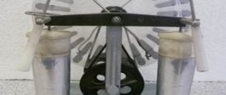
Testing everything in theory is not bad, but using practice is always better. Therefore, you can check the device for operation in a practical way. This method is the most practical, because to implement it you need to assemble a small circuit. The advantages of this method of checking the RCD include the fact that you can see at what leak the RCD actually worked. But there is also a minus, because in such an experiment there is no opportunity to record the shutdown time.
It is necessary to prepare some consumables and instruments to implement this experiment. You need to have with you a regular 10 W lamp, a rheostat, connecting wires, an ammeter, an RCD, and a resistor with a resistance of a couple of kOhms.
At first glance, it may not seem very clear why such a significant set of elements is needed. But each component is really needed. The point of the work is to gradually increase the leakage current, with the help of which it will be possible to observe at what value the RCD will turn off. The rheostat plays the role of precisely the organ with which you can smoothly regulate the current. You can try using a dimmer instead if a classic rheostat is not at hand. A dimmer, in fact, is the same rheostat; it also smoothly changes the current, thanks to which it is possible to change the luminous flux of the lamp. Using these components, a simple circuit is assembled.
To check the device for operation in this case, you need to assemble everything sequentially. It is required to connect the elements with one end to the output of the RCD phase, and the other to the zero input. It is necessary to carefully and smoothly increase the leakage, after which its value is recorded at which the RCD is triggered.
In the photo you cannot see the success of the RCD test, but it ended that way. The RCD tripped when there was a current leak of 10 mA.
If the device does not work when you press the Test button, it may be faulty. Most likely, one of the internal components has failed. The leakage current simulation element itself may break down, but the entire RCD can continue to perform a protective function, even in this state.
Checking the RCD for functionality
To feel safe, you should regularly, at least once a month, check the protective device. You can do this yourself at home. All known verification methods are quite simple and accessible.
Test using the TEST button
The testing button is located on the front panel of the device and is marked with the letter “T”. When it is pressed, a leak is simulated and protective mechanisms are activated. As a result, the device cuts power.
However, under certain conditions the RCD may not work:
- Incorrect device connection. A thorough study of the instructions and reconnecting the device according to all the rules will help correct the situation.
- The TEST button itself is faulty, that is, the device works normally, but the leakage simulation does not occur. In this case, even if installed correctly, the RCD will not respond to testing.
- Malfunctions in automation.
The last two versions can only be confirmed using alternative verification methods.
To ensure that the test mechanism operates reliably, you should repeat pressing the button 5-6 times. In this case, after each network shutdown, you must remember to return the control key to its original position (the “On” state).
Battery test method
The second simple way that you can test the RCD yourself at home for functionality is to use a familiar AA battery.
Such testing can only be carried out with a protection device rated from 10 to 30 mA. If the device is designed for 100-300 mA, the RCD will not trip.
Using this technique, perform the following steps:
- Wiring is connected to each pole of a 1.5 - 9 Volt battery.
- One wire is connected to the input of the phase, the other to its output.
As a result of these manipulations, a working RCD will turn off. The same should happen if a battery is connected to the zero input and output.
Before carrying out such an audit, it is imperative to study the characteristics of the device. If the device is marked A, it can be tested with a battery of any polarity. When checking the AC protective device, the device will respond only in one case. Therefore, if no operation occurs during the test, the polarity of the contacts should be changed.
How to check an RCD with an incandescent light bulb
Another surefire way to monitor the functionality of a protective device is with a light bulb.
To complete it you will need:
- a piece of electrical wire;
- incandescent lamp;
- cartridge;
- resistor;
- screwdrivers;
- insulating tape.
In addition to the items listed, a tool that can be used to easily remove the insulation may be useful.
Incandescent lamps and resistors planned for testing must have suitable characteristics, because the RCD reacts to certain numbers. Most often, a protective device that is purchased for installation in a house or apartment is designed to respond to a leak of 30 mA.
The required resistance is calculated by the formula: R = U/I, where U is the network voltage, and I is the differential current for which the RCD is designed (in this case it is 30 mA). The result is: 230/0.03 = 7700 Ohm.
A 10 W incandescent lamp has a resistance of approximately 5350 ohms. To get the desired figure, all that remains is to add another 2350 Ohms. It is with this value that a resistor is needed in this circuit.
After selecting the required elements, assemble the circuit and, performing the following manipulations, check the functionality of the RCD:
- One end of the wire is inserted into the socket phase.
- The other end is applied to the ground terminal in the same outlet.
During normal operation of the protective device, it is knocked out.
If there is no grounding in the house, the testing method changes slightly. On the input panel, namely in the place where the automation is located, insert the wire into the zero input terminal (marked N and located at the top). Its second end is inserted into the phase output terminal (marked L and located at the bottom). If everything is fine with the RCD, it will work.
Tester test method
The method of checking the serviceability of a protection device using special ammeter or multimeter devices is also used at home.
To complete it you will need:
- light bulb (10 W);
- rheostat;
- resistor (2 kOhm);
- wires.
Instead of a rheostat, you can use a dimmer to check. It is endowed with a similar operating principle.
The circuit is assembled in the following sequence: ammeter - light bulb - resistor - rheostat. The ammeter probe is connected to the zero input in the protective device, and the wire is connected from the rheostat to the phase output.
Next, slowly turn the rheostat regulator in the direction of increasing current leakage. When the protection device is triggered, the ammeter will record the leakage current.
Simulating a leak using an incandescent lamp and a resistor
This technique allows you to simulate real accident conditions. Its difference from the serviceability control with the “Test” button is that the leakage circuit is created not inside, but outside the device. To test a product triggered by a 30 mA leak using this method, you will need:
- 10 W incandescent lamp;
- resistor 2.3 - 2.5 kOhm with power from 5 to 10 W;
- lamp socket;
- insulated wire.
The lamp is connected in series with a resistor, together they create a circuit to simulate leakage. When connected to a 220V network, a current flows through a lamp with a resistor sufficient to trigger the protection (0.025-0.029 A). Since the resistance of an incandescent lamp may vary in one direction or another, the resistance of the resistor will require adjustment.
One of the wires of the test circuit is connected to the grounding contact of the socket, and the other to the phase of the same socket. If the protection works, it will instantly disconnect the outlet from the network. This technique allows you to additionally test all sockets in an apartment or office and identify those where unscrupulous installers did not connect the grounding contact.
If the sockets do not have a grounding contact, the test is carried out directly in the distribution panel by touching the phase output of the RCD and the “PE” or “PEN” bus. All three methods have one common drawback - they do not allow you to determine the magnitude of the operating current. To do this, the circuit with the light bulb needs to be modified.
The second way to check the RCD is using a test lamp
Anyone can check and make sure that the RCD is technically sound and its operation is carried out correctly with sufficient practical reliability.
An RCD, as you know, is triggered when a leakage current appears, so using a regular lamp and resistances we will now create this leakage.
So, to check the RCD you need the following tools:
- – a piece of electrical wire;
- – electric lamp (the best option would be an incandescent lamp with a power of 10-15 W);
- – socket for an electric lamp;
- – several resistances;
- – power tools (screwdriver, side cutters, electrical tape, etc.).
First, let's calculate how much current flows through the lamp, i.e. what leakage current can we create? The current through the lamp is calculated using the following formula: I=P/U. Where P is the power of our lamp, and U is the network voltage.
For example, for a 25 W lamp we obtain a test differential leakage current equal to 114 mA. Of course, the lamp test will be very rough, since we have an RCD rated at 30 mA, and we are passing more than 114 mA through it. This is definitely not good.
A lamp with a power of 10 W will have a resistance of about 5350 Ohms. The current that will flow through the lamp is approximately 0.043 A (43 mA). This is a large current to test our 30 mA ouzo, so we need to somehow reduce it. This can be done by adding resistance.
The data sheets say that the residual current device should operate at 30 mA leakage. In reality, tripping occurs at lower currents at about 15-25 mA.
I propose to assemble a circuit in which the current will be the same as the differential current for which the RCD is designed, that is, 30 mA. Using well-known formulas from a physics course, you can calculate what resistance should be in the circuit: R=U/I = 230/0.03 = 7700 Ohms.
That is, in order for a current of 30 mA to flow through a 230 V network, the resistance must be 7.7 kOhm. The resistance of the lamp itself is already 5.35 kOhm, we still need to add 2.35 kOhm. Such resistance can be purchased at any amateur radio store; it is not expensive.
I already had several 5 W resistors with a resistance of 4.7 kOhm, I decided to use them. But if you connect such a resistor in series with a 10 W lamp, it will certainly burn out, since it is not designed for such a load (the lamp is 10 W, therefore the resistor must be of the same power).
However, if two such resistors are connected in parallel, then their total power will be exactly 10 W, and the resistance of this circuit will be 2.35 kOhm.
Now, using wires, we connect these resistances in series with our lamp.
How to check the RCD for tripping using such a device? If you have a protective zero connected to the sockets in your house, then you can check the RCD for tripping in each socket.
To do this, it is enough to connect one end of the wire of our device to a phase in the socket, and touch the other to the protective zero. The residual current device should trip.
If your sockets are connected without a protective zero (in most cases this is the case), then you won’t be able to check every socket here (unless you pull a single-core wire from the switchboard into the apartment).
In this case, you can check the functionality of the uzo only in the electrical panel where it is installed. To do this, we connect one end of the device to the zero input terminal of the RCD and connect the other end to the phase output (indicated by 2).
If you have a question, why is there a light bulb in this circuit at all? In order to visually see that there is current. Of course, it will work, as they say, at half-heat, but it will still be visually visible that current is passing through it and there is a leak.
For example, let's remove the light bulb from the circuit. What happens if the resistance is damaged (you can’t tell visually whether it’s working or not). In this case, when checking the functionality of the RCD, no current will flow past it and you can mistakenly come to the conclusion that the RCD is faulty.
Testing with the device
In factories and laboratories, where periodic testing for all devices is mandatory, a special device is used to test the RCD.
An example of such a device is the PZO-500, PZO-500 Pro, MRP-200 and other professional devices. They allow you to check the parameters of RCDs of various types, with different differential current limits, without additional circuits.
Professional meters are used where regular, for example, monthly checks of all existing RCCBs are practiced, and there are high requirements for accuracy and reliability. Such devices are quite expensive, so their use for domestic purposes is irrational.
What is being checked
Protection against damage
To explain what parameters must be monitored during testing of circuit breakers with differential current difference monitoring, let us recall that the main task of the RCD is not only to detect emergency current leakage, but also to turn off the power before irreversible damage occurs.
In this connection, GOST R 51327.1-2010 provides a complete list of characteristics used for expert assessment of the performance of the device.
Some of them are used for factory certification and certification, but for operational control the following data is required:
- rated voltage and current;
- standard disconnecting differential current;
- standard non-disconnecting differential current;
- shutdown time.
Separately, we emphasize that the nominal shutdown time for RCDs is in the range from 0.04 to 0.3 seconds, and even a small deviation from these values can nullify all efforts to install protection.
Shutdown time
Obviously, such values can be recorded only with the help of automatic measuring equipment, therefore, the list of ETL equipment, as a rule, includes a special device for checking the functioning of the RCD, and methodological instructions are written taking into account its technical features.
The most typical representative of this group of meters is the MRP 200 device.
In addition to technical characteristics, when testing RCDs, the following accompanying factors must be recorded:
- correct installation of the device;
- correctness of the circuit connection;
- general performance.
When checking the correct installation, special attention should be paid to the following factors:
- correspondence of phases and terminals;
- correct switching of neutral and grounding conductors.
In this case, monitoring of overall performance means the following actions:
- visual and mechanical check of the switch lever;
- confirmation of operation when pressing the test button.
Trigger current measurement
The following are added to the list of components for implementing the previous method:
- rheostat;
- multimeter or ammeter with a measurement range of 1-30 mA.
A light bulb, resistor, rheostat and multimeter are connected in series. The connection diagram for simulating a leak does not change. The testing technique is based on a smooth change in the leakage current from zero to the response value. Initially, the rheostat is fully inserted; its resistance at the start of the test should be maximum. Then the rheostat slider smoothly moves in the direction of decreasing resistance. In this case, the readings of the multimeter are monitored. The value at which the shutdown occurs is fixed; it should not exceed 30 mA. To test devices that operate at 10, 100, 500 mA using a lamp, it is necessary to select the resistance of the resistor. The limit also needs to be changed. Do not forget about the safety rules: all wires must have proper insulation, contact connections must be insulated. If your experience is not enough to conduct such tests, it is better to refuse them.
You should not test the functionality of the protection on yourself by deliberately touching live wires or contacts. If it turns out to be faulty, it could cost you your life. Even if a shutdown occurs, you will have time to receive an electric shock. None of the described methods is capable of measuring the protection response time. How do specialists check RCDs?
Reasons for tripping the RCD
It turns out there are many reasons for the triggering:
- There was actually a leak in the electrical network. This may be due to the fact that the wiring in the apartment is old and has worn out over time, dried out, and some areas have become exposed. If the wiring was recently installed and the quality of the connections leaves much to be desired, or the power line was damaged during the electrical installation.
- The reason may be electrical equipment that is part of this wiring and is protected by this RCD. In this case, there may be either damage to the wire of this equipment or internal malfunctions. For example, the motor winding is broken.
- The safety device may have been installed incorrectly, which is why it does not work properly and sometimes trips.
- When buying an RCD in a store, the wrong choice was made, and the device does not meet the technical specifications.
- Defective protective device. So, the Test button may be stuck, or the trigger mechanism, which constantly turns off the power line at the slightest vibration, is faulty.
Reasons for frequent operation may include: incorrect location of the RCD in the power line; connection of the neutral conductor and grounding; High air humidity in the apartment contributes to frequent shutdown of the mechanism.
Triggering of the RCD occurs due to unfavorable weather conditions. If the distribution board is located outside in rainy weather, the RCD may turn off, as well as if water gets into the electrical appliance.
The principle of checking the performance of an RCD
When a material is tested for strength, they try to break it. To test circuit breakers, it is necessary to create conditions under which they will work - all existing tests are carried out according to these rules.
The residual current device trips if it detects a current leak, i.e. when more current is supplied to an electrical circuit through the phase wire than comes out of it through the neutral wire. Connecting an RCD can be done in houses with or without grounding - to carry out checks, you need to understand the difference between these methods of protecting household appliances and people.
- In the first case, if the wiring insulation is broken, then part of the current goes to the body of the electrical appliance, from where it immediately goes to the ground wire, as a result of which a leak occurs, which the residual current device immediately registers and opens the circuit.
- If there is no grounding, then if the insulation is damaged, the current again enters the body of the electrical device, but since it has nowhere else to go, then in general the balance between the input and output is maintained and the RCD does not yet trip. A leak will be detected only if a person touches a faulty electrical appliance - current will flow through the body, the balance between the incoming and outgoing current in the main circuit will be disrupted and the RCD will immediately turn off the power.
Of course, if there is no grounding, then checking the functionality of the RCD by touching the phase wire is, to put it mildly, a very extreme method - if suddenly the device is faulty, then a noticeable electric shock is inevitable.
Despite the difference in connection methods, the operating principle of the residual current device remains unchanged and all methods for testing the device are suitable in both cases. In this case, the installed automatic circuit breaker is checked in exactly the same way, because it is the same RCD, only combined in one housing with a circuit breaker.
Why is the RCD tested with a battery?
There are two main types of residual current devices - one involves the use of a transformer exclusively, which responds to differential current, while the other requires additional power to connect an amplifier, which provides more accurate responses.
The first type is called electromechanical, and the second is called electronic. They are equally effective when there is power in the circuit, but it is best to be aware of what accessories are installed in your system.
This is why you need to check the RCD with a battery - it is carried out in a few minutes and is absolutely safe, unlike many other tests.
Example of a technical report
Back
Forward
RCD testing method: step-by-step diagnostics
If the protective device is faulty, unpleasant consequences can be expected. A timely check will help to identify the fact of a malfunction of the RCD. The method is also suitable for checking a differential automaton (difavtomat).
The RCD must be checked immediately after its installation, as well as once a month. According to the rules, the check must be carried out in accordance with the rules that are prescribed in the technical recommendations for the device. A full check includes a number of steps.
Step by step check:
- Check the control lever.
- Run the button tester.
- Measure the setting current.
- Check the response time of the RCD.
Inspections must be carried out at regular intervals. Simple checks using light bulbs can be carried out once a month. Modern devices may have a built-in video recorder or radar detector, which will allow you to find out about a current leak much faster. You can independently check the operation of the Uzo with a multimeter. A simple tester can be purchased at the store. To check, you can make a circuit using a battery and a light bulb
It is very important to be responsible about the frequency of checks or their quality, since failure of the device can lead to dire consequences
Methodology for checking RCDs with a battery
First of all, the device must be dismantled and installed in the cocked position. Then a suitable battery is found - a standard 9 V finger-type product is best suited, although using a 12 V “Krona” would not be a mistake. Next, checking the RCD with a battery involves connecting the plus to the top contact, the minus to the bottom. The result should be an operation with a slight delay, which is caused by the propagation of the induction current in the control winding of the transformer used. If this happened, the electrical work was carried out using electromechanical models. You can see the principle of connecting contacts in the following photo:
If the result is negative, try swapping the battery contacts. If the operation occurs, then you are the owner of an “AC” type device, which has unidirectional polarity. When triggered in two directions, they speak of the presence of type “A”, which is more universal. An ineffective test of the RCD with a battery indicates that this is an electronic protective device. Of course, it is additionally worth checking the functionality of the RCD with the voltage turned on - it is possible that the device has simply failed.
Checking the RCD using a control lamp
Anyone who cares about their safety should carry out a control check of the correct operation of the RCD at least once every few months. You can check the operation of the RCD yourself using a practical and reliable method. The device works in such a way that when a current leak occurs, it is triggered.
To check the device in this way, you will need an electric wire, an electric incandescent lamp, a socket, resistances and special electrical tools. Before creating a leakage, it is necessary to calculate how much leakage current can be created. It depends on the current that flows through the electric lamp.
How to check the operation of an RCD using a lamp:
- Connect two resistors in parallel. For their power to be 10 W, the resistance must be 2.35 kOhm.
- Using wires, these connections are connected to an electric lamp.
- If there is a protective zero connection to the sockets in the room, then you can check the operation of the RCD using any socket.
- One wire must be connected to the phase, the other wire must touch the protective zero.
As soon as the action is completed, the device should work instantly. If there is no protective zero in the sockets, then checking each socket will not be possible. If this is the case, you can check whether the RCD is working through the electrical panel.
Checking the RCD using a test lamp
One way to check the functionality of an RCD is to use a test lamp. Together with resistance, it successfully simulates current leakage and allows you to obtain reliable information. To carry out the test, you will need a piece of electrical wire, a 10-15 watt incandescent light bulb, a light bulb socket, resistors and the necessary power tools.
Before starting the test, it is necessary to calculate the leakage current that will be created. For this, there is a formula that determines the current strength: I=P/U , in which P is the power of the light bulb, and U is the network voltage. For example, with a lamp power of 25 watts, the simulated differential leakage current will be 114 mA. For an RCD with a rated current of 30 mA, this is not suitable since the test will be rough and of poor quality.
It is necessary to use a 10-watt lamp through which a current of 43 mA will flow. By adding the necessary resistance to equalize the currents as much as possible, you can test the RCD.
Where to start checking the performance of the RCD
Various devices or materials are subjected to extreme situations during testing to ensure their reliability. Therefore, it is necessary to create an imitation of the conditions for tripping the RCD. Due to this, all checks are carried out.
Next, we’ll figure out how to check the RCD in various ways. The device is triggered if a current leak occurs due to the fact that more voltage flows through the phase than comes out from the zero side.
But it is necessary to separate the installation with and without ground, since the check will be different:
In the first option, if the insulation of the electrical wiring is broken, part of the voltage is transferred to the body of the electrical device and directed through the grounding - a leak is formed and the RCD is triggered;
If there is no grounding, the voltage is transmitted to the surface of the body of the electrical device, since there is no passage for it, this maintains full balance. The device cannot yet operate, but when a person touches the surface of the faulty device, the protection will immediately activate. This is due to the fact that current will flow through the body and this will destroy the balance in the network.
How to check the performance of an RCD
Now let's look at various ways to test an RCD for operation, since it is necessary to make sure that the device is working before using it. We recommend that you carry out various checks regularly, since the correct operation of the RCD is not constant and may become disrupted over time.
Checking using the test button is considered the simplest and most accessible way:
- It is located on the front side and is usually indicated in a characteristic way;
- After pressing the button, additional resistance is created - the protection will work.
Sometimes pressing the test button may not work, which in itself is dangerous. But the device may work normally because of this, this option is not considered the only correct way to check.
And what to do if the test button does not work - there are several options:
- With a recent connection, the RCD may have been installed incorrectly;
- When this is not the problem, and the protection previously responded to such testing, then a full check of the device and the correctness of its connection is carried out;
- Sometimes after checking it becomes clear that the RCD is working properly, but your own testing does not work. Continued use is allowed, but we recommend replacing the device, since there is some problem in it and it may manifest itself a little later;
- If various tests have proven that the RCD is not working correctly, it must be replaced.
Important: We recommend checking the RCD using the “Test” button at least once a month, as this will protect you from various serious problems arising from a short circuit.
But there are other ways to test the performance of a device. For one of them you will have to use a battery. With its help, a situation similar to a current leak is created and the RCD should trip. But in reality there will be no such leak.
It is difficult to identify the best verification methods, but this one is considered the simplest and safest in comparison with analogues. How to do it:
- All wires of the device in use must be disconnected;
- Wires are connected to the terminals of either pole for testing using a battery;
- The wires are stripped and brought to the plus and minus surfaces on the side of the battery. If the RCD is working properly, then its protection will work.
But for the method to work, it is necessary to take into account important points. Let's look at them in detail:
- A sufficient level of battery power is required so that it turns out to be higher than or equal to the value to which the RCD protection reacts;
- Correct polarity must be taken into account for the connection to work. If nothing happens you will have to change the polarity. Again, nothing works, this may indicate a malfunction. But there is another nuance: the device may have an electronic control system.
Now you know how to properly check the RCD using various methods and what it serves. This information can protect your network from unpleasant situations leading to disastrous consequences. Although there are other verification options, they differ in a more labor-intensive process.
Use of sandstone- Assorted restaurant equipment
- Importance of Waste Management in Business
We have offered you the simplest and most accessible testing of RCD performance, and we believe that this is sufficient in most cases. But, if for various reasons they do not give the required result, you can use advanced testing options or contact an electrician if your own knowledge is not enough.
Testing with a AA battery
A very simple method is to check the RCD using a AA battery. It allows you to check the functionality already during the purchase of the device.
To directly carry out testing, a piece of wire with a length of at least 10 centimeters is connected to any pole of the device. The second wire is connected at the bottom of the device during manufacture. After this, the AA battery is brought to both wires.
When the wires touch plus and minus, the RCD should trip. If this does not happen, you need to reverse the battery poles and repeat the test. If the device is working properly, the shutdown lever should be knocked out.
Checking with the “Test” button
Many models from leading manufacturers are equipped with a built-in performance tester that allows you to simulate current leakage. It is turned on by the “T” or “Test” button on the device body.
The methodology for such testing is as follows. First you need to connect the RCD to a test bench or network and make sure the quality of the connection. Then apply operating voltage to the RCD and press the “Test” button at least 5 times. The device should work 5 times out of 5.
This check is considered sufficient for a device serving the home electrical network. The “Test” button turns on a circuit built into the RCD that artificially creates a current leakage of such a magnitude that the device should operate. The quality of the test does not depend on the fact of the presence of a load - that is, working devices or lamps.
How to check the RCD using the “TEST” button
When checking the RCD using the “TEST” button, a resistor installed between the neutral and phase contacts is connected. If the residual current device is working properly, it will turn off. Such a check must be carried out every quarter, that is, at least once every three months.
At the same time, a significant drawback of such a test is the need to connect the RCD to a 220 Volt network. We will look at ways to test the device without connecting to the home power supply.
The third way to check the RCD is to simulate a current leakage
Theory, as they say, is good, but practice is more interesting. Therefore, in this section we will consider an example of how to test an RCD for operation in a practical way.
This method is the most practical in this article, since to implement it you need to assemble a small circuit. The advantage of this method of checking the RCD is that we will see at what leakage the residual current device actually worked. However, there is a minus: in this experiment there is no way to record the shutdown time.
To implement this experience you will need:
- – a regular 10 W lamp;
- – resistor with a resistance of 2 kOhm;
- – rheostat;
- – ammeter;
- – residual current device;
- – connecting wires.
At first glance, it may not seem clear why such a set of elements is needed. I'll explain everything in order. The point of all the work is to gradually increase the leakage current and see at what value the RCD will turn off. The rheostat serves as the organ with which you can smoothly regulate the current.
But I didn’t have a rheostat, but I did have a dimmer (dimmer), so I used it in the circuit instead of a rheostat. And what? A dimmer is the same rheostat, it also smoothly changes the current, due to which the luminous flux of the lamp changes.
With the help of all these elements, a simple circuit is assembled, similar to what was assembled above (a test lamp with a resistance), only in addition there is a rheostat and an ammeter.
How to check the RCD for operation in this case? All elements are assembled in series and connected at one end to the phase output of the residual current device and the other to the zero input. By gradually increasing the leakage current, it is necessary to fix its value at which the residual current device will operate.
It is not visible in the photo, but the RCD test was successful. The RCD of the VD1-63 series from IEK with a rated differential current of 30 mA tripped with a leakage of 10 mA.
What should I do if pressing the TEST button does not turn off the residual current device?
If the residual current device does not operate when the “Test” button is pressed, then this is evidence of a malfunction of such a device, namely a malfunction of one of its internal mechanisms.
One of those cases when the RCD test does not work is a malfunction of the leakage current simulation mechanism itself. In this case, the RCD can continue to perform its protective function, even despite the existing malfunction.
However, it is still recommended to replace such an RCD, since there is no confidence in its reliable and long-term operation. Human life is still worth more. Moreover, the price for an RCD is not so unapproachable (approximately 600 - 1000 rubles / piece).
Method No. 1 - TEST button
The easiest way to check the RCD for operation with your own hands is to use the TEST (“T”) button installed on the front panel, as shown in the photo below. In this case, you just need to press the button with your finger, as a result of which a leakage current will be simulated and the protection should work.
If after pressing the tester the shutdown does not occur, this indicates the following:
- You may have made the connection incorrectly, as the test result showed. In this case, we recommend that you read the instructions for connecting a residual current device yourself.
- The button doesn't work. It happens, it happens that the RCD itself works, but the leakage current simulation is faulty. In this case, even if the connection is correct, false positives will not occur during testing. You will need to check the protection yourself using one of the alternative methods that we described below.
- The automation is faulty. Again, it will be possible to verify whether the RCD is working or not only after another, more complex check.
Video instructions for checking for serviceability yourself
First way
Checking the ouzo using the appropriate button is very simple and straightforward. This is the TEST button. It’s easy to find - it’s located right on the device’s body, marked with a large letter “T”.
The advantages of this method include:
- Safety
- There is no need for special knowledge or qualifications - the test can be performed by an ordinary user who is not familiar with the basics of electrical engineering.
The button, in fact, emits the risk of current leakage, its passage past the RCD. It is noteworthy that the nominal value is set automatically - by a resistor value. Immediately after pressing the button, the device is activated, but only if its connection is made according to all the rules. Of course, the device itself must be in good working order. The RCD will definitely work, regardless of the conditions - there may not even be a load connected to it.
How to check an RCD at home?
Checking the RCD by pressing the “test” button
The most common and safest way is to check the functionality of the RCD using the “Test” button located on the body. This type of testing does not require special knowledge and can be performed independently by anyone. The button itself is indicated by a large letter “T” or the word “TEST”. With its help, cases of current leakage past the RCD are simulated.
The leakage current rating is set by a special test resistor built into the device. The current flowing through it should not exceed the value of the differential current for which the device itself is designed. Based on this, a resistor with the necessary parameters is selected. If the connection to the electrical network is correct, the RCD is triggered immediately after pressing the testing button, regardless of the presence or absence of a connected load. For everyday conditions, such a check is considered quite sufficient.
The recommended frequency of inspections is once a month. The effectiveness of the tests is achieved by simulating a real current leak, to which the device responds by instantly shutting down.