It is in every computer, laptop and set-top box. It does not affect your frame rate or Bitcoin mining. It doesn't have billions of transistors, and it doesn't use the latest semiconductor processes. Sound boring? Not at all! Without this thing, our computers would do absolutely nothing.
PSUs, aka power supply units (English PSU, Power Supply Units), do not blow up the headlines like the latest processors, but they are interesting technologies that deserve our attention. So put on your white coats, masks, gloves and let's start opening up our humble little guy - the power supply, let's take it apart and look at what each of its organs does.
And yes, quite recently we figured out how to choose the right power supply. Recommended reading.
What is it and what is it eaten with?
Many computer components have names that require a bit of technical knowledge to understand what they are and why (for example, a solid-state drive), but in the case of a power supply, everything is pretty obvious. This is the unit that provides power.
But we cannot put an end to this, proudly declaring “the article is ready.” Our series of articles is devoted to the internal structure, and on the operating table we have a test subject - the Cooler Master G650M. This is a fairly typical representative, with characteristics similar to dozens of other models, but it has one feature that is not found in all power supplies.
Official photo of the Cooler Master power supply.
This is a standard size power supply that fits the ATX 12V v2.31 form factor, making it suitable for many computer cases.
There are other form factors - for example, for small cases, or completely unique ones upon special order. Not every block corresponds to the exact dimensions established by standard form factors - they may be the same width and height, but differ in length.
This power supply from Cisco is specially designed for server racks
PSU markings usually indicate their main parameter - the maximum power provided. In the case of our Cooler Master, this is 650 W. Later we will talk about what this actually means, but for now we will just note that there are also less powerful power supplies, since not all computers require exactly that much, and some need even an order of magnitude less. But still, most desktop computers are provided with power in the range from 400 to 600 W.
Power supplies like ours are assembled in rectangular, often unpainted, metal cases, which is why they are quite heavy. Laptops almost always have an external power supply, in a plastic case, but its internals are very similar to what we will see in the power supply we are considering.
Photo source nix.ru
Most typical power supplies are equipped with a power switch and a cooler for active thermal regulation, although not all power supplies need it. And not all of them have a ventilation grill - in server versions, in particular, this is rare.
Well, as you can see in the photo above, we are already armed with a screwdriver and are ready to start opening our copy.
Adjustable switching regulator
The switching stabilizer circuit is assembled on a fairly well-known and affordable DC/DC converter microcircuit - MC34063.
It will be interesting➡ How to choose a flux for soldering microcircuits
To make it clear. The MC34063 chip is a specialized PWM controller designed for pulsed DC/DC converters. This chip is the core of the adjustable switching regulator used in this power supply.
The MC34063 chip is equipped with a protection unit against overload and short circuit in the load circuit. The output transistor built into the microcircuit is capable of delivering up to 1.5 amperes of current to the load. Based on the specialized MC34063 chip, you can assemble both step-up and step-down DC/DC converters. It is also possible to build adjustable pulse stabilizers.
Features of pulse stabilizers
By the way, switching stabilizers have a higher efficiency compared to stabilizers based on microcircuits of the KR142EN series (KRENKI), LM78xx, LM317, etc. And although power supplies based on these microcircuits are very simple to assemble, they are less economical and require the installation of a cooling radiator .
Efficiency
The MC34063 chip does not require a cooling radiator. It is worth noting that this chip can often be found in devices that operate autonomously or use backup power. The use of a switching stabilizer increases the efficiency of the device, and, consequently, reduces power consumption from the battery or battery. Due to this, the autonomous operating time of the device from a backup power source increases.
I think it’s now clear why a pulse stabilizer is good.
A little theory
But before we start digging into the internals, let's ask ourselves, is a power supply really that necessary? Why can't you plug your computer directly into a power outlet? The answer is that computer components are designed for a completely different voltage than the mains voltage.
The graph below shows what the grid electricity should be (US = blue and green curves; UK = red curve). The X axis represents time in milliseconds, and the Y axis represents voltage in volts. The easiest way to understand what voltage is is by looking at the energy difference between two points.
If a voltage is applied to a conductor (such as a metal wire), the difference in energy will cause electrons in the conductor material to flow from a higher energy level to a lower one. Electrons are the constituent atoms that make up a conductor, and metals have many electrons that can move freely. This flow of electrons is called current and is measured in amperes.
A good analogy is with a garden hose: voltage is akin to the pressure you use, and water flow is akin to current. Any restrictions or obstacles in the hose are essentially like electrical resistance.
We see that the electricity in the network varies over time, which is why it is called alternating current voltage (AC, alternating current). In the US, line voltage varies 60 times per second, peaking at 340 V or 170 V, depending on location and connection method. In the UK the peak voltages are lower and the frequency of these fluctuations is also slightly different. Most countries have similar mains voltage standards, with only a few countries having lower or higher peak voltages.
The need for a power supply is that computers do not work with alternating current: they need a constant voltage that never changes, and also much lower. On the same graph it will look something like this:
But a modern computer requires not one constant voltage, but four: +12 volts, -12 volts, +5 volts and +3.3 volts. And since these values do not change, such a current is called constant (DC, direct current). Converting current from AC to DC (so-called rectification) is one of the main functions of the power supply. It's time to open it up and see how he does it!
Converting current from AC to DC is one of the main functions of PSU. It's time to see how he does it!
Here we must warn you that the power supply contains elements that accumulate electricity, including deadly electricity. Therefore, disassembling the PSU is potentially dangerous.
Official photo of the Cooler Master power supply.
The principle of operation of this power supply is similar to many others, and although the markings on various parts inside will be different, this does not make any fundamental differences.
The power cord connector is in the top left corner of the photo, and the current essentially flows clockwise until it reaches the output of the power supply (bundle of colored wires, bottom left corner).
Photo source
techspot.com
If we turn the board over, we can see that compared to the motherboard, the conductors and connections on it are wider and more massive - this is because they are designed to handle higher currents. Also, a wide stripe in the middle catches your eye, like a river flowing across the plain.
This again suggests that all power supplies have two clearly separated nodes: primary and secondary. The first is to adjust the input voltage so that it can be effectively stepped down; the second is all the settings for the already rectified and reduced voltage.
Filtration
The first thing the power supply does with mains electricity is not rectification or reduction, but equalization of the input voltage. Since our homes, offices and businesses have many electrical devices and appliances that constantly turn on and off, as well as emitting electromagnetic interference, alternating current in the network is often “lumpy” and with random surges and drops (the frequency is also not constant). Not only does this make it difficult for the power supply to carry out conversions, but it can damage some of the components inside it.
Our power supply has two stages of so-called input filters (transient filter), the first of which is built directly at the input using three capacitors. It performs a role similar to that of a speed bump on the road - only instead of speed, this filter dampens sudden surges in input voltage.
Photo source techspot.com
The second filter stage is more complex, but essentially does the same thing.
The yellow bricks are again capacitors, but the green rings wrapped in copper wire are inductive coils (although when used in this way they are usually called chokes). The coils accumulate electrical energy in a magnetic field, but the energy is not lost and is smoothly returned due to self-induction. Thus, a suddenly appearing high pulse (jump) is absorbed by the magnetic field of the inductor in order to give an even voltage at the output without any jumps.
The two small blue disks are another representative of the capacitor variety, and just below them (green, with long legs covered with black insulators) is a metal oxide varistor (MOV). They are also used to protect against input voltage surges. You can read more about the different types of input filters here.
Photo source techspot.com
From this power supply unit you can often determine how much the manufacturer has saved, or what budget class the device belongs to. Cheaper ones will have simplified input filtering, and the cheapest ones will not have it at all (avoid these!).
Now that the tension has been leveled and combed, he is allowed to move on - in fact, to transformation.
What is a power supply and what is it used for?
Power supply (aka PSU) is a power source in the system unit, which is responsible for providing energy to the remaining components. The durability and stability of the entire system largely depends on the power supply. In addition, a computer power supply prevents the loss of information from a personal computer, preventing energy surges.
I am sure that every person who is more or less familiar with technology knows that a personal computer runs from a power outlet. However, not every user is aware that system components cannot receive energy directly. This is how we smoothly come to the most interesting thing: what is a power supply for in a PC? For two reasons:
- Firstly, the current in the electrical network is alternating, which computers really don’t like. The power supply makes the current constant, correcting the situation;
- Secondly, each component of a PC, and even a laptop, requires a different voltage. And again the power supply comes to the rescue, supplying the processor and video card with the necessary current.
Conversion
As we said, the power supply needs to change the AC voltage, which in American outlets is usually around 120 volts (technically, this is 120 volts rms, but we won’t break our tongue like that), giving the output a constant voltage of 12, 5 and 3. 3 volts.
The first step is to convert AC to DC, and our unit uses a bridge rectifier for this. In the photo below it is a flat black element glued to the radiator.
Photo source techspot.com
This is another place where the power supply manufacturer can cut costs, since cheaper rectifiers perform worse (eg run hotter). Now, if the peak input voltage is 170 V (which is the case for a 120 V network), then after passing through the rectifier bridge, it will become 170 V, but already DC.
In this form, it enters the next stage, and in our block it is an active power factor correction module (APFC or Active PFC, Active Power Factor Correction converter). This unit also stabilizes the voltage, smoothing out “dips” due to storage capacitors; In addition, it protects against output power surges.
Passive correctors (PPFC or Passive PFC) do essentially the same job. They are less efficient, but good for low-power power supplies.
Photo source techspot.com
The APFC in the photo above is represented by a pair of large cylinders on the left - these are capacitors that accumulate equalized current before sending it further along the chain of processes in our power supply.
Behind the APFC there is a PWM, pulse width modulator (PWM, Pulse Width Modulator). Its purpose is to convert direct current back to alternating current using several fast-switching field-effect transistors. This needs to be done because in the next step a step-down transformer awaits us. These devices, based on electromagnetic induction, consist of two windings with different numbers of turns on the metal core needed to step down the voltage, and operate transformers with alternating current only.
The frequency of the AC current (the rate at which it changes; in Hertz, Hz) greatly affects the efficiency of the transformer - the higher the better, so the frequency of the original 50/60 Hz supply increases by about a thousand times. And the more efficient the transformer, the smaller its size. This type of device that uses these ultra-fast DC frequencies is called a Switched Mode Power Supply (SMPS).
In the photo below you can see 3 transformers - the largest one has 12 volts at its only output, and the smaller one has 5 volts (we'll talk about it a little later). In other power supplies you can find one large transformer for all voltages at once, that is, with several outputs. And the smallest transformer is designed to protect PWM transistors and suppress its interference.
| Photo source techspot.com
You can implement in different ways obtaining the necessary voltages, PWM protection, and so on. It all depends on the budget segment and the power of the device. However, everyone equally needs to remove the voltage from the transformers and straighten them again.
In the photo below we see an aluminum heatsink for the low-voltage diodes that perform this rectification. And also, specifically in this PSU, we see a small additional board in the center of the photo - this is a node of voltage regulation modules (VRM, Voltage Regulation Modules), providing outputs of 5 and 3.3 volts.
Photo source techspot.com
And here we should talk about what pulsation is.
In an ideal world, with ideal power supplies, alternating current will be converted into absolutely smooth, without the slightest fluctuation, direct current. In reality, such 100% accuracy is not achieved, and the DC voltage has, albeit minor, fluctuations.
This effect is called ripple voltage, and in our power supplies we like to keep it as low as possible. Cooler Master does not provide information about the ripple voltage value in the specification for our experimental PSU, so we resorted to third-party testing results. One such analysis was performed by JonnyGuru.com and they found that the maximum ripple voltage of the +12V output was 0.042V (42 millivolts).
The graph below shows the deviation of the actual voltage received (blue curve; its shape, of course, is not such an ideal sine wave - after all, the ripple itself is not constant) from the required flat voltage of +12 V DC (red straight).
This deviation is largely the responsibility of the capacitors throughout the PSU. Low-quality, cheap capacitors lead to an increase in this unnecessary ripple. If it is too large, then some electronic components of the computer that are most sensitive to power quality may begin to work unstable. Fortunately, in our example, 40-plus millivolts is normal. Not great, but not bad either.
But the matter does not end with obtaining acceptable output voltages. It is necessary to ensure control of the outputs so that the power at each of them is always full and stable, regardless of the power of the loads at other outputs.
Photo source techspot.com
The chip you see in this photo is called a supervisor and it makes sure that the pins do not have too high or low voltage and current. It works simply - it simply turns off the power supply when such problems occur.
More expensive PSUs can be equipped with a digital signal processor (DSP), which not only monitors voltages, but can also adjust them if necessary, and also send detailed data about the state of the power supply to the computer using it. For the average user, this function is quite controversial, but for servers and workstations it is highly desirable.
Power supply power calculation
In order for the power supply to work reliably and ensure comfortable work at the computer, it is necessary to calculate in advance the optimal power . In order to determine it correctly, on the Internet on specialized resources you can find a calculator for calculating the power of the power supply. However, this option is not optimal for everyone. Many people use simple mathematics to determine the desired characteristic. The method itself is to calculate the total energy consumption of the components that are present in the system unit.
By adding up all the values, you can get the power of the power supply, which will ensure stable operation of the “machine”. When choosing a power supply, you should know that the maximum power of the selected device must be greater than the total power consumption of all components included in the system.
Typically the power consumption of the components present in a PC is as follows:
- CPU. It consumes 50-120 W. It should be understood that the more powerful the chip is in your computer, the greater the energy consumption will be;
- motherboard. It consumes 15-30 W. Its energy consumption increases with increasing functions;
- video card. It requires 60-300 W;
- RAM. The energy consumption of this component is 15-60 W.
- HDD. It consumes the same amount of energy as RAM. However, here everything depends on its characteristics, as well as the load placed on it.
- CD-DVD drive. This component of the system unit consumes 10-25 W. Here everything depends on the maximum disk rotation speed, as well as the operating mode;
- sound card. This element of the system unit requires energy in the amount of 5-50 W;
- fans. One cooler requires 1-2 W to operate. Here everything depends on the rotation speed, as well as the number of fans and their dimensions.
Exits
All power supplies come with long bundles of wires sticking out from the back. The number of wires and available connectors for powering devices will vary from model to model, but some standard connections should be provided by all power supplies without exception.
Since voltage is the magnitude of the potential difference, each output has two wires: one for the specified voltage (for example, +12 V) and a wire against which the potential difference is measured. This wire is called the ground, "earth", "reference wire" or "common" wire, and these two wires form a loop: from the power supply to the consumer device, and then back to the power supply.
Because some of these closed loops carry small currents, they may share common ground wires.
Official photo of the Cooler Master power supply.
The main required connector is the 24-pin ATX12V v. 2.4, which provides main power via several pins of different voltages, and also has a number of special pins.
Of these special ones, we note only the “+5 standby” pin – standby power supply for the computer. This voltage is always supplied to the motherboard, even when the computer is turned off, provided that it remains plugged in and its power supply is working. The motherboard needs standby power in order to remain active.
Most PSUs also have an additional 8-pin motherboard connector with two +12V lines, and at least one 6 or 8-pin power connector for PCI Express.
The PCI Express slot can handle a maximum of 75W of graphics cards, so this slot provides additional power for modern GPUs.
Our particular power supply in question actually uses two PCI Express power connectors on the same lane for cost reasons. Therefore, if you have a really powerful video card, try to allocate an independent power line for it, do not share it with other devices.
The difference between 6 and 8-pin PCI Express connectors is two additional ground wires. This allows you to increase the current, satisfying the needs of the most power-hungry video cards.
Over the past few years, we have increasingly begun to notice power supplies proudly labeled “modular” (modular PSU). This simply means that they have detachable cables, allowing you to use only the number of cables and connectors you need without connecting anything unnecessary, thereby freeing up space inside the unit.
Photo source nix.ru
Our Cooler Master, like most, uses a fairly simple system for connecting modular cables.
Each connector has one +12V, +5V and +3.3V wire, as well as two ground wires, and depending on what device the cable is connected to, the connector at the other end will use either the corresponding or simplified wiring.
The Serial ATA (SATA) connector pictured above is used to connect power to hard drives, solid-state drives, and peripherals such as DVD drives.
This familiar connector is called intricately: “AMP MATE-N-LOK power connector 1-480424-0”. But everyone simply calls it Molex, despite the fact that this is just the name of the company that developed this connector. It provides one +12V and +5V terminal, and two ground wires.
On output wires, manufacturers can also save money or increase the price by using brighter or softer wires. The cross-section of the wire also plays an important role, since thicker wires have less resistance than thin ones, so they heat up less when current passes through them.
What to look for when choosing
At the beginning of our article, we said that most power supplies have the value of their maximum power in their name. In simple terms, electrical power is voltage times current (for example, 12 volts x 20 amps = 240 watts). Although this statement is not entirely technically accurate, for our purposes it is satisfactory.
Like most models, our power supply has a nameplate that contains basic information about how much power each voltage line can provide.
Photo source nix.ru
Here we see that the total maximum power of all +12 V lines is 624 W. Adding all the other powers, we end up with 760 W, not 650. What's wrong with that? The simple fact is that the +5 V lines (except for the standby line) and +3.3 V are created through the VRM using one of the +12 V lines.
And of course, all output voltages come from one source: the wall outlet. Thus, a power of 650 W is the maximum that the power supply can provide overall across all lines. That is, if you have a load of 600 W on the +12 V lines, then you have only 50 W left on all other lines. Fortunately, most equipment takes most of its power from 12V lines anyway, so the problem of an incorrectly selected power supply is rare.
To the right of the table with power specifications, there is an “80 Plus Bronze” icon on the nameplate. This is the efficiency rating used by the industry to meet requirements for power supply manufacturers. Efficiency also reflects the amount of total load the power supply can handle.
20%, 50% and 100% – percentage of load in relation to maximum power for standard systems
If our Cooler Master is loaded at exactly half of its maximum power, that is, 325 W, then its expected efficiency will be in the range of 80-85% depending on the network voltage (115/230 V).
This means the actual load of the power supply on the network is from 382 to 406 W. A higher 80 PLUS rating doesn't mean the power supply will give you more power, it's just more energy efficient - it wastes less power in all stages of filtering, rectification and conversion.
Also note that maximum efficiency is achieved between 50 and 100% load. Some manufacturers provide graphs showing what efficiency can be expected from their device at various loads and line voltages.
Official image from Cooler Master.
Efficiency graph for the Cooler Master V1300 Platinum power supply. The vertical scale is efficiency (efficiency), the horizontal scale is % of load relative to maximum power.
Sometimes it is useful to pay attention to this information, especially if you are going to fork out for a kilowatt power supply. If your computer draws close to this power limit, the efficiency of the power supply will be slightly reduced.
You may come across some “single-channel” and “multi-channel” (or combined - equipped with a switch) power supplies. The term "channel" in this case is simply another word for the specific voltage output by the PSU. Our Cooler Master has one 12V channel and various power connectors providing +12V line from this channel. A multi-channel power supply has two or more systems providing 12 volt lines, however there is a big difference in how this is implemented.
Multi-channel power supplies are widely used for servers or data centers for fault tolerance purposes - if one of the channels fails, the system’s functionality will not be affected. For regular computers, multi-channel PSUs may also be offered, but most likely you will encounter pseudo-multi-channel, when the manufacturer simply splits a single channel into two or three supposedly independent channels. For example, our test subject produces up to 52 amps along the +12V line, which is equivalent to 624 W of electricity. A cheap “multi-channel” version of such a power supply will supposedly have two +12 V channels in the specification, but in reality these are only two half-channels, each of which will provide only 26 A (or 312 W).
A good desktop power supply that uses quality components doesn't require multi-channel +12V at all, so don't worry about it!
Power supplies for PCs: principles of operation and main components
Modern PC power supplies are quite complex devices. When buying a computer, few people pay attention to the brand of power supply preinstalled in the system. Subsequently, poor quality or insufficient power supply can cause errors in the software environment, cause data loss on media, and even lead to failure of the PC electronics. Understanding at least the basic principles and principles of operation of power supplies, as well as the ability to identify a quality product, will allow you to avoid various problems and help ensure long-term and uninterrupted operation of any computer.
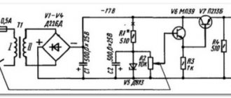
| Structure of a typical power supply |
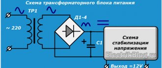
A computer power supply consists of several main components. A detailed diagram of the device is shown in the figure. When turned on, the AC mains voltage is supplied to the input filter [1], in which ripple and noise are smoothed out and suppressed. In cheap units, this filter is often simplified or absent altogether.
Next, the voltage goes to the mains voltage inverter [2]. An alternating current passes through the network, which changes potential 50 times per second, i.e. with a frequency of 50 Hz. The inverter increases this frequency to tens and sometimes hundreds of kilohertz, due to which the dimensions and weight of the main converting transformer are greatly reduced while maintaining useful power. To better understand this solution, imagine a large bucket that can carry 25 liters of water at a time, and a small bucket with a capacity of 1 liter, which can carry the same volume in the same time, but will have to carry the water 25 times faster.
The pulse transformer [3] converts the high voltage voltage from the inverter to low voltage. Thanks to the high conversion frequency, the power that can be transmitted through such a small component reaches 600–700 W. In expensive power supplies there are two or even three transformers.
Next to the main transformer there are usually one or two smaller ones, which serve to create a standby voltage that is present inside the power supply and on the motherboard whenever the power plug is connected to the power supply. This node, together with a special controller, is marked in the figure with the number [4].
The reduced voltage is supplied to fast rectifier diode assemblies mounted on a powerful radiator [5]. Diodes, capacitors and chokes smooth out and straighten high-frequency ripples, allowing you to get an almost constant voltage at the output, which goes further to the power connectors of the motherboard and peripheral devices.
| Typical PSU information sticker. The main task is to inform the user about the maximum permissible currents along the power lines, the maximum long-term and short-term powers, the final combined power that the power supply is capable of delivering | The design of modular power supply connectors can be very different. Their use allows disconnecting power cables that are not required in a separate system unit |
In inexpensive units, so-called group voltage stabilization is used. The main power choke [6] smooths out only the difference between the voltages +12 and +5 V. In a similar way, savings are achieved on the number of elements in the power supply, but this is done at the expense of reducing the quality of stabilization of individual voltages. If there is a large load on one of the channels, the voltage on it decreases. The correction circuit in the power supply, in turn, increases the voltage, trying to compensate for the shortfall, but at the same time the voltage on the second channel, which turns out to be lightly loaded, also increases. There is a kind of see-saw effect. Note that expensive power supplies have rectifier circuits and power chokes that are completely independent for each of the main lines.
In addition to power nodes, the block has additional ones - signal ones. This includes a fan speed control controller, often mounted on small daughter boards [7], and a voltage and current consumption control circuit implemented on an integrated circuit [9]. It also controls the operation of the protection system against short circuits, power overload, overvoltage or, conversely, too low voltage.
| Power supply shroud with installed 120mm fan. Often, special guide inserts are used to generate the required air flow |
Often, powerful power supplies are equipped with an active power factor correction. Older models of such units had compatibility problems with inexpensive uninterruptible power supplies. When such a device switched to batteries, the output voltage decreased, and the power factor corrector in the power supply intelligently switched to power supply mode from a 110 V network. The uninterruptible power supply controller considered this an overcurrent and obediently turned off. Many models of inexpensive UPSs with a power of up to 1000 W behaved this way. Modern power supplies are almost completely devoid of this “feature”.
Many power supplies provide the ability to disconnect unused connectors; for this, a board with power connectors is mounted on the inner end wall [8]. With the right design approach, such a unit does not affect the electrical characteristics of the power supply. But it also happens the other way around: poor-quality connectors can worsen contact, or incorrect connection leads to component failure.
To connect components to the power supply, several standard types of plugs are used: the largest of them - double-row - is used to power the motherboard. Previously, twenty-pin connectors were installed, but modern systems have a greater load capacity, and as a result, the new plug has 24 conductors, and often additional 4 contacts are disconnected from the main set. In addition to the load power channels, control signals (PS_ON#, PWR_OK), as well as additional lines (+5Vsb, -12V), are transmitted to the motherboard. Switching on is carried out only if there is zero voltage on the PS_ON# wire. Therefore, to start the unit without a motherboard, you need to close pin 16 (green wire) to any of the black wires (ground). A working power supply should work, and all voltages will immediately be set in accordance with the characteristics of the ATX standard. The PWR_OK signal is used to inform the motherboard about the normal functioning of the power supply stabilization circuits. Voltage +5Vsb is used to power USB devices and the chipset in Standby mode of PC operation, and -12 is used for the RS-232 serial ports on the board.
| This figure shows the pinout of power supply pins traditionally used in modern PCs |
The processor stabilizer on the motherboard is connected separately and uses a four- or eight-pin cable that supplies +12 V. Powerful video cards with a PCI-Express interface are powered via one 6-pin connector or two connectors for older models. There is also an 8-pin modification of this plug. Hard drives and drives with a SATA interface use their own type of contacts with voltages of +5, +12 and +3.3 V. For older devices of this kind and additional peripherals, there is a 4-pin power connector with voltages of +5 and +12 V (the so-called molex).
The main power consumption of all modern systems, starting with Socket 775, 754, 939 and newer, is on the +12 V line. Processors can load this channel with currents of up to 10–15 A, and video cards up to 20–25 A (especially during overclocking) . As a result, powerful gaming configurations with quad-core CPUs and multiple graphics adapters easily “eat up” 500–700 W. Motherboards with all controllers soldered to the RSV consume relatively little (up to 50 W), RAM is content with a power of up to 15–25 W for one stick. But hard drives, although they are not energy-intensive (up to 15 W), do require high-quality power. Sensitive head and spindle control circuits easily fail when the voltage exceeds +12 V or when there is strong pulsation.
| High-quality testing of modern power supplies can only be carried out at specialized stands. The photo shows the electronic filling of one of them. For thermal dissipation of large powers, a massive radiator is used, blown by high-speed fans |
The labels of power supplies often indicate the presence of several +12 V lines, designated as +12V1, +12V2, +12V3, etc. In fact, in the electrical and circuit structure of the unit, in the vast majority of power supplies they represent one channel divided into several virtual, with different current limits. This approach was applied to satisfy the safety standard EN-60950, which prohibits supplying power above 240 VA to contacts accessible to the user, since fires and other troubles may occur if a short circuit occurs. Simple mathematics: 240 VA / 12 V = 20 A. Therefore, modern units usually have several virtual channels with a current limit of each in the region of 18–20 A, however, the total load capacity of the +12 V line is not necessarily equal to the sum of the powers +12V1, +12V2 , +12V3 and is determined by the capabilities of the converter used in the design. All manufacturers' claims in advertising brochures, describing the enormous benefits of multiple +12 V channels, are nothing more than a clever marketing ploy for the uninitiated.
Many new power supplies are made using efficient designs, so they deliver more power while using small cooling radiators. An example is the widespread FSP Epsilon platform (FSPxxx-80GLY/GLN), on the basis of which power supplies from several manufacturers are built (OCZ GameXStream, FSP Optima/Everest/Epsilon).
Modern powerful video cards consume a large amount of energy, so they have long been connected with separate cables to the power supply, regardless of the motherboard. The newest models are equipped with six- and eight-pin plugs. Often the latter has a detachable part for easy connection to smaller video card power connectors.
We hope that after reviewing the main components of power supplies, it is already clear to readers: in recent years, the design of the power supply has become much more complex, it has undergone modernization and now requires a qualified approach and the availability of special equipment for full-fledged comprehensive testing. Despite the general improvement in the quality of blocks available to the average user, there are also frankly unsuccessful models. Therefore, when choosing a specific power supply unit for your computer, you need to focus on detailed reviews of these devices and carefully study each model before purchasing. After all, the safety of information, stability and durability of the PC components as a whole depend on the power supply.
Brief Glossary of Terms
Total power
– long-term power consumption by the load, permissible for the power supply without overheating and damage. Measured in watts (W, W).
Capacitor, electrolyte
– a device for storing electric field energy. In the power supply it is used to smooth out ripples and suppress interference in the power circuit.
Throttle
– a conductor rolled into a spiral, which has significant inductance with a low intrinsic capacitance and low active resistance. This element is capable of storing magnetic energy during the flow of electric current and releasing it into the circuit at moments of large current drops.
Semiconductor diode
- an electronic device that has different conductivity depending on the direction of current flow. Used to generate voltage of one polarity from alternating. Fast types of diodes (Schottky diodes) are often used for surge protection.
Transformer
- an element of two or more chokes wound on a single base, used to convert an alternating current system of one voltage into a current system of another voltage without significant power losses.
ATX
– an international standard that describes various requirements for electrical, weight, size and other characteristics of cases and power supplies.
Ripple
– pulses and short voltage surges on the power line. They arise due to the operation of voltage converters.
Power factor, KM (PF)
– the ratio of active power consumption from the electrical network and reactive power. The latter is always present when the load current in phase does not coincide with the network voltage or if the load is nonlinear.
Active CM correction circuit (APFC)
– a pulse converter in which the instantaneous current consumption is directly proportional to the instantaneous voltage in the network, that is, it has only a linear consumption pattern. This node isolates the nonlinear converter of the power supply itself from the power supply.
Passive CM correction circuit (PPFC)
– a high-power passive choke, which, thanks to inductance, smoothes out the current pulses consumed by the unit. In practice, the effectiveness of such a solution is quite low.