Step-by-step instructions for installing and installing pass-through switches
The given diagrams are quite simple to understand even for the untrained. But before you begin any action, you need to follow a number of rules:
- firstly, all actions must be carried out with the electricity turned off;
- secondly, it is necessary to use only high-quality tools.
Following these simple rules will help avoid injury and electric shock.
Tools you will need:
- Screwdrivers - one Phillips and one flat.
- To remove insulation from wires, use a knife, side cutters or a specialized tool for removing insulation.
- Indicator screwdriver.
- Pliers.
After the entire tool is assembled and the electricity is turned off, you can begin installation.
- First, the “feed” wire is laid into the distribution box from the switchboard. The wire is cut so that approximately 10–12 cm remains in the box. After that, the insulation is removed from it with a tool to a length of 1.5 cm.
- Secondly, one of the wires in the box, usually “zero”, must be connected to the wire coming from the lamp.
- Thirdly, the second wire from the lamp is connected to the common contact on the pass-through switch.
- Fourth, the remaining two pins are connected to the "input" pins on the crossover switch.
- Fifth, the “output” contacts of the crossover switch are connected to the second pass-through switch.
- The last remaining contact is connected to the “phase” of the supply wire.
When connecting wires in a junction box, it is not advisable to use twisting. Although this is the simplest connection method, it is also the most unreliable. Over time, with such a connection, gaps appear due to changes in temperature conditions in the room. In addition, it is prohibited by regulatory documents.
There are several recommended connection methods:
- crimping;
- welding;
- commissure;
- screw connections;
- self-clamping connections.
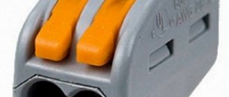
Of all the methods, the best and easiest is to use self-clamping connections. Since all other methods require a specialized tool and certain skills to work with it.
And when working with self-clamping connections, all that is required is to select the correct terminal blocks and their number. And to connect the wires, they need to be connected to the terminal block contacts, which is done quite simply. Another advantage of this connection is the ability to combine wires not only of different sections, but also made of different materials. Such terminal blocks are triple, with 4 or more contacts.
This article does not show all the wiring diagrams for a pass-through switch from three places. But in any case, they are all variations of the above schemes. In addition, there are several rules that you can follow to protect yourself when working with electric current. And also using modern technical solutions - terminals - you can speed up and simplify installation when connecting wires in a junction box.
To summarize this article, we can assume that by using variations of connecting pass-through and crossover switches from three places in everyday life, you can make your life a little more comfortable. In addition, having mastered the operating principle of each of them, you can create your own connection options. Although in most cases it will be enough to know only the above diagrams of pass-through switches from three places in order to correctly connect lighting sources to them.
connection diagram for a pass-through switch with 3 places
How does the device work and how is it different from a regular one?
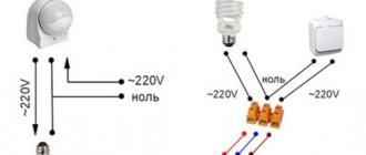
A pass-through switch is a device that is practically no different in appearance from a regular one. However, its purpose is somewhat broader. In addition to the classic switching on and off, the device switches circuits between each other using three fixed contacts.
This type of switches is usually used in pairs. The devices are connected in series and separate (split) the phase wires. At the moment of transferring contacts inside the pass-through device, one section of the electrical circuit is opened and another is closed.
In this case, the network connection diagram of this device is changed in such a way that any other switch in the circuit is ready to control the light sources. It is also possible to connect a pass-through switch and operate as usual, but then the meaning of all the elements of its design is lost.
Attention: Unlike a simple switch, a pass-through switch is more convenient in some cases, due to the additional switching function. It can be used either in pairs or alone, performing the role of a regular one. Pair activation significantly expands the functionality of devices, but is expensive
Since the phase wire is divided into two, the number of connections increases, and, consequently, the cables used
Paired activation significantly expands the functionality of devices, but is expensive. Since the phase wire is divided into two, the number of connections increases, and, consequently, the cables used.
The cost of such a network also increases due to the need to purchase a second switch. A simple device will cost less, but it will be much inferior to a pass-through device in terms of functionality.
Do-it-yourself pass-through switch (PV) 3-point connection diagram
The principle of a cross-disconnector A cross-switch is similar to a regular single-key switch, the only difference being the presence of four terminals inside. Having done this work once, there will be no problems understanding the process.
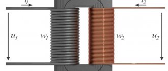
After a visual inspection, it is necessary to check and accurately determine which wires are phase and neutral. It is not an opening, but a phase switching to another line. They both contain inductive ballasts L1 and L2.
In order to install a cross switch you will need: Distribution boxes, their number depends on the area where you need to implement this lighting control system
An important rule is that the switch must always open a phase
How to connect a hob is written here, and how to install and turn on a water heater is written in this article. Using them together with cross switches, you can control lamps and lighting from several places. The first option has three contacts. When a signal is received, it closes the lighting circuit.
We recommend: Connecting a two-button switch
Therefore, today we will examine in detail the topic of how to connect a three-key switch. Another question is how complex such decisions are. If during the test it was discovered that the lamp was burning at full intensity, while lamps were burning in other places at the same time, then this place will be the phase break where the switch should be installed.
Main types of closing devices Switches, including triple switches, depending on the control method, come in keyboard and touch versions. But for the commercial sphere or production environment, solutions of this kind are in demand.
What is needed to complete the task
Now, when you press the middle key, the middle contact closes, and the phase with wire L2 enters the distribution box, where through point 3 and the ceiling wire it reaches the brown terminal of the HL2 lamp and the lamp lights up. If you think about it, everything is not so complicated, and the connection diagram for a pass-through switch from 2 points is generally simple. The phase is connected to the input of one of the pass-through switches with three inputs.
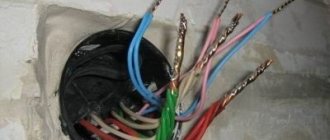
To avoid becoming a victim of an accident, you must adhere to the recommendations and rules of safe installation. Collecting wires in a box
In this case, it is important to find a common wire. That is, their operation is similar to the operation of a conventional double switch installed in the living room and designed to turn on the lamps of a large beautiful chandelier
The power is turned off at the distribution board of the apartment building. Connection of pass-through switches from THREE places
Cross Switch Connection
The crossover switch is installed simultaneously with the pass-through devices. All wire connections must go through the junction box. The crossover switch should act as a connecting element between the two pass-throughs. Two wires from each electrical appliance enter and then exit.
The wire must be routed from the junction box to the lamps and switch. A neutral wire is connected to the lighting fixtures. A phase is connected to the first pass-through switch. Next, paired wires connecting the switches are laid in the circuit. The wires from the last cross switch are connected to the lighting fixtures via a junction box.
In this way, you can create a lighting control circuit with the required number of positions. When using a switch at any point, the lighting devices connected to the circuit will be turned off and on.
Add. electrical services
- Electrical installation work in retro style
- Modern electrics in the Art Nouveau style
- Electrical design
- Electrolaboratory
- Insulation resistance measurement
- Electrician consultation
- Installation and replacement of an electric meter
- Installation of poles and power line supports
- Connecting an electric boiler to the network
- Electric heating at home
- Installing a voltage stabilizer
- Electric water heater installation
- Grounding a country house
- Lightning protection
- Modular-pin grounding
- Installation and laying of SIP cable
- Installation of cable wiring
- Connecting and extending electrical wiring
- Chasing walls for electrical wiring
- Checking the condition of the electrical wiring
- Do-it-yourself electrics
- Installation and operation of electrical equipment
- Replacing light bulbs...
- Supply of cable products
- Rules for electrical installations → PUE
Format of operation of the cross-switching device
The cross switch can only function in conjunction with two pass-through switches. This switching device performs the task of a line switch, that is, it alternately turns off one circuit and turns on another.
One lamp can be turned on and off from three places
Features of installation of non-standard switches
Installation of cross switching devices is carried out according to the following rules:
- the connection is made using wires with four or (in exceptional situations) two wires, which are well braided with insulating material;
- a switch with one or more keys is installed only if it is necessary to have a device capable of extinguishing the light at both the end and the beginning of a long room;
- The installation of the crossover switch begins at the moment when wires are laid around the house, of which there should be a lot, because the system requires connecting several contacts.
The last point is considered a disadvantage of the crossover switch: a large number of wires can cause a fire. But such a switching device has an undeniable advantage - a long service life, which is due to high wear resistance. Since the contacts of crossover switches close with a high frequency, which cannot be said about the connections of conventional or pass-through devices, their jumpers are made of a material that perfectly resists corrosion. Typically, alloy steel or copper is used as this raw material. Cross-switch jumpers must be covered with a protective sheath that does not allow condensation and dust to settle.
Electrical in residential premises
- Electrical installation in the apartment
- Electrician in a one-room apartment
- Electrician in a two-room apartment
- Electrician in a three-room apartment
- Electrician in a four-room apartment
- Electrical installation at the dacha
- Electrical installation in a private house
- Electrical installation in a country house
- Electrical installation in a wooden house
- Electrics in a house made of SIP panels
- Electrical installation in the garage
- Electrical installation in a cottage
- Electrical installation in a townhouse
- Electrics in baths and saunas
- Electrics in the cabin
- Electrician in a panel house
- Electrician in a log house
- Electrician in a stone and brick house
- Replacement of electrics in Khrushchevka
- Replacement of electrics in "Stalinka"
- Replacing electrical wiring in a panel house
- Temporary power supply
- Installation of hidden electrical wiring
- Hidden wiring in a wooden house
How to distinguish a crossover switch from a pass-through switch?
Quite often, when coming to an electrical equipment store with the desire to buy switches, some of which are pass-through, and some are crossover, and without receiving qualified help, our readers are faced with the problem of how to distinguish between a crossover switch and a pass-through switch?
Indeed, they are identical in appearance; moreover, a regular single-key switch looks exactly the same, so it’s very easy to make a mistake.
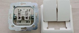
The main distinctive feature of the cross switch, which you need to pay attention to when purchasing, is related to its connection diagram - this is the number of connected wires and, accordingly, the terminals for them on the mechanism
Remember, a single-key crossover switch requires FOUR wires to operate, a pass-through switch requires THREE, and a regular switch requires TWO. In the case of two-key devices (and yes, two-key cross switches are also found), the number of connected wires is correspondingly doubled for each case.
Typically, on the back of the cross switch, next to the terminals for connecting the wires, the following symbols are marked:
In this case, the ABB Busch-Jaeger Basic55 series crossover switch is used as an example. As you can see, it has four spring clamps to connect the wires. In order not to make a mistake when connecting them, let's look at the cross-switch connection diagram.
The diagram also shows two pass-through switches; without them it is difficult to understand the principle of operation of the crossover switch, since it is usually used as at least the third switch in the circuit and is not used without two pass-through switches.
Now, I think, you understand the symbols printed on its back side, discussed at the beginning of the article. The two arrows pointing inside the intermediate switch (top two) show the terminals for the pair of conductors coming from the first pass-through switch
and the terminals with arrows pointing outwards are connected to the wires going to the second, final pass-through switch.
Accordingly, the connection of wires to the crossover switch must be done in exactly this order - two wires going from one pass-through switch in the circuit to one pair of terminals, and two other wires going to the second pass-through switch in the circuit to the second pair of terminals.
Thus, the intermediate switch has two main modes of operation.
First: When the signal going between the pass-through switches does not change. We can assume that the wires are continuous; this is equivalent to a circuit simply consisting of two pass-through switches. Conventionally it looks like this:
Second: When the signal is redirected, the wires going to the final pass-through switch are swapped with each other, in other words, they cross over with the conductors coming from the first pass-through switch. Conventionally it looks like this:
These images clearly illustrate the operation of the cross switch; now, I think it’s clear how it works and why it is called that.
Detailed step-by-step instructions for connecting and installing a crossover switch are described HERE.
So, let's summarize:
1. Having decided to make a system of switches at home in which the lighting is controlled from three or more places, it is necessary to include cross switches in the circuit, placing them between two pass-through switches.
If there are two cross switches in the system (and these are, respectively, four places for light control), then they are connected according to the same principle, in series: from the first pass-through switch there are two wires to the first cross switch, then two wires to the second cross switch, and then two from it to the final one to the passer.
The light control circuit, consisting of four switches, is shown in more detail in the image below.
3
The wires are connected to the cross switch in the following order: two wires from the first pass-through switch to the first pair of terminals, and two wires going further according to the scheme (no matter to the next cross-switch or to the last pass-through switch) are connected to the second pair of terminals
4. In order to distinguish a crossover switch from a pass-through switch when purchasing, you need to look at the connection diagram, usually indicated on the back side, as well as the number of wires and terminals connected to the device; the cross-over switch has FOUR, and the pass-through switch has THREE.
This is the basic information that you need to know in order to correctly connect a cross switch, the connection diagram of which turns out to be not so complicated if you understand the principle of its operation.
Related Posts
- What is a legrand pass-through switch, features of its connection diagram
- What is a switch for electricity
- Light switch diagram from two places
- Instructions for connecting a three-key switch with your own hands
- What letter and color indicate zero and phase in electrical engineering?
- Selecting and installing a two-key switch for open wiring
- How to install a socket
- Switch connection
- What could be the reason for the malfunction of the socket in one room, and why does it not work, but there is light?
- How to properly connect a light bulb to the mains via a switch
- Installation of a two-key switch legrand quteo
- Single-key switch connection diagram
- DIY touch switch rgb-light slider
- Repair of electrical equipment on ships - cable termination
- Cable current cross-section
- How to install sconces correctly: step-by-step instructions and installation tips
- Twisted pair or how to connect an Internet outlet: 7 stages of installation
- Connecting wires in a junction box: learning how to connect wires
- Wire cross-section for home wiring: how to calculate correctly
- How to replace an outlet in an apartment yourself
- What color is phase and zero in electrical engineering?
- Do-it-yourself repair of a single-lever bathtub faucet
- Options for AVR circuits for connecting a generator
- Terminals or twisting: comparing the pros and cons
- Overview of electrical wire connectors
Read with this
- What is a legrand pass-through switch, features of its connection diagram
- What is a switch for electricity
- Light switch diagram from two places
- Instructions for connecting a three-key switch with your own hands
- What letter and color indicate zero and phase in electrical engineering?
- Selecting and installing a two-key switch for open wiring
- How to install a socket
- Switch connection
- What could be the reason for the malfunction of the socket in one room, and why does it not work, but there is light?
- How to properly connect a light bulb to the mains via a switch
Analysis of the schematic diagram of the device contact groups
If you take the classic (single-key) design of the device, produced, for example, by ABB, and turn the back side towards the user, approximately the following picture will open.
There are 4 pairs of terminals on the base board, each of which is marked with corresponding symbols - in this case, “arrows”. With a technical designation of this kind, the manufacturer provides the user with information about the correct connection of the device.
This is what the terminal wiring of a device with a reversible locking function looks like. The differences from the design shown above are obvious. Based on these characteristics, the desired device configuration is usually selected.
The incoming “arrows” indicate the general (changeover) contact group. Outgoing “arrows” mark the permanent contact group.
Schematically, the interaction of groups looks like in the following figure:
The colored lines conventionally show how the contact groups are located inside the intermediate switching device. Each pair of operating terminals is marked with symbols indicating the input and output groups
The terminals of the common (changeover) group of the contactor receive conductors from the first pass-through switch involved in the electrical circuit. Accordingly, conductors come out from the terminals of the second (permanent) group of the contactor, which are connected to pass-through switch number two, also prudently included in the circuit.
This is a classic variation using two through and one reversible devices.
Scheme for introducing one crossover device into a circuit between two pass-through devices. Typically, this solution is typical for schematics used in domestic premises
The device, designed to act as a reversible switch, can actually be used in one of two modes of switching an electrical circuit:
- Direct switching is an analogue of two pass-through devices.
- Cross commutation is the main purpose.
The configuration of the first option is essentially represented by the functionality of a direct connection with the ability to connect or disconnect.
The second configuration method (by installing jumpers) switches the device to operating mode using an inversion switching scheme.
The reversing switch device supports configuration (by jumpers) for one of two possible mode functions. Thus, the cross-type switch acts as a kind of universal device
Don't miss: How to properly assemble an electrical panel with your own hands. Selecting wires for wiring in the panel
Thus, intermediate switches look functionally not just as switches for artificial light sources, but as switches of universal action. This factor expands the functionality of such devices and makes them convenient for use in different installation options.