Installation of branches in a socket box
The wiring can run inside the walls or on their surface.
The first option is simple to implement, but inferior in aesthetics. Hidden wiring provides for wall finishing after installation. However, when the need arises to repair the electrical network, the walls have to be destroyed. Connecting devices to the power cable must be safe and secure. Each outlet must have a housing to protect it from electric current. Mounted ones have their own box. To install built-in ones, socket boxes are used. They are made of dielectric materials, securely fix the device in the wall, prevent moisture from entering and are fireproof.
Grounding is installed in each socket box; there is enough space for laying wires. This method is considered reliable and guarantees protection. It is indispensable if additional installation of several sockets is necessary. Eliminates large-scale work. It is used for light loads in an apartment or house, under normal conditions.
Connection diagram for socket and switch: loop, series, parallel
Let's look at how to connect an outlet or a multi-unit unit. You can connect electrical outlets in parallel via a junction box or using terminals; this method is also called a daisy chain connection. When connecting electrical outlets with a cable, the cable is connected to the first unit of the block, and the cable for the next block is powered from the last. For a daisy chain connection, mandatory independent disconnections of the socket are required. To do this, the conductors are connected to the neutral conductors through terminals or soldering. Zero and phase are connected to the first electrical outlet. A clamp is placed on the grounding wire, from which a grounding wire is supplied to each of the units. To connect the second socket block, you need to connect the phase and working zero from the last unit of the first block, and the ground wire into the compressor.
Now let's look at connecting a conventional single-key switch. To do this, we connect the phase wire to the switch using a clamp marked with an English “L” or an “outward” arrow; we connect the zero to a clamp with an “inward” arrow or the letter “N”. We screw both wires securely. Since grounding is not used in switches, we cut off the excess wire and insulate it.
Another pressing question: “How to connect a switch from an outlet”? To do this, it is better to use a block consisting of an electrical outlet and one or more switches. A new cable is laid from the junction box. One core of the cable carries the phase to the switch, and the other leads the working “zero” to the socket. The remaining conductors pass to the lamps through switches. 3-wire wires (zero, ground and phase) are laid from the junction box to the lamps.
Basic connection options
In old houses, all connections were made in a junction box under the ceiling. After it, the wires diverged each to its consumer. With the advent of blocks - various devices assembled in a single housing - it became possible to save on cables and cut less wires. In addition, there is no need to carefully measure the height of the socket with the switch in order to place them exactly next to each other.
The disadvantage of such combined devices is that if one thing fails, everything will need to be replaced together. It cannot be replaced separately.
Single-key option
This is the simplest version of the block design. All you need is the unit itself and a connected 3-wire cable. In the distribution box itself, it is necessary to make the wiring: phase, zero - to the socket, zero - to the lamp, another wire from the lamp - to the switch. Now you need to make the necessary connections inside the block itself.
As can be seen from the figure, connecting elements in one block is no different from separate ones. A phase and a neutral go to the socket. The same phase goes to the contact of the switch, then to the lamp. Now everything is inserted into the box, screwed on, and the key is put on. If you did it right, everything will work.
If the outlet is grounded, then the cable will not have 3, but 4 wires. The fourth is yellow-green. It goes to the ground contact. You can't connect it anywhere else!
Two-key block
There are situations when you need to turn on the light in the bathroom or toilet, and then you need to connect the washing machine somewhere. An outlet can only be installed in the bathroom itself if it has the necessary waterproofing. If not, then it is best to mount everything in the hallway. To save space and wires, we will again use the “all in one case” block, but only now with two keys. Connecting it is also not difficult.
The first thing to do is to choose a suitable design. Remember that the washing machine uses a heating element - a tubular electric heater. When heating water like a household appliance, it can have a power of up to 2200 watts. The socket must have a rated current of 16 A (the power of the heating element itself, plus the machine motor, plus reserve). Grounding is required here.
Now let's move on to the connection itself. With this option, a cable with 5 cores will be lowered to the socket box from the distribution box. The phase end is red, or brown, or black. Zero – blue, light blue. Earth – yellow-blue
It is important not to confuse the markings so as not to get hurt later
Let's look at the diagram: the grounding (green in the figure) is connected to a special grounding contact of the socket. It is clearly visible: there are “antennae” on it, which get in the way when the outer cover is put on.
The phase end (red) goes to one of the terminals. From there, jumper to the switch. From its output contacts, two wires go (yellow and beige in the figure) to the junction box, and from there to the corresponding lamps. If you need to change the order in which the keys are turned on, swap the yellow and beige ends on the terminals.
Block with three keys
Don't think that the three keys are not used anywhere. This can be convenient when, in addition to the bathroom and bathroom, there is a kitchen nearby, and the lighting is turned on from one wall. This is especially common for small apartments. But you can turn on decorative lighting, depending on your imagination.
So, we have a socket and a three-key switch in one housing. A cable with 5 or 6 cores comes from the distribution box (with or without grounding). For simplicity, let's consider an example without grounding. The circuit differs from the two-key design only in the presence of one more contact, and as a result, a connection.
The same picture is visible as in the two-key circuit. The phase wire goes to the socket, and a jumper comes from it. Zero - only to the socket. And three wires go out - for three lamps, or for three groups of lamps. The more cores a cable and connections have, the easier it is to make a mistake. Therefore, you need to be careful during installation. If something doesn’t work out, it’s better to rest a little and then carefully check everything again.
Electrical outlet device
Almost any master had to deal with connecting an outlet. At first glance, this procedure is very simple, but there are many nuances hidden beneath it. To prevent a self-connected outlet from becoming a source of problems, you need to understand the principle of its operation. It consists of the following components:
- Decorative overlay with fixed screw.
- Socket box. To fasten the element inside the mounting hole, it has tabs, with the help of which the insert is attached to the hole. The pads, whose contacts are movable, are more difficult to install, but thanks to their design it is possible to adjust the position in tilt and height. It is advisable to choose models with two-toothed feet. Compared to single-tooth ones, they are much more reliable.
- Contact box assembled. The terminals can be connected in various ways, such as with contact screws directly, or they can be made as a single unit. Two contacts, neutral and phase, as well as grounding which is located separately.
Connecting an internal Internet outlet
The main task of the connection is to be able to correctly disassemble the Internet outlet, since each manufacturer solves this problem in its own way.
The most important thing is to disassemble it so that there is free access to the contacts with the microknives. It is in this part that the connection is made, after which the housing cover with contacts is closed. Each model of such an outlet has its own method of assembly and disassembly.
If we take, for example, a Legrand computer socket, then in order to get to the place where the wires of the Legrand Valena RJ-45 socket are connected, you first need to remove the front cover. Inside the case you can see a white plastic panel with an impeller, where an arrow is drawn (see photo).
The handle on the panel is turned in the direction of the arrow, after which the front panel is removed. On the surface of the panel there is a metal plate with a pattern, from which you can determine which contacts and which wire should be connected. The color marking of twisted pairs is also indicated here. Before starting the connection, wires prepared for the connection process are threaded into the hole located on the plate.
To make it more clear, it is better to watch the prepared video.
You can also find a socket for connecting the Internet from Lezard. Here the design is completely different. The front panel is designed with screws, so to remove it, just unscrew these screws. As for its insides, everything here is secured with latches. To remove the insides from the body, you need to pick up a regular, small screwdriver and squeeze the clamps.
To get to the contact group and remove it from the housing, you need to press the latch, which can be found on top. As a result of such actions, you may end up with a box in your hands, from which you will have to remove the cover to get to the contacts. To remove the cover, just pry the side petals with a thin object. You still have to put in some effort, since the latch is quite elastic. At the same time, you need to remember that you are holding plastic in your hands and if you do not do everything carefully, you can break it.
For greater clarity, we suggest you watch the video tutorial.
In conclusion, it is worth noting that the presence of a corresponding video on the Internet simplifies the process of mastering various actions or carrying out work related to connecting computer sockets. Despite the fact that each outlet model is designed differently, the connection process is the same for all. The most important thing is to master the connection process yourself, associated with certain features. It would seem that it would be easier if the connection was made using twisting or soldering, which would be accessible to almost everyone. But at the same time, it would not be possible to ensure the compactness and accuracy of the connection itself. But such connections have their advantages: you wouldn’t have to stock up on jacks. Although, on the other hand, this connection method is more designed for professionalism, simplicity and speed, especially if you use a special tool.
And, nevertheless, if you have at least some skills in working with electrical wires, then such a connection does not contain any difficulties. Without inviting any specialists, you can actually install a computer network in your apartment or private house. Moreover, such specialists will charge a considerable amount for this.
The activity is quite safe if you follow basic rules. Moreover, this is a simple procedure that takes no more than 15 minutes, when there is already a socket for installation, with a fixed socket.
Types of devices and their features
There are quite a lot of varieties of plug sockets and blocks. Each type has its own design features and purpose.
- Hidden devices are mounted directly into the wall - in special socket boxes.
- Open devices are produced for those apartments where the electrical wiring is not hidden in the wall.
- Retractable socket blocks are mounted in a table or other furniture. Their convenience lies in the fact that after use, the devices can be easily hidden from prying eyes and playful children’s hands.
The devices differ in the method of clamping the contacts. It comes in screw and spring types. In the first case, the conductor is fixed with a screw, in the second - with a spring. The latter are more reliable, but they are not so easy to find on sale. The devices are fixed to the walls in three ways - claws with jagged edges, self-tapping screws or a special plate - a support that facilitates both installation and dismantling of the socket.
In addition to conventional, inexpensive devices, there are models equipped with grounding contacts. These petals are located in the upper and lower parts, and a grounding wire is attached to them. To ensure safety, sockets are equipped with curtains or protective covers.
Main popular types
These include:
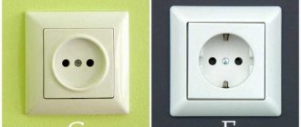
- type “C”, it has 2 contacts - phase and zero, usually purchased if intended for low or medium power equipment;
- type “F”, in addition to the traditional pair, is equipped with one more contact - a grounding one; these sockets are becoming more popular, since a grounding loop has become the norm for apartments in new buildings;
- Type “E”, which differs from the previous one only in the shape of the grounding contact, is a pin, the same as the elements of the socket plug.
The last type is less common than the others, since it is less convenient to use: turning the plug 180° with such a socket is impossible.
The security of the case is the next difference between the models. The degree of security is indicated by the IP index and a two-digit number following these letters. The first number indicates the class of protection against dust and solids, the second - against moisture.
- For ordinary living rooms, IP22 or IP33 class models are sufficient.
- It is recommended to buy IP43 for children, as these sockets are equipped with covers/curtains that block the sockets when the equipment is not in use.
- IP44 is the minimum required for bathrooms, kitchens, and baths. Not only strong humidity, but also splashes of water can pose a threat. They are suitable for installation in basements without heating.
Installing an outlet on an open balcony is a sufficient reason to purchase a product with a higher degree of protection, this is at least IP55.
Features of installation of daisy chain connection
As already noted, the daisy chain method is used to connect sockets located in the same group, which power low-power devices, such as a computer, audio equipment...
This type of connection is more economical and technically simpler. After all, to implement it there is no need to lay a lot of cables and use additional protection. But it is worth noting that each additional point of the created chain will make it more vulnerable.
For example, we know that the rated current per outlet should not exceed 16A. If you connect such a load to one point, then nothing bad will happen. But when you turn on such a load on at least 2-3 sockets of one line, its total readings will increase, and as a result, the power cable may not withstand it.
According to the PUE, during a daisy chain connection, it is not allowed to break the PE conductor of the protective grounding wire. In any case, its contour must remain unbroken.
The use of one of the technical solutions helps to reduce material costs when connecting PE conductors to sockets:
Installation using connectors
This type of connection is chosen when it is necessary to connect sockets that are located almost close to each other.
With a daisy-chain connection, the main wire supplied from the power panel goes to the seat of the multi-place socket box. From it it powers the first socket, from which, through its own contacts, power goes to the second socket, from the second to the third.
When installing with a cable, the incoming and outgoing cables are connected directly to the contact part of the device. For this reason, craftsmen recommend using models equipped with a flat spring contact.
As a last resort, samples whose contacts are made in the form of a plate pressed with a bolt are suitable. Devices in which the role of a contact is played by an ordinary bolt are not at all suitable for this purpose.
One of the mandatory operational requirements when connecting sockets with a cable is the need to reduce the contact resistance in the circuit between the contact terminals of the socket and the contacts of the electrical plug.
To achieve the desired effect, the terminals are shaped to increase the area of the contacts themselves, as well as the force of their compression. Today, Scotchlok connectors are often used to install protective zeros. This type of clip connector is equipped with mortise contacts.
To use a clip connector, you should choose products that provide additional space to accommodate it.
Through the contact of the first socket, the phase wire of the power cable and the PE conductor of the loop are supplied, which goes further to the second socket. On the second contact there are neutral wires of the power cable and a cable to the second socket. The same principle is used to connect to the third and subsequent outlet, if its presence was provided for in the power wiring diagram.
According to the PUE clause 1.7.144, in order to connect the open conductive part of the device to the neutral or grounding conductor, it is necessary to make a branch in the cavity of the casings of electrical installation products intended for this purpose. These include sockets.
The main task when connecting sockets equipped with grounding is to ensure a reliable connection of elements along the entire line. After all, if for any reason the grounding contact burns out in the main power socket, all other participants in the circuit will lose the protective zero. Therefore, if it is necessary to branch the grounding conductor, the most reliable type of connection is used - crimping.
The method involves, in addition to the use of conventional twisting of wires, additional insulation and crimping of their ends using a sleeve. This ensures uninterrupted contact of the chain elements and its high mechanical strength.
Installing an additional junction box
This method involves installing a branch box or connecting block connected to the shield next to the socket cable. In this case, the cable is branched in the distribution box in the area before being connected to the socket box.
The connections inside the branch box leading to each outlet are most often made by welding. It is recommended that the insulated ends of all conductors be laid in junction boxes so that they do not intersect or touch each other.
Problems on parallel connection of conductors with solutions
Formulas used in the lessons “Problems on parallel connection of conductors”
Problem No. 1. Two conductors with a resistance of 200 Ohms and 300 Ohms are connected in parallel. Determine the total resistance of the circuit section.
Problem No. 2. Two resistors are connected in parallel. The current in the first resistor is 0.5 A, in the second - 1 A. The resistance of the first resistor is 18 Ohms. Determine the current strength throughout the entire circuit and the resistance of the second resistor.
Problem No. 3. Two lamps are connected in parallel. The voltage on the first lamp is 220 V, the current in it is 0.5 A. The current in the circuit is 2.6 A. Determine the current in the second lamp and the resistance of each lamp.
Task No. 4. Determine the readings of the ammeter and voltmeter if a current of 0.1 A flows through a conductor with resistance R1. Neglect the resistance of the ammeter and supply wires. Assume that the resistance of the voltmeter is much greater than the resistance of the conductors under consideration.
Problem No. 5. Three electric lamps are connected in parallel in the battery circuit. Draw a circuit for turning on two switches so that one controls two lamps at the same time, and the other controls one third lamp.
Answer:
Problem No. 6. The lamps and ammeter are turned on as shown in the figure. How many times do the ammeter readings differ between open and closed switches? The lamp resistances are the same. The voltage is maintained constant.
Problem No. 7. The voltage in the network is 120 V. The resistance of each of the two electric lamps connected to this network is 240 Ohms. Determine the current in each lamp when they are connected in series and in parallel.
Problem No. 8. Two electric lamps are connected in parallel at a voltage of 220 V. Determine the current strength in each lamp and in the supply circuit if the resistance of one lamp is 1000 Ohms and the other is 488 Ohms.
Problem No. 9. Two identical lamps are connected to the circuit. When the rheostat slider is positioned at point B, ammeter A1 shows a current of 0.4 A. What do ammeters A and A2 show? Will the ammeter readings change when the slider moves to point A?
Problem No. 10. OGE Two series-connected resistors were connected to a network with a voltage of U = 24 V. In this case, the current strength was I1 = 0.6 A. When the resistors were connected in parallel, the total current strength became equal to I2 = 3.2 A. Determine the resistance of the resistors.
Problem No. 11. Unified State Examination A milliammeter, designed to measure currents up to IA = 25 mA, having an internal resistance of RA = 10 Ohms, must be used as an ammeter to measure currents up to I = 5 A. What resistance should the shunt have?
This is a summary on the topic “Tasks on Parallel Connection of Conductors.” Choose what to do next:
- Go to topic: PROBLEMS on the work of electric current
- View the summary on the topic Connecting conductors
- Return to the list of Physics notes.
- Test your knowledge of Physics.
How to properly connect an outlet - detailed instructions
For single and double sockets this is not difficult to do (installing such sockets involves drilling one hole in the wall), but installing a triple socket will be more difficult. It is necessary to accurately mark the centers of the sockets, taking into account the distance between them.
If it is necessary to lay wiring in a new location, straight lines (horizontal and vertical) are drawn on the wall. Curvilinear and oblique routes are not allowed: this will make it difficult to find the location of damage and repair the wiring in the future.
Required tools and materials
To work in a house with brick and concrete walls, you must have at your disposal:
- perforator;
- a special attachment – a crown with a diameter of 70 mm with carbide cutters;
- voltage indicator;
- chisel;
- hammer;
- straight and figured screwdriver;
- narrow and medium spatulas.
To carry out electrical wiring, it is necessary to replace the old aluminum cable with a new copper cable. The core insulation is double, the cross-section (for the socket group) is 2.5 mm². It is recommended to use cable type GDP-2×2.5 or GDP-3×2.5. In addition, you will need socket boxes (plastic cups with a diameter of 67 mm), alabaster for fixing them and sockets. The latter are chosen according to personal preferences and the color of the front panel: it can be combined with the color of the finishing material for the walls.
Wall chipping
In order not to make wide grooves and avoid cleaning up large amounts of construction waste, you can use the following method when grating walls.
It is convenient for laying single cables, which most often has to be done when installing sockets. It is necessary to use a grinder to make a cut of the required depth. In this case, during the cutting process, the “diamond” wheel should be given wave-like movements: this will slightly widen the groove. In the places where the cut turns (that is, in the corners), widen the groove with a chisel and hammer.
A flat three- or two-core cable of the GDP type fits well into a groove made in this way due to its flat cross-section. At the same time, there is practically no need to “freeze” it with alabaster solution: the cable will stick well to the wall. After laying it, the wall is leveled with gypsum mortar using a medium-width spatula.
Before starting electrical installation work, use the switch located in the switchboard to turn off the power supply. You need to check for voltage at the terminals.
How to connect a grounded outlet
To avoid problems, you must first make the correct wiring connections in the installation box.
It should be remembered that the phase wire (usually the insulation color is brown, black or red) must be connected to the twisted phase wires. It is determined by a voltage indicator. Neutral wire (blue, white) - with neutral, “ground” (yellow, yellow-green) - with grounded wire. Now about how to connect a grounded outlet. An error can be life-threatening: connecting the phase wire to the ground terminal will lead to voltage appearing on the body of the household appliance. To avoid this, you need to know the location of the socket terminals. "Ground" is connected to the central terminal. The remaining two terminals have a phase wire and a neutral wire (they can be swapped).
Grounding is necessary for safety: it will prevent electric shock to a person if current leaks into the housing of household appliances. Therefore, the “ground” core of the cable connected to the socket must be connected at the other end to the “ground” cores of the cables laid from the switchboard at the entrance.
How to connect a double socket
There are no special differences in the installation of such an outlet, since it will also have three terminals, like a single one. The only difference is the orientation of the housing and the plug holes. Those installed vertically may differ in appearance from those installed horizontally. The installation method does not affect anything and is chosen based on personal wishes.
The socket is fixed in the socket box, “frozen” using alabaster (applied with a spatula), and then its front panel is installed.
«>
Not yet!
Where are double sockets installed?
Their metal may damage the insulation when tightening the screws.
Removing an old outlet Before you start working with electrical wiring, you need to take care of your safety. Where are double sockets installed?
Instructions for those who want to connect the outlet themselves: If the quality of the installation is in doubt, seek help from a professional electrician. But since the socket box, the lever on which is located in the center, is subject to a double load, after prolonged use the fastenings become loose and weaken. When the caliper frame is securely fastened, a decorative trim is installed. Before connecting a double socket, you need to make sure that the power supply is turned off and there is no voltage on the cable. Like power sockets, Internet analogues are inserted into sockets. The distribution cable is laid openly or closed in the walls. Finally, its caliper is connected with self-tapping screws to the body of the installation box.
Connecting an outlet to a three-wire electrical network has a slight difference. If you do not do this, then you will not be able to install and connect the working part. It is better to check the operation of the outlet when turning on inexpensive household appliances, for example, a table lamp.
The wiring looks a little different, with a unique connection. There are also models that are not equipped with fixing tabs, which are secured by screwing them onto screws.
Therefore, when installing electrical wiring, you should clearly understand what can happen if you do something wrong. To make it easier to solve the problem, the wire insulation is painted in different colors: phase - red, brown or white; zero - blue, blue or black; grounding - yellow or green. To plug an electrical appliance into an outlet, you have to turn them over. By pressing the fasteners, the upper part of the device is separated from the caliper. In addition, on the front part there are mounting screws for fixing the socket support.
Deviation from this pointer may result in uneven installation of the decorative socket cover. For ease of subsequent connection, it is recommended to slightly raise or lower the ends of the wire. The lack of power in the network is checked again. How to connect a Socket and Switch (EASY)
Mixed connection and grounding in series connection
If you decide to use a series connection of sockets, you can strengthen the overall design by using a mixed method. The essence of the method is as follows:
- A central cable is connected to the distribution box from the common panel board.
- In the preliminary wiring plan, the most distant point of access to power is selected.
- The selected outlet is connected from the distribution box cable.
- The rest are powered from this device.
This method increases the reliability of the network. If an outlet fails, the others continue to work. Disabling the entire system is possible only in the event of a malfunction of the main cable, twisted in the junction box.
Grounding is a must. With a serial connection, if a wire burns out at one point, the rest are left without protection. The optimal way to connect sockets to each other for grounding is mixed. The main cable is fixed under the ceiling, then branches are made for each access point.
This technique has disadvantages - the large length of the wires used, the need to install several junction boxes (for each branch). To know for sure whether high-power devices can be connected to the network, it is necessary to calculate the voltage before the cable wiring stage. An accurate calculation will help you choose how to connect the sockets in the end - in series, parallel or mixed.
Combined method
In some cases, it is necessary to simultaneously increase the capacity and voltage of the battery. For this, two combined connection methods are used:
- First, several batteries are connected in series. In this way, the required operating voltage is achieved. At the second stage, parallel switching of several batteries obtained by connecting batteries in series is carried out. Several series circuits are created to achieve the required capacity.
- The second method involves parallel switching batteries with the required capacity, after which they are connected in series to achieve the required current.
The combined method is used extremely rarely, as it involves the use of several power sources
When choosing the most suitable batteries, attention is paid to their technical condition, capacity and voltage of the generated current.
Power connection procedure
To properly assemble the socket and connect, follow the following instructions:
- All work must begin with de-energizing the power line. To do this, turn off the circuit breaker in the distribution panel to the desired line if the installation is carried out on an existing wire.
- Using a test lamp or multimeter, we make sure that there is no voltage on the wire that will be connected.
- Stripping the wire. The cable laid to connect the socket, and which has already been routed through the socket box, needs to be prepared for connection. To do this, remove the wire insulation at a distance of 12-15 centimeters, trying not to damage the main insulation of the cores.
- To connect the outlet itself, we connect the bare wires to the contacts. For better contact, we twist 4-6 millimeters of the core into a ring and put it on the clamping screw of the terminal.
- The socket is installed in the mounting hole after all wires are connected. Distortions are unacceptable. The wires must be carefully laid deep into the socket box and secured with clamping paws.
- Install the cover.
Basic rules for wiring sockets
The rules for installing sockets and the tools that may be needed in the process are regulated by SNiP (building codes and regulations) and GOST.
When installing electrical wiring and working with sockets, you must familiarize yourself with the Electrical Installation Rules (RUE):
- wiring elements (distribution box, meter, sockets, switches) must be easily accessible;
- sockets are installed at a distance of 50-80 centimeters from the floor. The rule is taken for safety purposes when the premises are flooded;
- if there are gas or electric stoves in the room, as well as heating radiators and pipes, sockets are installed at a distance of 50 centimeters or more from grounded equipment;
- wires to devices are laid from bottom to top;
- sockets in the room are installed at a rate of no more than 1 per 6 square meters. You can connect more sockets only in the kitchen;
- equipment cannot be installed in the toilet;
- The wiring is laid at a distance of 10-15 centimeters from pipes, floor beams and ceilings. The height of the wiring from the floor should be 15-20 cm;
- wiring and connection of wires are carried out inside the distribution box;
- “Ground” and “Zero” are connected to the devices with a bolted connection.
This is all the information you may need when connecting a double socket yourself. Having mastered the necessary rules, anyone can connect a new device with their own hands.
Experts recommend that beginners pay special attention to following safety rules, since they will have to work with contacts that conduct current.
You can once again familiarize yourself with the features of the double socket installation process by watching the video:
How to properly connect an outlet
Not every home craftsman, even if he has some experience in performing repair work, knows how to connect the outlet correctly to avoid problems such as short circuits or power overloads.
On the one hand, such work does not take much time and does not require a large amount of specialized knowledge, on the other hand, failure to comply with the basic rules and installation features can lead to a fire hazard. Moreover, in a modern apartment and private house quite powerful equipment can be installed (from an electric kettle to an electric boiler).
Increasing loads lead to the need to choose the right outlet and decide on its connection diagram (if necessary, providing grounding).
Components for assembling a triple socket
Let's look at what main components our triple socket will consist of. The modern electrical equipment market offers customers a wide range of sockets. However, in this abundance, finding a triple socket in a single housing is very problematic. Even after finding the product you are looking for, a person may encounter two problems:
- 1. Obviously overpriced product;
- 2. The model does not meet the buyer's requirements.
What to do in such a situation? Most craftsmen use this method in 99% of cases - they assemble a block of single sockets
. Therefore, a triple socket is often assembled from three ordinary sockets.
To do this, we need three regular sockets with a rated current of 16 A. Moreover, we only need their internal part. You can safely throw away the overhead frames for each outlet, since we won’t need them. And to combine three single sockets, we need a special overhead frame with three holes, which will create the appearance of a single whole.
Compliance with safety precautions when installing sockets
Work with electricity is classified as dangerous. Even low voltage leads to burns, injuries and other unpleasant consequences. Compliance with safety precautions:
- de-energize the room in which the work is being carried out;
- check the area before starting with a special device (you can plug the device into the network);
- use rubber gloves and equipment with rubberized handles;
- when “increasing” the length, it is not enough to twist the wires; soldering is required;
- contact with connected bare cables is not allowed;
- the excess should not “stick out” - it is shortened and placed in the wall;
- check whether the devices are suitable for the current and voltage levels used.
Open and closed wiring
The difference between the methods is noticeable to the naked eye. The closed wiring is located inside the wall, for which grooves (grooves) are punched or cut into it, in which the connecting wire is hidden under a layer of putty. Open wiring is laid along the surface of the wall, on which it is held in special fasteners or laid in plastic guides - cable channels.
Accordingly, if you can see the wires that fit into the outlet, then the wiring is of an open type. Otherwise, closed wiring is used, for the installation of which the walls were cut.
These two methods of connecting an outlet can be combined with each other - if the old points are connected in a closed way, then nothing prevents you from connecting a new one in an open way. There is only one choice - in wooden houses the socket can be connected exclusively in an open way, just like all other electrical wiring.
Open wiring - advantages and disadvantages
An analogy with the most common extension cord (surge protector), which is essentially an additional branch of the electrical network, but is connected not to a junction box, but to an outlet, will help you understand why open wiring is good.
Advantages:
- You don't have to cut the wall to install a new outlet. This is especially true for those premises that have already been renovated.
- Installation does not require tools such as a wall chaser or a hammer drill.
- In the event of a breakdown, you don’t have to open the wall - all the wiring is in front of your eyes.
- Installation speed. Even after all the work has been completed, adding another point to the existing wiring is a matter of several minutes.
- If desired, you can quickly completely change the wiring - ideal for temporary connection schemes.
Flaws:
- There is a high probability of external influence on the wiring - children, pets, you can simply accidentally hook it. This disadvantage is mitigated by laying wires in cable channels.
- Exposed wires spoil the entire interior of the room. True, it all depends on the design abilities of the owner of the room - cable channels will fit perfectly into modern design solutions, and if the room is made in a retro style, then special wires and other accessories are produced for this.
- The need to purchase special fasteners, even if cable ducts are not used - in wooden houses, open wiring should be laid at a distance of 0.5-1 cm from the wall surface. Wires are often laid inside iron pipes - all these requirements are aimed at increasing the safety of using open electrical wiring.
As a result, this connection method justifies itself if for some reason there is no point in laying the wires to the outlet inside the wall. Besides the fact that the wiring will be visible, there will be no differences in the operation of the outlet.
Hidden wiring - pros and cons
Despite some significant disadvantages, it is used almost everywhere - the advantages of its use still outweigh.
Advantages:
- The wires to the socket fit into the wall, so wallpaper or other finishing can be done freely on the outside.
- Meets all fire safety requirements (in concrete buildings) - even if a short circuit occurs, there is no fear of a fire from the wires in the wall.
- There is a very low probability of damage to the wiring - it can only be damaged when drilling walls.
Flaws:
- For installation you need to cut the walls.
- It is difficult to carry out repair work.
- If the walls are finished, then after installing an additional outlet you will have to redo it.
The disadvantages are leveled out by preliminary calculations - if you plan in advance where and which block of sockets should be installed, then problems usually do not arise in the future.
Advantages and disadvantages
The final version of the wiring diagram
To determine the optimal connection diagram for sockets and switches, it is necessary to prepare a wiring plan, calculate the number of devices and the possible maximum power. At the same time, in newly built buildings it is necessary to plan future possibilities without unnecessary modesty: an additional TV, the purchase of a separate freezer, and the like.
Based on the data received, the connection type is selected. The advantages of the sequential method include:
- simple connection system and circuit assembly;
- the ability to adjust the voltage level, make it less;
- You can use one fuse per circuit.
Conclusions and useful video on the topic
Video guide on using the loop method:
Video: one of the safe options for connecting sockets:
Given that the amount of electricity spent on household needs is only increasing every year, and therefore the requirements for the reliability of sockets will certainly increase, a parallel wiring diagram should still be preferred. Especially when it comes to serious energy consumers. To power lamps, electric alarm clocks and similar devices, a cable connection option is suitable.
Connection methods
Ways to connect sockets
Before connecting many power outlets in a row, it is important to understand the existing methods of connecting them. Depending on the order of switching of individual conductors, the following options are distinguished:
- Parallel connection, in which the sockets must be connected in a star.
- A serial connection, otherwise called a “loop”.
- Combined connection using a loop and a star.
- Ring connection.
Each of the listed methods is selected depending on the architecture of the room and considerations of saving on installation products. A parallel star connection is convenient when distributing the power supply network from a single center (distribution board, for example).
The sequential method (or loop) is used when a whole series of sockets installed one after another is turned on on a given line. The individual contacts (phase and neutral) are connected to each other in parallel; the method is called serial only because of the order in which the socket nodes are located.
When combined, in separate areas, the products are installed in a row, after which a “star” is built from one of them.