How to draw up a grounding inspection report
As you might guess, the safety of workers depends on the serviceability of the grounding conductors.
If the device malfunctions, there is a risk of electric shock. When working properly, the ground electrode will conduct current through itself for a certain time. This will prevent a dangerous situation. Accordingly, it is extremely important that grounding devices are in good working order. That is why their inspection is carried out by specialized companies that provide qualified specialists. Naturally, such companies have a license that allows them to carry out such activities. The frequency of such inspections is once every six years. But this applies to thorough checks using special devices. As for visual inspection, visible parts of the grounding should be visually inspected every six months. However, you need to understand that if there is a suspicion of a malfunction, a thorough check can be carried out earlier.
Separately, grounding is checked only in isolated cases, for example, when a malfunction is detected. It is usually checked in conjunction with electrical equipment testing. As you might guess, the purpose of such a test is to determine the quality of the grounding.
It cannot be said that the EL-8 form is strictly mandatory to fill out. However, practice shows that some inspection authorities do not recognize a document as valid if it is drawn up in free form. Thus, experts recommend using this form.
( Video : “Grounding 2 meters? Checking. Grounding circuit 2 and 3 meters, measured.”)
When filling out, you must ensure that there are no errors. Even a minor typo can cause significant distortion of information. If one was discovered after filling out, it is better to start drawing up a new document. This way you can avoid unnecessary questions from inspection authorities.
Contents of the act
At the top of the act, information about the organization on whose balance sheet the equipment subject to inspection is located is indicated. In essence, this party performs the function of a customer. Information about the performing company is also written here. The number of the registration certificate and information about the license are indicated. Below is the title of the document, which reflects the essence of its preparation. Then you can start filling out the main part:
- climatic conditions under which the test took place;
- the purpose of this event;
- it is necessary to mention the documents that the verification results must correspond to;
- type of electrical equipment whose grounding is checked.
Since the grounding system involves the use of soil, its characteristics need to be described in detail. For example, the resistivity of the soil, its nature and type are indicated. Below is a table that is intended to display the results of the research.
The following columns are present here:
- serial number;
- purpose of the grounding device;
- the grounding point at which the test was carried out;
- distance to potential and current electrodes;
- grounding resistance;
- seasonal coefficient;
- conclusion.
In the column intended for conclusion, the responsible persons indicate whether the resistance meets the existing standards or not. Next is another table in which you need to indicate which instruments and special devices were used in research work.
The following information is provided here:
- serial number;
- type of device;
- factory number;
- characteristics of the device;
- dates of inspections of these devices;
- device verification certificate number;
- name of the organization that issued this certificate.
At the bottom of the document there is a “Conclusion” item. If the resistance of the grounding electrode meets the standards, this should be written about. If inconsistencies are found, this should also be reflected in the document. Also in the final part, the specialists who performed the inspection are indicated. Their positions are noted and autographs with transcripts are given. Information about the manager who checked this act is also indicated. Here he also signs and deciphers it. With his autograph, the manager confirms that the correctness of the document has been verified.
It is logical to assume that this protocol specifically concerns the grounding devices being tested. No corrections can be made during compilation. If mistakes are made, experts recommend starting to fill out a new document.
Briefly about inspections
According to PTEEP, the frequency of inspections of grounding loops (grounding devices) should be once every 6 years. A visual inspection of visible parts of the device should be carried out once every six months. Checks can be carried out more often, especially if there is a suspicion of a malfunction of the grounding equipment.
Ground resistance testing is usually carried out in conjunction with other tests. Its task is to evaluate the protective properties of electrical equipment.
The inspection can be carried out by special organizations that have permits for such work, are certified by the Ministry of Energy, and have special laboratories and instruments for carrying out measurements. Employees must undergo appropriate training, occupational safety knowledge testing, and a medical examination.
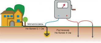
For your information! A grounding device (grounding loop) is necessary to protect workers from electric shock due to breakdown of electrical equipment.
If the system is operating, current will flow through the ground electrode for a short period of time. And a dangerous situation will not happen at the enterprise. Therefore, it is important to monitor the condition of grounding devices.
Program and methodology for testing power cable lines up to 10 kV, page 5
5.3.7 Measuring the insulation resistance of cables to which voltage may be applied from the opposite end is permitted only if a written or telegraphic (telephone) message has been received from the person in charge of the installation of the line supplying the other end about the disconnection of the line disconnector, the disconnection of the circuit breaker and grounding of lines.
5.3.8 When preparing for measurements, the megohmmeter and connecting wires are checked. For this:
— the megohmmeter is installed horizontally on a dielectric mat;
— connecting wires are connected to a megohmmeter;
— the free ends of the connecting wires are short-circuited;
- measure the resistance value. The device should show zero resistance;
- unclench the ends of the connecting conductors;
- measure the resistance value. The device should show a resistance equal to infinity.
5.3.9 Before starting measurements with a megohmmeter, you must make sure that there are no people working on the cable and warn people near the cable about the start of measurements. The person conducting the measurement must position himself in such a way that any accidental contact, either by the worker himself or by the wires of the device, with live parts of the switchgear is excluded.
5.3.10 Before each measurement of insulation resistance, the cable must be discharged to ground. This operation is performed at the end of the cable where the measurements are being made, and only after checking that there is no voltage. The person carrying out the discharge must wear gloves and galoshes.
5.3.11 When measuring the insulation resistance of cable cores, a megohmmeter is connected to one of the cores of the cable being tested, while the remaining cores are securely connected to each other and grounded.
5.3.12 For cables with rubber insulation or other similar insulating coating, the insulation resistance of each conductor is measured relative to the other grounded conductors.
5.3.13 In the case of measuring the insulation resistance between cable cores isolated from the ground, the clamps of the megohmmeter “L” are connected to the cable cores, and the clamp “Z” is connected to the cable sheath.
5.3.14 When taking measurements, the handle of the inductor megaohmmeter generator is rotated at a speed of 120 rpm. The megohmmeter reading is taken no earlier than after 60 s. after the needle has completely calmed down.
The measurement results are considered satisfactory if the insulation resistance is not lower than 0.5 MOhm.
5.3.15 The results of measuring cable insulation resistance are documented in protocols or recorded in a cable log.
5.4 Determination of grounding resistance
.
5.4.1 Measurement of grounding resistance of cable lines is carried out in order to monitor compliance of its value with established standards.
5.4.2 Measurements are carried out at metal terminations of cable lines of all voltages, except for lines up to 1000 V with a grounded neutral.
5.4.3 Work on measuring grounding resistance must be carried out with strict adherence to organizational and technical measures that ensure the safety of work on cable lines.
Measurements in cable lines with voltages above 1000 V are carried out according to the order. In cable lines with voltage up to 1000 V - by order. The measurement is carried out by two electrical personnel, one of whom must have a qualification group of at least 4, and the second - at least 3.
5.4.4 Persons performing measurements must be positioned during work in such a way that there is a distance of at least 0.6 m between them and the live parts of the switchgear, switchboard, assembly that are energized.
5.4.5 Since the terminations are connected to the main grounding circuit, cable line resistance measurements are reduced to measuring the resistance of the grounding wiring.
5.4.6 To measure the resistance of grounding wiring, DC bridges, ohmmeters of appropriate accuracy, or a special ohmmeter designed for measuring wiring resistance, type M-372, can be used. It is also possible to use MS-07 and MS-08 devices for measurements.
5.4.7 Measurements of grounding wiring resistance using the M-372 device are carried out in accordance with the “Ohmmeter for measuring the resistance of grounding wiring M-372, Technical Description and Operating Instructions”, in the following sequence:
— the M-372 device is placed horizontally. Deviation from the horizontal position is allowed no more than 2 degrees in any direction;
— two conductors with known resistance are connected to the “Rx” terminals of the device;
— set the instrument pointer to zero using the corrector;
— press the button and use the “INSTALLATION ¥” handle to set the pointer to o, after which the button is released;
— clean the connection points of the connecting wires on the end seal housing and on the grounding line to a metallic shine;
— one connecting wire is connected directly to the grounding line using a clamp;
- another conductor is connected or pressed using a probe to the end seal body;
— without pressing the button, by the position of the device pointer, make sure that there is no voltage on the end seal housing. In the absence of voltage, the device pointer remains on o. If there is voltage, the device pointer will deflect. Resistance measurements are carried out when there is voltage on the housing; it is prohibited:
- press the button and use the device pointer to record the value of the measured resistance of the current circuit: device - connecting wire - grounding conductor - grounding line - grounding conductor - housing - connecting wire - device;
— the value of the resistance of the metallic connection “cable - grounding line” is determined as the difference between the measured value of the resistance value Rmeas and the resistance of the connecting wires Rpr:
;
— the result is considered satisfactory if the resistance value of the grounding wiring does not exceed 0.1 Ohm.
What does the document include?
The protocol contains 3 components:
- Visual inspection data (Protocol No. 1)
- Checking transient resistance (Protocol No. 2)
- Checking the resistance of grounding devices (Protocol No. 3)
Also attached to it:
- lightning protection diagram indicating measurement points;
- copies of the registration (certification) certificate of the electrical laboratory;
- certificates of verification for the control and measuring instruments used to make the measurements;
- other necessary documents, if required (certificates, certifications of laboratory managers, engineers and others).
Visual control protocol No. 1
Contains the following items:
- Analysis of design documentation
- Checking the compliance of electrical installations (lightning protection part, down conductors, grounding conductors) with the regulatory framework and design. The presentation is performed in the form of a table.
- Found violations or comments
- Conclusion on acceptance or further operation of the lightning protection and grounding system
During the inspection it is recommended:
- visually assess the condition of all components, whether lightning rods and down conductors are damaged, whether they are securely connected to the system circuit, check the condition of all fasteners within the overall design of the lightning protection system;
- identify elements that require replacement or repair due to a violation of their mechanical strength;
- determine elements with corrosion, as well as the degree of its impact on the corresponding element;
- check the executive diagram of the lightning protection system with the current one;
- check the availability of the necessary documentation for lightning protection devices.
Protocol No. 2 for checking transient resistances
Measurements are performed in sequence from the lightning protection equipment to the grounding device, usually at the points where the connecting components (holders, terminals, etc.) are located between the individual components of the lightning protection system, as well as where it is in contact with the elements of the structure.
The results are recorded in the following table
The protocol also contains mandatory data:
- type of tests (acceptance, comparison, control tests, operational, for certification purposes);
- parameters of temperature, air humidity and pressure;
- data about the measuring device (type, serial number, metrological characteristics, verification dates, certificate number and the body that issued it).
Conclusions and conclusions regarding the compliance or non-compliance of the obtained parameters with the requirements of the rules.
Protocol No. 3 for checking the resistance of the grounding device
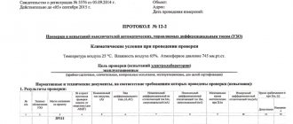
- Climatic conditions during measurements
- Purpose of inspection (acceptance, control, operational tests)
- Standard measurement base (RD, SO, PUE)
- Type and nature of soil
- Rated voltage of the electrical installation (up to 1000V, up to and over 1000V, over 1000V)
- Neutral mode (isolated, grounded)
- Soil resistivity
- The measurement results are displayed in the following table
Sometimes the table is supplemented with standard resistance data (permissible value, correction factor and final normalized value).
9. Table with measuring device data
10. Conclusion on the compliance of the grounding device with the requirements of the rules.
In conclusion, we offer you a couple of ready-made examples of Prokotlov No. 3 for checking the resistance of the grounding device in .doc format
Interesting materials on this topic:
Lightning protection passport
The lightning protection passport is practically no different from the protocol. What does it include? When is certification required? And also about how the corresponding measurement protocols are filled in.
Norms, rules and GOSTs for lightning protection - regulatory documents
On Russian standards in the field of lightning protection. A group of IEC standards and their comparison with domestic ones.
Lightning protection grounding resistance
What should be the maximum resistance for different lightning protection categories? Table of resistivity of various soils. About measuring ground resistance and frequency of checks.
Requirements for external lightning protection elements
What tests do traditional lightning protection system components undergo? Description of testing techniques that simulate natural atmospheric conditions and the effects of corrosion on components.
Source
| Resistivity, average value (Ohm* m) | |
| Basalt | 2 000 |
| Concrete | 40 — 1 000 |
| Water | |
| Sea water | 0,2 |
| Pond water | 40 |
| Lowland river water | 50 |
| Ground water | 20 — 60 |
| Permafrost soil (permafrost soil) | |
| Permafrost soil - thawed layer (near the surface in summer) | 500 — 1000 |
| Permafrost soil (loam) | 20 000 |
| Permafrost soil (sand) | 50 000 |
| Clay | |
| Clay wet | 20 |
| Semi-solid clay | 60 |
| Gneiss decomposed | 275 |
| Gravel | |
| Clay gravel, heterogeneous | 300 |
| Homogeneous gravel | 800 |
| Granite | 1 100 — 22 000 |
| Graphite chips | 0,1 — 2 |
| Grass (fine crushed stone/coarse sand) | 5 500 |
| Ash, ashes | 40 |
| Surface limestone | 3 000 — 5 000 |
| IL | 30 |
| Coal | 150 |
| Quartz | 15 000 |
| Coke | 2,5 |
| Loess (yellow soil) | 250 |
| Chalk | 60 |
| Marl | |
| Common marl | 150 |
| Clay marl (50 - 75% clay particles) | 50 |
| Sand | |
| Sand heavily moistened by groundwater | 10 — 60 |
| Sand, moderately moistened | 60 — 130 |
| Wet sand | 130 — 400 |
| The sand is slightly damp | 400 — 1 500 |
| Sand dry | 1 500 — 4 200 |
| Sandy loam (sandy loam) | 150 |
| Sandstone | 1 000 |
| garden soil | 40 |
| Saline | 20 |
| Loam | |
| Loam, highly moistened by groundwater | 10 — 60 |
| Semi-solid loam, forest-like | 100 |
| Loam at a temperature of minus 5 C° | 150 |
| Sandy loam (sandy loam) | 150 |
| Graphite slate | 55 |
| Sandy loam (sandy loam) | 150 |
| Peat | |
| Peat at a temperature of 10° | 25 |
| Peat at 0 C° | 50 |
| Chernozem | 60 |
| Crushed stone | |
| Wet crushed stone | 3 000 |
| Dry crushed stone | 5 000 |
Electrolaboratory in Rostov
Our electrical laboratory specialists, electrical laboratory engineers in Rostov-on-Don, carry out work on a complex of electrical measurements, electrical measurements, resistance measurements with the issuance of a technical report on resistance measurements, thermal imaging inspection using a thermal imager (heat losses in apartments, houses)
Let's look at why an electrical laboratory is needed, and whether it is generally worth carrying out all these resistance measurements and electrical measurements, electrical measurements, and testing of an electrical laboratory.
When delivering electricity to the consumer, many different electrical equipment are involved in the power supply system (cable, wire, junction boxes, power panels, circuit breakers, RCDs, circuit breakers, meters, sockets, switches). Over time, electrical equipment gets tired of continuous operation. And it is waiting for electrical laboratory specialists to be called to it, who will conduct diagnostics (electrical measurements) and identify the causes of a particular defect. The electrical system requires continuous inspection in accordance with PTEEP.
The cable (wire) requires a visual inspection and insulation resistance measurements. A circuit breaker (automatic, RCD, difavtomat) stands guard, first of all, over the cable (wire) from excessive overload in operation and requires attention from the electrical laboratory, insists on measuring the phase-zero circuit, testing circuit breakers (automatic, RCD, difavtomat) ) load. Distribution boxes hide from us the places where the cable (wire) branches to the electrical consumer and the places where electricity transfers from one cable to another. In the distribution boxes there are clamps that connect the cable (wire) to each other. These places require preventive inspection. It is strictly forbidden to connect cable wires by twisting. Grounding measurement allows you to identify electrical equipment that is not grounded due to various reasons; the compressive contact in a socket, lamp, junction box or other electrical equipment has weakened.
Sockets, switches, lamps, electric motors, heating elements, as well as other electrical equipment included in the power system require increased attention from the electricity consumer, since at the places where the cable (wire) is connected to this equipment, the compression screws loosen and the connection area heats up , which entails melting of the ends of the cable (wire), overheating of the equipment (socket, switch, lamp, compressor) and leads to a fire.
When carrying out a set of electrical measurements (measuring resistance, insulation), electrical laboratory specialists identify a lot of faults. Measuring the insulation resistance reveals the suitability of a given cable (wire) for further use. And if the cable (wire) has low insulation resistance, then it must be replaced. Our electrical installation specialists will help you with this.
Measuring the “phase-zero” loop and testing the circuit breakers (circuit breakers), (automatic, RCD, differential) with a load allows you to determine the performance of the protection of your power system.
A special loading device for ABB circuit breakers allows us to test ABB circuit breakers of any rating
Measuring the metallic connection of elements with the grounding loop will make it possible to determine ungrounded (not zeroed) elements of the electrical installation.
For all electrical measurements, the electrical laboratory issues test reports and a technical report on electrical measurements. If necessary, we can draw up a single-line power supply diagram.
Our electrical laboratory in Rostov-on-Don makes real measurements and examinations of electrical systems. For large volumes, electrical laboratory specialists can travel to any city and carry out electrical measurements (electrical measurements), testing electrical equipment, and setting up relay protection in a short time. Our electrical laboratory department employs 8 people.
If you need to make electrical measurements, insulation measurements, resistance measurements, drawing up a single-line diagram -
call +7(906)18-49-221
If necessary, when defects are detected, electrical laboratory specialists can put the electrical wiring in order on their own.
What does the protocol for measuring ground resistance look like?
Similar
This document has several required elements - in particular, it contains a table that includes information about the installation being tested and the parameters obtained. In addition, the electrical laboratory employee indicates the conditions under which the study was carried out, such as ambient temperature and humidity, soil condition and type.
The protocol for measuring ground resistance cannot be valid without indicating information about the customer and the address where his facility is located. It also contains detailed information about the organization that is responsible for performing this type of work. It is worth remembering that the laboratory must be a member of the SRO and have all the relevant approvals from it, which give the validity of this documentation.