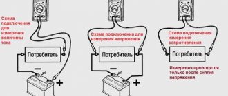
Basic types of transistors
There are two main types of transistors - bipolar and field-effect. In the first case, the output current is created with the participation of carriers of both signs (holes and electrons), and in the second case - only one. Testing the transistor with a multimeter will help determine the malfunction of each of them.
Bipolar transistors are essentially semiconductor devices. They are equipped with three pins and two pn junctions. The operating principle of these devices involves the use of positive and negative charges - holes and electrons. Flowing currents are controlled using a specially dedicated control current. These devices are widely used in electronic and radio engineering circuits.
Bipolar transistors consist of three-layer semiconductors of two types - “p-p-p” and “p-p-p”. In addition, the design has two pn junctions. The semiconductor layers are connected to external terminals through non-rectifying semiconductor contacts. The middle layer is considered the base, which is connected to the corresponding pin. Two layers located at the edges are also connected to the outputs - the emitter and collector. In electrical circuits, an arrow is used to indicate the emitter, indicating the direction of current flowing through the transistor.
In different types of transistors, holes and electrons - carriers of electricity - can have their own functions. The most common type is p-p-p due to the best parameters and technical characteristics. The leading role in such devices is played by electrons, which perform the main tasks of ensuring all electrical processes. They are approximately 2-3 times more mobile than holes, and therefore have increased activity. Qualitative improvements in devices also occur due to the collector junction area, which is significantly larger than the emitter junction area.
Each bipolar transistor has two pn junctions. When testing a transistor with a multimeter, this allows you to check the performance of the devices by monitoring the resistance values of the transitions when direct and reverse voltages are connected to them. For normal operation of the p-p-p-device, a positive voltage is applied to the collector, under the influence of which the base junction opens. After the base current occurs, the collector current appears. When a negative voltage occurs in the base, the transistor closes and the current flow stops.
The base junction in pnp devices opens when exposed to negative collector voltage. Positive voltage causes the transistor to turn off. All the necessary collector characteristics at the output can be obtained by smoothly changing the current and voltage values. This allows you to effectively test the bipolar transistor with a tester.
There are electronic devices in which all processes are controlled by the action of an electric field directed perpendicular to the current. These devices are called field-effect or unipolar transistors. The main elements are three contacts - source, drain and gate. The design of the field-effect transistor is complemented by a conductive layer that acts as a channel through which electric current flows.
These devices are represented by modifications of the “p” or “p”-channel type. Channels can be located vertically or horizontally, and their configuration can be volumetric or near-surface. The latter option is also divided into inversion layers containing enriched and depleted ones. The formation of all channels occurs under the influence of an external electric field. Devices with near-surface channels have a metal-dielectric-semiconductor structure, which is why they are called MOS transistors.
Checking a bipolar transistor with a multimeter
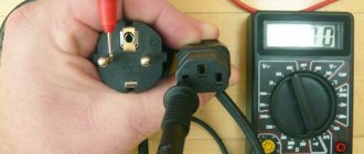
The functionality of the bipolar transistor can be checked using a digital multimeter. This device measures direct and alternating currents, as well as voltage and resistance. Before starting measurements, the device must be properly configured. This will allow you to more effectively solve the problem of how to test a bipolar transistor with a multimeter without desoldering.
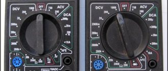
Modern multimeters can operate in a special measurement mode, which is why a diode icon is displayed on the body. When the question of how to check a bipolar transistor with a tester is decided, the device switches to the semiconductor testing mode, and one should be displayed on the display. The device terminals are connected in the same way as in resistance measurement mode. The black wire is connected to the COM port, and the red wire is connected to the output that measures resistance, voltage and frequency.
Older multimeters may not have a diode and transistor test feature. In such cases, all actions are carried out in the resistance measurement mode set to maximum. The multimeter battery must be charged before use. In addition, you need to check the serviceability of the probes. To do this, their tips are connected to each other. The squeak of the device and the zeros shown on the display indicate that the probes are working properly.
Checking a bipolar transistor with a multimeter is performed in the following order:
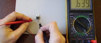
- First of all, you need to correctly connect the leads of the multimeter and the transistor. To do this, you need to determine exactly where the base, collector and emitter are located. To determine the base, a black probe is connected to the first electrode, which is presumably considered the base. Another red probe is alternately connected first to the second and then to the third electrode. The probes are swapped until the device detects a voltage drop. After this, the bipolar transistor is finally checked with a multimeter and the pairs are determined: “base-emitter” or “base-collector”. The emitter and collector electrodes are determined using a digital multimeter. In most cases, the voltage drop and resistance at the emitter junction are higher than at the collector junction.
- Definition of a base-collector pn junction: the red probe is connected to the base, and the black probe is connected to the collector. This connection operates in diode mode and allows current to flow in only one direction.
- Definition of a base-emitter pn junction: the red probe remains connected to the base, and the black probe must be connected to the emitter. Just as in the previous case, with this connection, current flows only when connected directly. This is confirmed by checking the NPN transistor with a multimeter
- Definition of an emitter-collector pn junction: if this junction is in good working order, the resistance in this section will tend to infinity. This is indicated by the unit shown on the display.
- The multimeter is connected to each pair of contacts in two directions. That is, transistors of the pnp type are checked by connecting them back to the probes. In this case, a black probe is connected to the base. After measurements, the results obtained are compared with each other.
- After checking the pnp transistor with a multimeter, the performance of the bipolar transistor is confirmed when, when measuring one polarity, the multimeter shows the final resistance, and when measuring the reverse polarity, one is obtained. This test does not require desoldering the part from the common board.
Read also: Bit numbers for self-tapping screws
Many people are trying to solve the question of how to test a transistor without a multimeter using light bulbs and other devices. This is not recommended, since the element is highly likely to fail.
How to check a transistor with a multimeter
Many modern testers are equipped with specialized connectors, which are used to test the functionality of radio components, including transistors.
To determine the operating condition of a semiconductor device, it is necessary to test each of its elements. A bipolar transistor has two p-n junctions in the form of diodes (semiconductors), which are connected back to back to the base. Hence, one semiconductor is formed by the collector and base terminals, and the other by the emitter and base.
When using a transistor to assemble a circuit board, you must clearly know the purpose of each pin. Incorrect placement of the element may cause it to burn out. Using a tester, you can find out the purpose of each pin.
Checking the functionality of the field-effect transistor
Field-effect transistors are widely used in audio and video equipment, monitors and power supplies. The functioning of most electronic circuits depends on their performance. Therefore, in case of any malfunctions, these elements are checked in various ways, including checking transistors without desoldering them from the circuit with a multimeter.
A typical field-effect transistor circuit is shown in the figure. The main terminals - gate, drain and source - can be located differently, depending on the brand of transistor. If there is no marking, it is necessary to clarify the reference data regarding a particular model.
The main problem that arises when repairing electronic equipment with field-effect transistors is checking the transistor with a multimeter without desoldering. As a rule, faults concern high-power field-effect transistors, which are used in switching power supplies. In addition, these devices are very sensitive to static discharges. Therefore, before deciding how to test a transistor on a board with a multimeter, you should wear a special antistatic bracelet and familiarize yourself with the safety rules when performing this procedure.
Testing using a multimeter involves the same actions as for bipolar transistors. A working field-effect transistor has an infinitely large resistance between the terminals, regardless of the test voltage applied to it.
However, solving the question of how to ring a transistor with a multimeter has its own characteristics. If the positive probe of the multimeter is applied to the gate, and the negative probe to the source, then in this case the gate capacitance will be charged and the junction will open. When measuring between the drain and the source, the device shows the presence of a small resistance. Sometimes electrical engineers, in the absence of practical experience, may consider this a malfunction, which is not always true. This may be important when testing a horizontal transistor with a multimeter. Before testing the drain-source channel, it is recommended to short-circuit all terminals of the field-effect transistor to discharge the junction capacitances. After this, their resistance will increase again, after which you can re-test the transistors with a multimeter. If this procedure does not give a positive result, then this element is inoperative.
In field-effect transistors used for high-power switching power supplies, internal diodes are often installed at the drain-source junction. Therefore, during testing, this channel exhibits the properties of a conventional semiconductor diode. Therefore, to exclude an error, before checking the serviceability of the transistor with a multimeter, you should make sure that the internal diode is present. After the first check, the multimeter probes need to be swapped. After this, a unit will appear on the screen, indicating infinite resistance. If this does not happen, there is a high probability of a malfunction of the field-effect transistor. Using the device, you can not only check, but also measure the transistor with a multimeter.
Checking with a multimeter
Using a multimeter, you can check the KT315, and indeed any semiconductor triode, in two stages. At the first stage, you need to look at the state of the pn transitions between the base and other pins. As you know, the pn junctions of a transistor consist of two diodes. To check them, you need to set the multimeter to the diode measurement mode.
Next, attach the positive “+” probe of the multimeter to the base, and the negative “-” probe to any of the electrodes. If the transitions are working, then the voltage drop across them should be in the range of 500-700 millivolts. When connecting the tester differently, when the negative probe is installed on the base, one should be displayed on the multimeter screen. One indicates an infinitely large junction resistance. If these conditions are not met, then the transistor does not pass the first stage of testing and is considered faulty.
The voltage drop at the base-emitter junction must be greater than at the base-collector junction. This is usually how his contacts define him.
At the second stage, the conductivity between the collector and emitter terminals is checked. The probes are applied in different ways between these electrodes, and a unit should be displayed on the multimeter. If this is not the case, the semiconductor device is faulty.
How to test a compound transistor with a multimeter
A compound transistor or Darlington transistor is a circuit that combines two or more bipolar transistors. This allows you to significantly increase the current gain. Such transistors are used in circuits designed to operate with high currents, for example, in voltage stabilizers or output stages of power amplifiers. They are necessary when it is necessary to provide a large input impedance, that is, total complex resistance.
The general conclusions of a composite transistor are the same as those of the bipolar model. The NPN transistor is checked in exactly the same way with a multimeter. In this case, a technique similar to testing a conventional bipolar transistor is used.
In the world of electronics, there are a large number of different devices and parts. They number in the millions and are constantly increasing with the invention of more and more new devices.
Read also: Mechanical press for waste paper
Despite the large number of electronic elements, every specialist in this field knows about transistors. This is a radio-electronic device operating at special frequencies, which has 3 outputs. Its job is to reduce current resistance.
As you might have guessed, today we will talk about how to test a transistor with a multimeter.
Brief contents of the article:
Checking the transistor with a multimeter. Description of the technique
Any radio amateur knows that the performance of the future radio-electronic device depends on initially serviceable radio components, be it transistors, diodes, capacitors. Previously, we looked at the issue of checking a diode with a multimeter. In this article, we will look at what it is to check a transistor with a multimeter and provide a simple way to check its serviceability with a multimeter.
In fact, to determine the health of a bipolar transistor, we just need to measure its static current transfer coefficient - h21e.
The value of this coefficient shows the degree of gain of a given transistor. It is called static due to the fact that it is measured at a constant voltage at its terminals, as well as at constant currents in the circuit circuits. The letter “E” indicates that it is included in the OE type scheme. The higher the numerical indicator h21e, the greater the degree of amplification of a given transistor.
Where should I start?
Before you start working with a multimeter, you need to know how to use it, know what model you are using, and also be able to connect it to the network.
You can find out what model you are using by looking at its markings.
Usually the marking is on the box of the device and there is complete information about it, namely:
- Transistor model.
- Manufacturer country.
- Issuing company.
- Product warranty.
If for some reason you do not have a transistor box, you can fix this by searching for a similar photo on the Internet, where there will be a detailed description of the device.
Checking a bipolar transistor with a multimeter
Next we will talk about instructions on how to test a transistor:
- Attach the large red probe (CEM) - this will be considered a minus, and attach the black one to (MA) - this will be a plus.
- Next, you need to turn on the device and redirect it to the dialing mode or you can switch it to the resistance mode at your discretion.
- After which you will see the energy resistance value on the screen. Normally, it ranges from 0.3 to 0.7 Ohm.
- To display the minimum resistance, you need to indicate the power of your transition, and after all that has been done, your device is fully configured and ready for its active and long-term use.
How to test a transistor without desoldering it?
Soldering any part from an electrical appliance is a very responsible matter, in which the slightest mistake can completely damage any electrical appliance.
So how can you test a transistor without desoldering it from the circuit?
- First you need to ensure its integrity.
- Then check its generation.
- Next, you should pay attention to L2, which is located near the opening of the red probes.
- The glow of lamp L2 indicates its performance.
If lamp L2 does not light, then this is a sure sign that the device is broken. In this case, it is not recommended to repair it yourself, since there is a high probability that you will damage other parts during the repair.
We advise you to contact a competent specialist with this problem who can repair the transistor.
How to check a transistor for serviceability
To check the transistor with a multimeter for serviceability, it will be enough to measure the reverse and forward resistance of two semiconductors (diodes), which we will now do.
In a transistor, there are usually two junction structures pnp and npn .
Pnp is an emitter junction, you can determine this by the arrow that points to the base.
The arrow that goes from the base indicates that this is an npn transition.
The Pnp junction can be opened using a negative voltage that is applied to the base.
We set the multimeter operating mode switch to the resistance measurement position on o.
We connect the black negative wire to the base terminal, and connect the red positive wire in turn to the emitter and collector terminals.
Those. We check the functionality of the emitter and collector junctions.
A multimeter reading between 0.5 and 1.2 kOhm will tell you that the diodes are intact.
Now we swap the contacts, connect the positive wire to the base, and alternately connect the negative wire to the emitter and collector terminals.
There is no need to change the multimeter settings.
The last reading should be much higher than the previous one. If everything is normal, then you will see the number “1” on the device display.
This suggests that the resistance is very high, the device cannot display data above 2000 Ohms, and the diode junctions are intact.
The advantage of this method is that the transistor can be tested directly on the device without unsoldering it from there.
Although there are still transistors where low-resistance resistors are soldered into the pn junctions, the presence of which may not allow for correct resistance measurements; it can be small, both at the emitter and collector junctions.
In this case, the leads will need to be unsoldered and measurements taken again.
Checking the transistor on the board
Now we move on to how to test the transistor on the board? It should be noted that this is one of the most popular questions on this topic.
There are many answers to this question on the Internet, but not all are correct from the point of view of physics and engineering. Testing the transistor on the board is as follows:
It must first be connected to the positive base using a powerful source. If you do everything correctly, your light should light up.
Not a single modern circuit can do without semiconductor devices. The most common of them is a transistor and it is this that often fails. The reason for this is voltage drops that exist in our networks, loads, etc. Let's consider two ways to check the serviceability of a transistor using a multimeter.
Required minimum information
To understand whether a bipolar transistor is working or not, we need to know at least in the most general terms how it works and works. This is an active electronic component, which is a semiconductor device. There are two main types - NPN and PNP. Each of them has three electrodes: base, emitter and collector.
Types of transistors and operating principle
The principle of operation of transistors can be briefly formulated in this way: it is a controlled electronic switch. It passes current in the direction from the collector to the emitter in the case of NPN type and from the emitter to the collector in PNP when there is voltage at the base. Moreover, by changing the potential at the base, we change the degree of “openness” of the junction, adjusting the amount of current passed. That is, if more current is supplied to the base, we have a larger collector-emitter current, reduce the potential at the base, and reduce the current flowing through the transistor.
Another important thing to know is that current cannot flow in the opposite direction. And it doesn’t matter whether there is potential on the base or not. It always flows in the direction indicated by the arrow in the diagram. Actually, this is all the information we need to know how the transistor works.
What is a transistor
The main component in any electrical circuit is a transistor, which, under the influence of an external signal, controls the current in the electrical circuit. Transistors are divided into two types: field-effect and bipolar.
Transistor is one of the main components of microcircuits and electrical circuits
A bipolar transistor has three terminals: base, emitter and collector. A small current is supplied to the base, which causes a change in the emitter-collector resistance zone, which leads to a change in the flowing current. The current flows in one direction, which is determined by the type of transition and corresponds to the polarity of the connection.
This type of transistor is equipped with two pn junctions. When electronic conductivity (n) predominates in the outer region of the device, and hole conductivity (p) predominates in the middle region, the transistor is called npn (reverse conductivity). If it’s the other way around, then the device is called a pnp (direct conduction) transistor.
Field-effect transistors have characteristic differences from bipolar ones. They are equipped with two working terminals - source and drain and one control terminal (gate). In this case, the gate is affected by voltage rather than current, which is typical for the bipolar type. Electric current flows between source and drain with a certain intensity, which depends on the signal. This signal is generated between gate and source or gate and drain. A transistor of this type can be with a control pn junction or with an insulated gate. In the first case, the working leads are connected to a semiconductor wafer, which can be p- or n-type.
The principle of operation of a field-effect transistor
The main feature of field-effect transistors is that they are controlled not by current, but by voltage. The minimal use of electricity allows it to be used in radio components with quiet and compact power supplies. Such devices may have different polarities.
Tsokolevka
Medium and high power bipolar transistors have basically the same pinout, from left to right - emitter, collector, base. It is better to check for low power transistors. This is important because when determining performance, we will need this information.
Appearance of a medium power bipolar transistor and its pinout
That is, if you need to determine whether a bipolar transistor is working or not, you need to look for its pinout. If you want to make sure or don’t know where the “face” is, then look for information in a reference book or type the “name” of your semiconductor device on your computer and add the word “datasheet”. This is a transliteration from English Datasheet, which translates as “technical data”. For this request, you will receive a list of characteristics of the device and its pinout.
Read also: Melting point of aluminum foil
How to test a transistor with a multimeter with a built-in function
Let's start with the fact that there are multimeters with the function of checking the functionality of the transistor and determining the gain. They can be identified by the presence of a characteristic block on the front panel. It has a socket for installing a transistor, a round colored plastic insert with holes for the legs of a semiconductor device. The color of the insert can be any, but usually it stands out.
First of all, move the range switch (large knob) to the appropriate position. The mode can be identified by the inscription - hFE. Before checking the transistor with a multimeter, we determine the NPN or PNP type.
Multimeter with transistor test function
Next, we consider the connectors into which the electrodes must be inserted. They are signed in Latin letters: E - emitter, B - base, C - collector. In accordance with the inscriptions, we place the leads of the semiconductor element into the sockets. After a few moments, the measurement result is displayed on the screen; this is the gain of the transistor. If the device is faulty, there will be no readings, the transistor is faulty.
As you can see, it’s easy to check whether a transistor is working or not with a multimeter with a built-in testing function. But not all electrodes fit into the sockets properly. It is convenient to install transistors with thin leads S9014, S8550, KT3107, KT3102. For large ones, you need to change the shape of the terminals with tweezers or pliers, but you can’t check the transistor on the board that way. In some cases, it is easier to check the transitions of the transistor in the continuity mode and determine its serviceability.
How to check a transistor with a multimeter without desoldering
How to test a bipolar transistor with a multimeter
There are many instruments for testing any type of transistor. They can check not only the serviceability of the transistor, but also select the required gain h21e.
Transistor check
However, for repairing household appliances and electronics, one multimeter is enough. To understand the process of testing a transistor, it would be useful to know what a transistor is and how it works. A transistor can be thought of as two back-to-back diodes having pn junctions. For pnp transistors, the equivalent circuit looks like two diodes connected with cathodes facing each other, and for npn structures the diodes are connected with anodes facing each other.
Transistor equivalent circuits
So you can imagine a simplified equivalent version of the transistor. Briefly about the principle of operation of the transistor. When an alternating signal is applied to the base of the transistor (the common end of the diode connection), the resistance of the collector-base and emitter-base transitions changes. Accordingly, the total resistance of the transitions changes according to the law of the input signal. The constant voltage of the power supply applied to the collector and emitter will also vary according to the law of the input signal.
But the power source voltage applied to the emitter-collector junction of the transistor is significantly greater than the signal arriving at the base. The output signal is taken from the emitter and collector terminals. This is how a transistor works in amplification mode. In key mode, a minimum signal is supplied to the base, at which the transistor is closed, and a maximum signal, which completely opens the transistor.
How to test a pnp transistor with a multimeter
Bipolar transistors can be of forward conductivity pnp and reverse conductivity npn. In the diagram, the conductivity of pnp junctions is indicated by an arrow towards the base, and npn junctions are reflected by an arrow indicating the direction from the base. To check the transistor on a multimeter, select a resistance measurement limit of 2000 Ohms or “continuity”.
Finding the reverse resistance of the transitions
The minus of the multimeter is applied to the base of the transistor, and the plus alternately to the collector and emitter terminals. The normal junction resistance will be in the range of 400 - 1200 Ohms. To check the collector-base and emitter-base transitions for reverse resistance, apply the plus of the multimeter to the base, and the minuses to the emitter and collector in turn.
The collector and emitter reverse resistance should be high and the multimeter will read “1”. To check a transistor with reverse polarity npn, apply the plus of the multimeter to the base, but otherwise the technique is the same as when checking pnp polarity. Using the same method, you can check the functionality of the transistors without removing them from the board.
Sometimes transistor junctions in a circuit can be bridged with a small resistance. Then it is better to unsolder the base or the entire transistor, since the multimeter readings when checking for the integrity of the element will be incorrect. If the transitions of the transistor in both directions show zero or close to it, then this indicates a breakdown of the transitions, and a reading of “1” on the multimeter indicates a break in the transitions.
How to find the pinout of a transistor with a multimeter
The location of the terminals (pinout) of the transistor can be found in a reference book or by type of transistor on the Internet. You can also determine the location of the pins with a multimeter. To do this, apply the plus of the multimeter to the right terminal of the transistor, and the minus to the middle and left contacts.
How to find the emitter and collector
Let's assume that the resistance in both dimensions is infinity. It turns out that we have found the reverse resistance of two npn junctions. Thus, we got to the base. To find the collector and emitter, place the minus on the base, and touch the two remaining terminals in turn with the plus.
The display showed transition resistance values of 816 Ohms and 807 Ohms. A terminal with a resistance of 807 ohms will be a collector because the base-collector junction has a lower resistance value than the base-emitter junction. There are also medium and high power transistors; their collector is connected to the body or to a metal plate designed to dissipate heat.
How to check a powerful bipolar transistor and its pinout!!!
Check on board
To check the transistor with a multimeter without desoldering, you need a multimeter with a diode continuity function. We move the switch to this position, the connection of the probes is standard: black to the common link (COM or with a ground symbol), red to the middle (socket for measuring resistance, current, voltage).
How to check a transistor with a multimeter without desoldering
To understand the principle of testing, we need to remember the structure of bipolar transistors. As already mentioned, they come in two types: PNP and NPN. That is, these are three consecutive areas with two transitions, united by a common area - the base.
The structure of a bipolar transistor and how it can be represented in order to understand how we will test it
Conventionally, we can imagine this device as two diodes. In the case of the PNP type they are turned on towards each other, in the case of NPN they are in mirror image. This representation is in the picture in the right column and in no way reflects the structure of this semiconductor device, but explains what we should see when making a call.
Testing a PNP type bipolar transistor
So, let's start by checking the PNP type bipolar. This is what we should get:
- If you apply a plus (red probe) to the base and a minus (black probe) to the emitter or collector, there should be an infinitely large resistance. In this case, the diodes are closed (see the equivalent circuit).
- If we apply minus to the base (black probe), and plus to the emitter or collector (red probe), we see a current from 600 to 800 mV. In this case, it turns out that the transition is open.
Checking a bipolar PNP transistor with a multimeter
So, the PNP transistor will be open only when positive is applied to the emitter or collector. If there are any deviations during testing, the element is inoperable.
Testing the serviceability of the NPN transistor
As you can see, in an NPN device the situation will be different. In practice it is diametrically opposite:
- If you apply a plus (red probe) to the base, and a minus to the emitter or collector, the junction will be open, and readings will appear on the screen - from 600 to 800 mV.
- If you swap the probes: plus to the collector or emitter, minus to the base, the transitions are locked, there is no current.
- When touching the emitter and collector with the probes, there should still be no current.
Checking the functionality of a bipolar NPN transistor with a multimeter
As you can see, this device works in the opposite direction. In order to understand whether a transistor is working or not, you need to know its type. This is the only way we can check the transistor with a multimeter without desoldering it from the board.
And once again we draw your attention to the fact that pictures with diodes do not in any way reflect the design of this semiconductor device. They are needed only to understand what we should see when checking transitions. This makes it easier to remember and understand the readings on the multimeter screen.
How to identify base, collector and emitter
Sometimes there are situations when you don’t have a reference book at hand and you don’t have the ability to find the pinout on the Internet, and the inscription on the transistor body has become unreadable. Then, using circuits with diodes, you can experimentally find the base and determine the type of device.
The structure of a bipolar transistor and how it can be represented to understand how we will test it
By searching, we look for the position of the probes at which all three electrodes “ring”. The conclusion regarding which the readings appear on the other two will be the base. Therefore, plus or minus is applied to the base, we determine the type, PNP or NPN. If we apply a plus to the base, it is an NPN type, if a minus is applied, it is a PNP.
To determine where the emitter is and where the collector is, you need to compare the multimeter readings during measurement. There is always more current at the emitter. So we will find the base, emitter and collector empirically.