There is no call from the video intercom when you press the call button on the outdoor video panel
We need to determine what is faulty: the video intercom, connecting cable or video panel.
A little theory: the electrical command for a video intercom about a call is to reduce the DC voltage in the audio wire (relative to the total) to a level of less than 1V. In standby or conversation mode, the voltage in the audio wire can range from 4 to 10V (depending on the video intercom model).
In practice, we do the following: we briefly short-circuit the “audio” and common wire directly at the external video panel.
The lock release function does not work
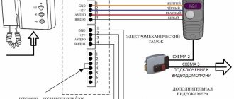
A little theory: the electrical command to open the lock is to increase the DC voltage in the audio wire (relative to the common wire) to a level of more than 11.5V. This statement is acceptable for video intercoms Commax, Gardi, Kocom, Qualvision, Slinex, Arni and the like. At this voltage level, the relay in the video panel is activated, and its contacts will supply current (from the power supply or storage device) to the electromagnetic lock.
Determining the malfunction comes down to measuring the DC voltage in the audio wire (relative to the general one) with a tester at the moment of pressing the lock release button when the video intercom is turned on (there is an image on the screen). If the measured voltage does not rise to a level of more than 11.5V, then the video intercom is faulty. If the voltage (measured at the video panel) is more than 11.5V, then it is necessary to determine whether the video panel, the lock's power system (additional power supply or storage device) or the lock itself is faulty. An electromagnetic lock can be checked this way: briefly apply 12V voltage to it from a known-good power supply or battery. If the lock is working properly, and the voltage in the audio wire on the video panel rises to a level above 11.5V when the lock release button is pressed, then the video panel or the additional power supply for the lock (or drive) is faulty.
It should be noted that there are a number of video panels whose output does not produce a short circuit with the relay when the lock opening button is pressed, but voltage that is supplied directly to the electromagnetic lock. Using the output voltage directly to open the lock does not always lead to stable operation of the electromagnetic lock. In this case, we recommend using an intermediate electromagnetic relay. The relay coil is connected to the output of the video panel, and the relay contacts are connected to the drive and the lock. The relay must be used with a coil at a voltage of 12V, and its contacts must have a current of at least 5A.
Repair of intercom tubes
The owner of the apartment cannot control access to the residential premises. If the intercom device does not work only in a certain apartment, the likelihood that the handset has failed is very high.
The main types of breakdowns of this spare part are:
- It is impossible to hear from any of the parties to the negotiation process;
- Broken cable (twisted pair);
- The tongue sinks.
- The intercom button for opening the front door does not work;
The answer to the question: “Why do such malfunctions occur and how to prevent them?” - only a specialist can give.
It is important to remember that a malfunction can be present in any mechanism.
As practice shows, the body base of the tube or its attachment point often breaks.
In this case it is necessary
How to fix an intercom in an apartment
If any module has external damage and does not work, partial or complete replacement of these elements is required. If the intercom does not respond to a magnetic key or to key presses, you should check the power circuits and repair the broken contact.3.
If calls from the call panel are not switched correctly or are not switched at all, and the door lock does not work, the subscriber device may be faulty.
First, on the switch you need to find the terminals marked “E” and “D” (units and tens of coordinate wiring), and measure the resistance one by one
Repair of the “Visit” intercom – when to call a specialist, and when can you do it yourself?
The capabilities of this chip are as follows:
- Monitor and regulate the opening/closing time of the lock;
- Write information about the keys into memory one by one;
- Record key data on external media;
- Notify with sound about significant actions, microcircuit malfunctions;
- Connect to a computer and transfer data to it.
- Recording an admin key;
- Selectively and completely erase information about codes and keys;
- Collect data and select the lock type;
To summarize, we can say that controllers are an important part of an electromagnetic lock, storing significant amounts of data that allow for intelligent control of locking devices. Connecting an electromagnetic lock to Vizit KTM-600 and RFID KTM-600R Connecting an electromechanical lock to Vizit KTM-600 and RFID KTM-600RWatch an exciting and useful quest in two parts
The intercom button does not work - troubleshooting
This will avoid mistakes when replacing parts.
Here is a diagram for connecting the Metakom TKP-12M intercom handset: Let's look at the procedure for performing the work using the example of repairing the button of the most common Metakom TKP-12M intercom: Turn off the intercom, disconnect the wires.
It is important to maintain the polarity of the connection in the future.
To do this, you can put a mark on one of the wires with a marker or felt-tip pen; We disassemble the device body by unscrewing the mounting screws on the back cover of the device; Unsolder the old microswitch.
To do this, insert the end of a flat-head screwdriver between the switch body and the board, and on the reverse side heat both legs at once with a soldering iron. Then gently press the microswitch away from the board until one half is completely disconnected. Solder the remaining 2 legs in the same way; Solder a new microswitch.
How to repair an intercom handset with your own hands
But almost all models have one weak point - its holder. True, in some devices it only performs the function of a “hook” to hold its weight on the base, while in others, an additional tongue is installed that includes an intercom. In all cases, it will help us out.
Otherwise, the circuit may turn out to be either permanently turned off, or, conversely, turned on and will not be able to work in normal mode. To perform this operation, you do not need any specific knowledge, you just need to know how to work with a soldering iron. In the same way, you can solder the plastic parts inside
Intercom handset connection diagram Visit: description of possible difficulties
This device includes the following elements:
- handset body; button for switching call volume; button for opening the lock; speaker and microphone; electronic control board; handset holder.
Design of the Vizit intercom handsetDespite the fact that intercom intercom devices are highly reliable, it happens that they fail for one reason or another. To independently replace the handset, having a Visit intercom, the handset connection diagram will be as follows. Initially, the apartment intercom is connected to the intercom system line.
It is important to observe polarity when connecting the patch cable. After this, the handset holder is secured to a wall or other vertical
The intercom handset does not work visit
You can find it by looking at the cables. They lead from subscriber devices. In simple terms: a switch is a block into which a lot of cables go (if we are talking, of course, about a multi-party intercom). Device diagnostics begin with the same visual analysis and checking the power supply, the integrity of the wires, etc.
If in this case the fault has not been resolved, then you need to contact more qualified specialists. The final stage is to check the intercom subscriber devices. Armed with a tester with an ohmmeter function, you need to do the following: inspect the device and find the terminal blocks to which many wires fit, those marked with the letter E - this is the units digit, and the letter D - the tens digit.
Intercom repair. What are the common causes of breakdowns?
The damage is easy to fix yourself. If there are no visible signal breaks, but the switch is suspected of being faulty, the check should be done by a technician.
Attention! If the intercom doesn't work, who should I call?
It is recommended to contact the company that installed the device. The company's technicians repair intercom tubes.
A malfunction is possible due to incorrect switching, a complete lack of communication between the external panel on the door and the subscriber. The reason is the subscriber handset - it breaks frequently. If the circuit is coordinated, the switch checks the buses under the symbols “E” and “D”, which are responsible for units and tens, and checks each pair for subscriber handsets.
The standard resistance of devices is in the segment between 600 and 800 Ohms in one direction, and in the other there is no finite value. If any tube does not meet the given resistance values, it is the cause of system failure. The repair consists of correcting the polarity and eliminating the short circuit.
Diagram of an intercom handset - tips on design and repair for beginners
The malfunction may be present in the following components: speaker, microphone, connection wires or electronic board (if present). Often the body base or its attachment point breaks. It’s easier than ever, of course, to purchase a new handset and connect it to the intercom system: in this case, you need to remember which wires were connected and where, since an incorrect connection can cause a malfunction of the entire system.
You can find out more detailed information by watching this video: Also, to connect a new intercom, you may need the connection diagram that comes with the new part. When purchasing a new intercom handset, you must take into account an important feature: the connection diagram - digital or coordinate, as this affects the configuration of the part.
Source: https://ukpravoedelo.ru/remont-trubok-domofona-74558/
Spontaneous call
This malfunction is one of the most “unpleasant” in terms of determining the location of the malfunction, because It happens that it manifests itself unstable. Most often, this problem is hidden in the outdoor video panel, less often in the cable, and very rarely in the video intercom.
To determine, disconnect the audio cable directly from the video panel; if the problem goes away, then the video panel is faulty. If it remains, then disconnect the audio cable from the video intercom itself. The intercom is silent - the problem is in the connecting cable. If the intercom does not go off or rings when the audio cable from it is disconnected, it is the one that is faulty.
Installation and repair of intercom handset. Part 2
Hello dear readers of the site sesaga.ru. In the first part of the article, we figured out how you can eliminate the main malfunctions that arise during the operation of the intercom handset on your own. Today we will continue to analyze faults and ways to eliminate them. As in the first part, I am posting a schematic diagram of the TKP 12M subscriber handset.
You dial a number, press “call”, and it hangs up
Here you will have to sweat a little, as there are enough reasons
.
First of all, pick up the phone and look at the “ plus”
" and "
minus
" coming from the intercom panel so that they are not torn off. If the ends are in place, then we disconnect them and move on.
Remember! The intercom handset has connection polarity. Therefore, when you remove it, be sure to mark the incoming wires: “plus” and “minus”
.
Open the phone. To do this, unscrew the screw that secures the top cover, insert the end of a thin screwdriver into the place where the cord enters, and unclip the latches at the bottom of the tube. Now it won’t be difficult to completely remove the top cover by hand.
Please immediately pay attention that both wires are soldered to the speaker terminals. Over time, it happens that due to poor-quality soldering, wires fall off from the terminals. This is the second reason
, why the call is dropped.
If the wire falls off, solder it. At the same time, we check the integrity of the speaker coil - this is the third reason
for the call being dropped.
We put the multimeter, or any other measuring device, in resistance measurement mode. If everything is in order with the speaker coil, then when you touch the speaker terminals with the probes, you can hear a click, while the coil resistance should be in the range of 40 - 60 Ohms. In my case, the resistance was 42 Ohms.