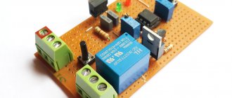
Today's article will be about the process of assembling a simple battery level indicator, but with a more high-precision circuit that is suitable for real-world use and can be a great addition to your car's dashboard.
The indicator is built on the basis of the ELM339 chip, which in turn consists of four separate comparators in a single housing.
The comparator has two inputs and one output, it simply compares the voltage at the inputs, based on this, we get either a logical 0 or one at the output.
The comparator used in the circuit can be found on the boards of the computer power supply, refer to the numbers 339, the letters may differ depending on the manufacturer.
3 mm LEDs are used as indicators.
The circuit works in a very simple way: we have a reference voltage source in the form of a zener diode, chains of resistors are dividers that create a certain voltage at the inputs of the comparators, let's call them threshold.
The comparator constantly compares these voltages with the voltage that forms a divider on resistors R5 and R6, this divider reduces the voltage of the battery under test by three times, if the voltage at the direct input of the comparator is greater than at the inverse input, then at the output we get a logical unit or supply voltage.
The LED lights up, if everything is the other way around, then at the output we get a logical 0 or power ground, the LED in this case does not light up.
The input dividers are selected within a narrow range, since the circuit is designed to work as a charge indicator for 12-volt batteries.
The 4148 low-power diode protects the comparator chip from reverse polarity.
Current-limiting resistors for LEDs are selected with a resistance from 1 to 2.2 kilograms; you can limit yourself to just one resistor.
The printed circuit board is quite compact, I drew it in haste, but the layout is not bad, by the way, you can download it at the end of the article.
To test this board, we need a laboratory power source on which we need to set the voltage to about 13.5 - 14 volts, simulating a fully charged car battery.
- All the LEDs light up at once, gradually reducing the voltage on the power supply, we can observe the LEDs going out at certain voltages.
- When only the red LEDs are lit, the battery is almost empty.
- You can recalculate the input dividers and use the circuit for batteries with a different voltage; by the way, this circuit can also be used in chargers.
- Fee___ download…
- Author; AKA Kasyan
LED battery charge indicator circuit
A battery charge indicator is a necessary thing in the household of any motorist. The relevance of such a device increases many times over when, for some reason, a car refuses to start on a cold winter morning. In this situation, it’s worth deciding whether to call a friend to come and help you start from your battery, or whether the battery has died for a long time, having discharged below a critical level.
Why monitor your battery's condition?
A car battery consists of six batteries connected in series with a supply voltage of 2.1 - 2.16V. Normally, the battery should produce 13 - 13.5V. Significant discharge of the battery should not be allowed, since this reduces the density and, accordingly, increases the freezing temperature of the electrolyte.
The higher the battery wear, the less time it holds a charge. In the warm season, this is not critical, but in winter, side lights forgotten while turned on can completely “kill” the battery by the time it is returned, turning the contents into a piece of ice.
In the table you can see the freezing temperature of the electrolyte, depending on the degree of charge of the unit.
A drop in charge level below 70% is considered critical. All automotive electrical appliances consume current, not voltage. Without load, even a severely discharged battery can show normal voltage. But at a low level, during engine startup, a strong voltage drop will be noted, which is an alarming signal.
It is possible to notice an approaching disaster in a timely manner only if an indicator is installed directly in the cabin. If, while the car is running, it constantly signals about discharge, it’s time to go to the service station.
What indicators exist
Many batteries, especially maintenance-free ones, have a built-in sensor (hygrometer), the operating principle of which is based on measuring the density of the electrolyte.
This sensor monitors the condition of the electrolyte and the relative value of its indicators. It is not very convenient to climb under the hood of a car several times to check the condition of the electrolyte in different operating modes.
Electronic devices are much more convenient for monitoring the condition of the battery.
Types of battery charge indicators
Automotive stores sell many of these devices, differing in design and functionality. Factory devices are conventionally divided into several types.
By connection method:
- to the cigarette lighter socket;
- to the on-board network.
- By signal display method:
- The principle of operation is the same, determining the battery charge level and displaying information in a visual form.
Schematic diagram of the indicator
How to make a battery charge indicator using LEDs?
There are dozens of different control schemes, but they produce identical results. It is possible to assemble such a device yourself from scrap materials. The choice of circuit and components depends solely on your capabilities, imagination and the assortment of the nearest radio store.
Here is a diagram to understand how the LED battery charge indicator works. This portable model can be assembled “on your knee” in a few minutes.
D809 - a 9V zener diode limits the voltage on the LEDs, and the differentiator itself is assembled on three resistors. This LED indicator is triggered by current in the circuit. At a voltage of 14V and above, the current is sufficient to light up all the LEDs, at a voltage of 12-13.5V VD2 and VD3 up, below 12V - VD1 .
- A more advanced option with a minimum of parts can be assembled using a budget voltage indicator - the AN6884 (KA2284) chip .
- Circuit of LED battery charge level indicator on voltage comparator
The circuit operates on the principle of a comparator. VD1 is a 7.6V zener diode, it serves as a reference voltage source. R1 – voltage divider.
During the initial setup, it is set to such a position that all LEDs light up at a voltage of 14V.
The voltage supplied to inputs 8 and 9 is compared through a comparator, and the result is decoded into 5 levels, lighting the corresponding LEDs.
Battery charging controller
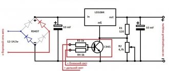
To monitor the condition of the battery while the charger is operating, we make a battery charge controller. The device circuit and components used are as accessible as possible, while at the same time providing complete control over the battery recharging process.
The operating principle of the controller is as follows: as long as the voltage on the battery is below the charging voltage, the green LED lights up. As soon as the voltage is equal, the transistor opens, lighting up the red LED. Changing the resistor in front of the base of the transistor changes the voltage level required to turn on the transistor.
This is a universal monitoring circuit that can be used for both high-power car batteries and miniature lithium batteries.
Please rate the article. We tried our best:) ( 5
Details
The device can use operational amplifiers K140UD6, K153UD2 instead of K553UD2. To obtain high stability of operation, wire wound resistors should be used, for example, SP5-2, SP5-16.
The D219A diodes can be replaced with D220, KD504, KD105, and the KU101A thyristor can be replaced with any of this series, as well as the D235, KU201 series. As relay K1, you can use an automobile relay, the contacts of which allow switching a current of 6 A. Relay K2 - RES10, RES15, RES49 or any other low-power relay with an operating current of no more than 40 mA at a voltage of 6-8 V.
Source: Khodasevich A. G., Khodasevich T. I., Chargers and starting-charging devices, Issue 2.
Battery charge indicator | Homemade catalog
It is very surprising that in many cars, even if they are crammed with all sorts of electronics, there is no banal battery charge indicator . How to determine the battery charge level, especially in winter, when batteries are especially vulnerable?
To solve this problem, I made an indicator, the diagram and assembly of which will not take much time and special professional skills, but the basic skills must be present. Another advantage of the assembly is its low cost compared to cheap Chinese analogues, the quality of which leaves much to be desired.
Types of battery charge indicators
Automotive stores sell many of these devices, differing in design and functionality. Factory devices are conventionally divided into several types.
By connection method:
- to the cigarette lighter socket;
- to the on-board network.
By signal display method:
- analog;
- digital.
The principle of operation is the same, determining the battery charge level and displaying information in a visual form.
Schematic diagram of the indicator
Should you trust the green eye on the battery?
Many modern car batteries have a charge indicator (or, as it is also called, an “eye”). Moreover, the presence of this very “eye” affects the cost - such batteries are more expensive than their “eyeless counterparts”.
But practice shows that the benefit of having such a “peephole” is very doubtful. The built-in charge indicator most often only misleads car owners about the condition of the battery.
Essentially, the “eye” or battery charge indicator is a simplified hydrometer that is installed in only one section of the battery.
What do you need to know about the charge indicator?
In the plastic body of the “eye” there are several balls with different specific gravity and color, and depending on the density, the desired ball floats up. It should be noted right away that there are no light bulbs or tricky microcircuits.
The charge indicator can show three main states - “battery is charged”, “battery is discharged” and “low electrolyte level”.
The indicator shows the charge of the battery if the density is above 1.24 g/cm3, however, these values may differ among different manufacturers. For example, in some batteries it happens that even at 1.20 g/cm3 the “eye” shows the “charged” state.
The built-in indicator usually shows “battery low” when the density is below the threshold value.
But the “eye” shows a low electrolyte level when the electrolyte level is below the tip of the indicator itself.
Please note that under certain conditions, the built-in charge indicator may give false readings and mislead car owners. Let's look at each situation in more detail.
Balls stick inside the charge indicator
Quite often you come across batteries with defects. For example, the indicator may show the value “battery is low” (that is, a red ball floats up), but the density and level in this section and in the entire battery are normal.
Green color of the “eye” at sub-zero temperatures
The density of the electrolyte at a temperature of about +25 degrees is 1.18 g/cm3, which indicates that the battery is slightly discharged.
And at a temperature of -26 degrees, the density will be 1.22 g/cm3, the indicator will show a green color, which indicates that the battery is charged, although this is far from the case.
Incorrect readings after adding electrolyte
If, out of ignorance, electrolyte was added to the battery, which is strictly forbidden, then the battery does not produce the specified characteristics and, in fact, is in a discharged state. But the indicator may indicate that the battery is charged.
Density in different jars can vary greatly
The charge indicator is usually installed in the middle sections of the battery, but in the outer sections (plus and minus) the level is usually lower and the density is also lower than in the bank where the “eye” is installed. But at the same time, the indicator may show that the car’s battery is charged.
Incorrect readings if a short circuit occurs
If a short circuit occurs in any battery bank except the one where the charge indicator is installed, the “eye” will not show this.
In other words, the battery will be inoperative, while the “eye” itself will “burn” green.
Swimming of the active mass in a car battery
Very often, “due to the statute of limitations” or due to improper use, the so-called floating of the active mass occurs. As a result, the voltage drops under load, and the starter is not able to turn even once.
Moreover, the charge indicator itself may show green, although it is high time to replace the battery with a new one.
Many car owners evaluate the condition of the battery only by the value of this indicator, and are as confident as possible in its truthfulness and accuracy. Although, as practice shows, this is far from the case.
The "eye" is just an additional indicator that you should not rely on completely. It is better to carry out periodic maintenance of the battery, and most importantly, remember that the green color of the indicator itself does not always indicate that everything is fine with the battery.
Rate this post
We make a battery voltage indicator ourselves: high quality at minimal cost
The quality of battery charging determines how successfully the car will start. Not many drivers monitor the battery charge level. The article discusses such a useful device as a car battery charge indicator: how it works, how it works, instructions and a video on how to make it yourself.
On modern cars with an on-board computer, the driver has the opportunity to obtain information about the battery charge level. Older models are equipped with analog voltmeters, but they do not reflect the true picture of the battery's condition. Battery voltage indicator (VIN) is an option to have operational information about the battery voltage.
Purpose and device
The IN is assigned two functions - to show how the battery is charged from the generator, and to inform about the amount of charge of the car battery. The easiest way is to assemble such a device with your own hands.
Battery charge indicator eye
Almost every car owner is familiar with the situation when, for no apparent reason, the car does not start, and later it turns out that the reason is a discharged battery. To avoid this, you need to monitor the charge level, and to check you just need to look under the hood.
Why do you need a peephole on a car battery?
Many car batteries are equipped with a special device that measures and shows the state of charge of the battery. The built-in charge indicator is located on the front (top) side of the device and looks like a peephole - by looking at it, the car owner quickly understands that everything is in order or that recharging is necessary.
Interesting! Many people think that this is a light bulb that lights up in different colors. However, the device is not equipped with any light bulb. All that a person sees when looking through a peephole is a colored ball or emptiness.
How the indicator works and how accurate it is
Under the small eye lies a built-in aerometer (a device that measures the density of a liquid). There is electrolyte inside the battery and, by measuring its density, the device tells whether there is a need for charging.
Device structure
An aerometer is a small tube at the end of which there is a float in the form of a colored ball. If the battery is well charged, the electrolyte density is high, and the ball rises to the top. This is what the car owner sees through a magnifying glass.
If the charge is insufficient, the density of the electrolyte drops and the green ball sinks. Instead, only the black tube of the device is visible and the eye appears black. In addition to the green one, some batteries also have a red ball. It is this that floats to the top when the density decreases, replacing green.
Battery terminal lubricants
In addition to insufficient charge, the battery may have a lack of electrolyte. In this case, the surface of the liquid is visible in the eye, and the indicator becomes white.
Errors in the indicator's operation
You should not unconditionally believe the indicator and completely rely on it. Judging by numerous reviews from car enthusiasts, there are errors in its operation, and it does not always show the actual condition of the battery. The reason may be the following:
- the density of the electrolyte changes depending on the temperature - cold increases its density, and the indicator will show the norm even though the battery is actually almost discharged;
- glass and plastic parts of the device may be damaged due to high temperature and affect its accuracy;
- the battery consists of 6 banks, and the device is installed in only one and displays data only on it, the situation in the remaining banks may differ significantly and affect the overall operation of the entire battery.
Car enthusiasts note another drawback of such an indicator - to check the charge you need to open the hood and look under it. Of course, it is much more convenient when the data is displayed directly inside the car.
Color designations
The battery eye has three colors - green, white and black, depending on the battery charge and the state of the electrolyte. Some devices use another color - red. Each color has its own meaning, thanks to which the car owner understands whether the battery is charged or discharged.
- Green indicator on the battery. If the eye is green, you can rest assured. This means the battery is charged and does not need to be recharged. You can use the car as usual.
- Red indicator on the battery. The red eye is an alarm signal informing the motorist that the battery is discharged and requires urgent recharging. In this case, you need to immediately remove it from the car and fully charge it.
Battery charge indicator
Electric batteries are used everywhere in our lives. They are used as primary electrochemical power sources for portable or mobile electrical appliances. For example, for phones, laptops, cars, screwdrivers, quadcopters, toys.
Battery charge indicator
The battery is a complex structure. When charging, it accumulates electricity due to physical and chemical processes (electrolysis); when a load is connected, it releases energy, that is, a discharge occurs (discharges).
With proper maintenance, it is necessary to constantly monitor the main parameter - the charge level. The battery charge indicator will help the owner with this. He will promptly tell you which parameter is out of the norm (density, electrolyte level), and whether intervention is required.
Various indicators are used. In terms of purpose they are equal, in terms of functional elements they are diverse: from electromechanical to intellectual.
Battery Specifications
The main types of batteries used:
- Alkaline – Ni-Cd,
- Ni-MH – nickel metal hydride,
- acid - batteries for cars,
- Li-ion – lithium-ion,
- Li-po – lithium polymer.
When operating a battery, it is necessary to take into account its functional characteristics, such as:
- capacity value,
- output voltage,
- sizes,
- How much does it weigh,
- permissible minimum voltage,
- lifetime,
- efficiency,
- operating temperature range,
- operating charge and discharge current.
For your information. All parameters are indicated for 20 or 25 °C.
A car battery (battery) consists of 6 series-connected battery sections with a supply voltage of each 2.1-2.16 V; on a good battery the voltage is 13-13.5 V.
Important! The voltage should not be reduced below 9 volts, since due to the peculiarities of the processes occurring in the batteries, the density decreases, which increases the freezing temperature of the electrolyte and accelerates the destruction of the electrodes. In turn, the battery life is reduced.
Types of battery charge indicators
Battery charge controller
Indicators are divided according to the method of connection and signal indication. Charging is a complex process, so basically the indicators only inform about the end of charging in analog or digital form.
Each type of battery requires adequate charging circuits and designs, either electrical or electronic. So, for phones and laptops, pulse charges are used, which must have intelligence; they use microprocessors. The Weswen PWM electronic controller is used to charge batteries for independent power supply to homes.
One of the simple ones is the built-in battery charge indicator, which is made in the form of a peephole. Installed in one of the car battery cans. A variation of the indicator with two balls is shown in Fig. below.
Built-in battery charging indicator
The indicator is a plastic cylinder with floating green and red balls. The indicator uses the principle of a hydrometer. The red ball reacts only to the electrolyte level, the green ball – to the level and density of the electrolyte. There are also options with one green ball.
Electrical measuring indicators in the form of pointer voltmeters are also used. One of them is shown in Fig. below. Connected in parallel in the battery circuit.
Electrical battery voltage indicator
Installed both on the dashboard and in a convenient place. At normal battery voltage, the arrow should be within the last green sector. If the arrow shows below 75%, then recharging is required. Finding the arrow at the beginning of the scale (red sector) indicates that the battery is faulty.
Experienced battery owners can use simple ready-made digital indicators. One of these is shown in Fig. below
It simply shows the voltage at a given time. It is up to the owner to decide what to do. When diagnosing a battery, you can use a dial or digital tester.
Radio amateurs can use a DIY display. Basically, circuits of various indicators are made to monitor the battery charge using light indicators, two or more. The circuit design of the display devices depends on the complexity of charging.
Important! The simpler the charging, the more complex the display circuit should be.
In Fig. Below is a diagram of checking the state of charge using 5 indicators.
LED voltage control circuit
The figure shows one of the possible electrical circuits, assembled on an Lm339 comparator with temperature compensation. HL1 will light up when the battery is undercharged or bad. HL2 is undercharged, which means it needs charging. HL3 – voltage is normal. HL4 – small recharge. HL5 – unacceptable overcharge. It is necessary to stop charging when HL4 lights up.
It should be noted! During operation, only one indicator light will be on. You can develop as many such auxiliary boards as your knowledge and needs require.
In modern gadgets that use power from rechargeable batteries, charging is made more complex in order to create optimal battery operating conditions.
For example, in chargers for screwdrivers, pulse units using programmed controllers are used. In such automatic charges there are two indication states: discharged and charged.
For convenience, liquid crystal indicators are also used as light indicators.
In modern cars, the condition of the battery is monitored by the main module, the engine control module and a sensor that monitors the battery parameters. The car's electronic system itself monitors the proper operation of the battery. The driver can only observe the information on the display screen.
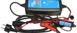
The use of batteries for autonomous power supply to homes is being developed. Wind generators and solar panels are combined into a common power grid, and the batteries are controlled using a PWM controller, for example, from WESWEN.
It is necessary to constantly monitor the performance of the batteries. This is what charge indicators are designed for. Simple devices simply monitor, and controllers control and manage battery recharging.
Homemade battery chargers
Assembling a charger for a car battery with your own hands is realistic and not particularly difficult. To do this, you need to have basic knowledge of electrical engineering and be able to hold a soldering iron in your hands.
Simple 6 and 12 V device
This scheme is the most basic and budget-friendly. Using this charger, you can efficiently charge any lead-acid battery with an operating voltage of 12 or 6 V and an electrical capacity of 10 to 120 A/h.
The device consists of a step-down transformer T1 and a powerful rectifier assembled using diodes VD2-VD5. The charging current is set by switches S2-S5, with the help of which quenching capacitors C1-C4 are connected to the power circuit of the primary winding of the transformer. Thanks to the multiple “weight” of each switch, various combinations allow you to stepwise adjust the charging current in the range of 1–15 A in 1 A increments. This is enough to select the optimal charging current.
For example, if a current of 5 A is required, then you will need to turn on the toggle switches S4 and S2. Closed S5, S3 and S2 will give a total of 11 A. To monitor the voltage on the battery, use a voltmeter PU1, the charging current is monitored using an ammeter PA1.
The design can use any power transformer with a power of about 300 W, including homemade ones. It should produce a voltage of 22–24 V on the secondary winding at a current of up to 10–15 A. In place of VD2-VD5, any rectifier diodes that can withstand a forward current of at least 10 A and a reverse voltage of at least 40 V are suitable. D214 or D242 are suitable. They should be installed through insulating gaskets on a radiator with a dissipation area of at least 300 cm2.
Capacitors C2-C5 must be non-polar paper with an operating voltage of at least 300 V. Suitable, for example, are MBChG, KBG-MN, MBGO, MBGP, MBM, MBGCh. Similar cube-shaped capacitors were widely used as phase-shifting capacitors for electric motors in household appliances. A DC voltmeter of type M5−2 with a measurement limit of 30 V was used as PU1. PA1 is an ammeter of the same type with a measurement limit of 30 A.
The circuit is simple, if you assemble it from serviceable parts, then it does not need adjustment. This device is also suitable for charging six-volt batteries, but the “weight” of each of the switches S2-S5 will be different. Therefore, you will have to navigate the charging currents using an ammeter.
With continuously adjustable current
Using this scheme, it is more difficult to assemble a charger for a car battery with your own hands, but it can be repeated and also does not contain scarce parts. With its help, it is possible to charge 12-volt batteries with a capacity of up to 120 A/h, the charge current is smoothly regulated.
The battery is charged using a pulsed current; a thyristor is used as a regulating element. In addition to the knob for smoothly adjusting the current, this design also has a mode switch, when turned on, the charging current doubles.
The charging mode is controlled visually using the RA1 dial gauge. Resistor R1 is homemade, made of nichrome or copper wire with a diameter of at least 0.8 mm. It serves as a current limiter. Lamp EL1 is an indicator lamp. In its place, any small-sized indicator lamp with a voltage of 24–36 V will do.
A step-down transformer can be used ready-made with an output voltage on the secondary winding of 18–24 V at a current of up to 15 A. If you don’t have a suitable device at hand, you can make it yourself from any network transformer with a power of 250–300 W. To do this, wind all windings from the transformer except the mains winding, and wind one secondary winding with any insulated wire with a cross-section of 6 mm. sq. The number of turns in the winding is 42.
Thyristor VD2 can be any of the KU202 series with the letters V-N. It is installed on a radiator with a dispersion area of at least 200 sq. cm. The power installation of the device is done with wires of minimal length and with a cross-section of at least 4 mm. sq. In place of VD1, any rectifier diode with a reverse voltage of at least 20 V and withstanding a current of at least 200 mA will work.
Setting up the device comes down to calibrating the RA1 ammeter. This can be done by connecting several 12-volt lamps with a total power of up to 250 W instead of a battery, monitoring the current using a known-good reference ammeter.
From a computer power supply
To assemble this simple charger with your own hands, you will need a regular power supply from an old ATX computer and knowledge of radio engineering. But the characteristics of the device will be decent. With its help, batteries are charged with a current of up to 10 A, adjusting the current and charge voltage. The only condition is that the power supply is desirable on the TL494 controller.
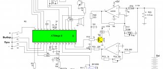
To create a car charger with your own hands from a computer power supply, you will have to assemble the circuit shown in the figure.
The step-by-step operations required for finalization will look like this:
- Bite off all the power bus wires, with the exception of the yellow and black ones.
- Connect the yellow and separately black wires together - these will be the “+” and “-” chargers, respectively (see diagram).
- Cut all traces leading to pins 1, 14, 15 and 16 of the TL494 controller.
- Install variable resistors with a nominal value of 10 and 4.4 kOhm on the power supply casing - these are the controls for regulating the voltage and charging current, respectively.
- Using a suspended installation, assemble the circuit shown in the figure above.