What is a thyristor for, its structure and operating principle?
A thyristor is a semiconductor device that has two states:
- open (passes current in one direction);
- closed (does not allow current to pass through).
This semiconductor device consists of 4 layers (regions) of semiconductor (in most cases, silicon) with different conductivity and has a pnpn structure.
Such a thyristor is called a dinistor (diode thyristor). Like a diode, it has two terminals and is triggered by a voltage of a certain level applied in the forward direction to the anode and cathode.
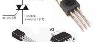
The more common triode thyristor is the thyristor. It has the same structure, but with an additional output - a control electrode (CE). All operations with the thyristor are performed using the UE.
There are also thyristors with two control electrodes, but they are less widespread.
Lecture 7.THYRISTORS
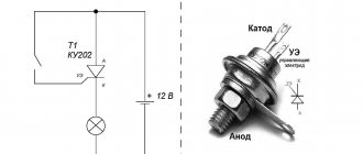
A thyristor is at least a four-layer semiconductor structure consisting of n -type and p -type semiconductors. The output from the external n -type conductor is called the cathode (K), the output from the external p p conductor is called the control electrode (CE). The structure of a semiconductor thyristor and its conventional graphic designation are shown in Fig. 1.
Classification of thyristors:
— on management
: uncontrollable, controlled;
- by locking
: non-lockable, lockable.
— by type (area of application)
: diode (dinistors), low-frequency, avalanche, high-frequency, high-speed, symmetrical, optocoupler, power modules.
Thyristor markings:
— developed after 1964:
consists of four elements: the first is a letter or number indicating the material (G or 1 - germanium, K or 2 - silicon); the second is a letter that determines controllability (N - uncontrollable, U - controlled; the third is a power group, the fourth is a type of this thyristor.
Thyristor markings:
— developed after 1979:
consists of five elements: the first is a letter indicating the type of device (D - diode, T - thyristor); the second is a letter defining the scope of application (C - triac, H - high-frequency,
B – high-speed, O – optocoupler, L – avalanche, M – power module), third – design size of three digits (the first digit is the serial number of the modification, the second digit is design size from 0 to 9, the third digit is design: 0 – unframed, 1 – pin with a flexible lead, 2 – pin with a rigid lead, 3 – tablet), fourth – rated current, fifth – voltage class.
An uncontrolled thyristor (dinistor) is a four-layer semiconductor structure shown in Fig. 1.
The current-voltage characteristic (CVC) of the dinistor is shown in Fig. 2. The current-voltage characteristic consists of two branches: the forward branch is located in the first quadrant, the reverse branch is located in the third quadrant.
Three characteristic sections can be distinguished on the direct branch of the current-voltage characteristic:
· Section 0A: 0 ≤ U ≤ Umax, I~0, dinistor closed.
· Section AB: U > Umax, 0 < I < Isp, the dinistor begins to open.
· BC section:: U0 ≤ U ≤ Umax, I > Isp, dinistor open.
On the reverse branch of the current-voltage characteristic two sections can be distinguished:
· Section 1: Upr < U < 0, I~0, dinistor closed.
· Section 2: U < Upr, I < 0, the dinistor current increases sharply, which is fraught with failure of the semiconductor structure.
Dinistors are used as relay elements in control and protection circuits, radiation receivers in optoelectronic pairs, and in automation devices.
The brands of some low-power dinistors are listed in Table 1.
Basic data of dinistors. Table 1.
| Brand | Maximum current, A | Maximum voltage, V | Forward voltage drop, V | Device type | Temperature range, 0С | frequency Hz |
| KN102I | 0,2 | 1,5 | Dinistor | -40…+60 | ||
| KN102Zh | 0,2 | 1,5 | Dinistor | -40…+60 |
An unturned thyristor (single-operation thyristor, thyristor) is a four-layer semiconductor structure shown in Fig. 3.
Under the influence of an external voltage, a semiconductor thyristor can be in two states: open (conducting), when the voltage is applied in the forward direction (plus on the anode, minus on the cathode), and the control voltage is applied to the control electrode (plus on the UE, minus on the cathode); and closed (non-conducting) when the voltage is applied in the opposite direction (plus at the cathode, minus at the anode). The current-voltage characteristic (CVC) of the thyristor is shown in Fig. 4. Currently, silicon is the main material for thyristors. The current-voltage characteristic has a forward branch (the thyristor is in a conducting state, where its resistance is about 1.0...1.5 Ohms) and a reverse branch (the thyristor is in a non-conducting state, where its resistance is hundreds of kOhms).
Conditions for the thyristor to be in a conducting state:
U0 ≤ U ≤ Umax and I > Isp.
Conditions for the thyristor to be in a locked state:
I < Isp or Upr < U < 0.
Thyristors, as well as rectifier diodes, are selected according to the average forward current Iav and permissible reverse voltage Urev = (0.6...0.7) Urev.
The brands of some thyristors are listed in Table 2.
Basic data of single-operation thyristors. Table 2.
| Brand | Maximum current, A | Maximum voltage, V | Forward voltage drop, V | Device type | Temperature range, 0С | frequency Hz |
| KU201L | and.thyristor | -60…+100 | ||||
| KU202N | and.thyristor | -25…+55 | ||||
| KU208G | and.thyristor | -55…+70 | ||||
| T112-16 | 100-1200 | 1,2 | n/h thyristor | -60…+125 | ||
| T253-1250 | 400-1200 | 1,0 | n/h thyristor | -60…+125 | ||
| MTT160 | 400-1600 | 1,1 | two thyristors | -60…+125 |
An example of a thyristor designation: T132-50-7 (50 is the average current in amperes, 7 is the maximum voltage in hundreds of volts).
A symmetrical thyristor (triac) is a double four-layer semiconductor structure shown in Fig. 5.
The current-voltage characteristic (CVC) of the triac is shown in Fig. 6. The current-voltage characteristic has the same shapes of the forward and reverse branches.
The brands of some triacs are listed in Table 3.
Basic data of triacs. Table 3.
| Brand | Maximum current, A | Maximum voltage, V | Forward voltage drop, V | Device type | Temperature range, 0С | frequency Hz |
| TS112-10 | 100-1200 | 1,3 | triac | -60…+125 | ||
| TS171-250 | 200-1200 | 0,8 | triac | -60…+110 |
An optical thyristor (optothyristor) is a semiconductor structure, shown in Fig. 7, which combines an LED and a luminous flux-controlled dinistor in one housing.
The current-voltage characteristic (volt-ampere characteristic) of an optothyristor is similar to the current-voltage characteristic of a single-operation thyristor (Fig. 4).
The brands of some optothyristors are listed in Table 4.
Basic data of optothyristors. Table 4.
| Brand | Maximum current, A | Maximum voltage, V | Forward voltage drop, V | Device type | Temperature range, 0С | frequency Hz |
| TO142-80 | 600-1200 | 1,1 | optothyristor | -40…+100 | ||
| MTOTO160 | 400-1600 | 1,1 | Pair of opto-thyristors | -50…+100 |
Special thyristors (high-speed, avalanche, thyristor diodes) are a group of power semiconductor devices with improved characteristics (see Table 5).
High-speed thyristors (TB)
have a turn-on time of no more than 4 μs and a turn-off time of no more than 63 μs.
Avalanche thyristors (TL)
have increased resistance to sudden increases in voltage and current through the thyristor.
Thyristor diodes (TD)
allow operation in the reverse direction as a diode.
Basic data of special thyristors. Table 5.
| Brand | Maximum current, A | Maximum voltage, V | Forward voltage drop, V | Device type | Temperature range, 0С | frequency Hz |
| TB151-50 | 500-1200 | 1,4 | b/d thyristor | -60…+125 | ||
| TL171-320 | 500-1100 | 0,9 | Avalanche thyristor | -60…+140 | ||
| TDCh153-400/160 | 400/160 | 600-1600 | 1,2 | Thyristor diode | -60…+125 |
Volt-ampere characteristics
The operating principle of a thyristor is clearly demonstrated by its current-voltage characteristic. It, like the characteristic of a conventional diode, is located in the I and III quadrants and consists of positive and negative branches. The negative branch is also similar to the diode branch and contains a section in which the device is locked - from zero to Ubreakdown. When the threshold voltage is reached, an avalanche breakdown occurs.
The positive branch requires careful consideration. If you apply direct voltage to the thyristor and begin to increase it, the current will grow slowly - the resistance of the closed semiconductor device is high. This is the red section of the graph. When a certain level is reached, the thyristor opens abruptly, its resistance decreases, the voltage drop also decreases, and the current increases - the blue section. This area is characterized by negative resistance, but the device behaves unstable here, with a pronounced tendency to transition to the open state.
Next, the thyristor enters the mode of a conventional diode - the green branch of the graph. This is how a diode thyristor works, and the ability to open when a certain level is reached is called the dinistor effect.
Types of thyristors, their differences and connection diagrams
Based on the two types considered, several more types of thyristors are produced. Each of them has its own scope of use.
Dinistors
The dinistor is connected to the circuit like a regular diode in series with the load. Nutrition can be constant or variable.
Symmetrical dinistors (bidirectional dinistors, diacs), which are two conventional devices connected back to back, also work in an alternating voltage circuit. They open from any half-wave of sinusoidal voltage. The current-voltage characteristic of the diac is symmetrical - the reverse branch is also located in the III quadrant and mirrors the direct one.
SCR
The most common type in this category of semiconductor devices. In a professional environment, triode thyristors are simply called thyristors, although this is fundamentally incorrect. The thyristor is also included in the circuit like a conventional diode (in a direct or alternating voltage circuit). Unlocking occurs when a positive voltage is applied to the UE (coincident in sign with the anode voltage during direct connection). In two-operation devices, locking is carried out by supplying the UE with a current in the opposite direction.
Triacs
Along with symmetrical dinistors, there are also symmetrical trinistors (triacs, triacs). They are two thyristors with common control, connected back-to-back and placed in one housing. If necessary, the triac can be replaced with two separate devices by connecting them according to the appropriate circuit.
The current-voltage characteristic of the triac is also symmetrical about zero.
Optothyristors
There are devices similar in structure and principle of operation to conventional thyristors, but which are unlocked by light incident on the open thyristor structure. If you combine such a switch and an LED controlled by an external signal source in one housing, you get a device called an optothyristor (thyristor optocoupler).
Thyristor protection
Thyristors are devices critical to the rate of rise of forward current diA/dt and forward voltage duAC/dt. Thyristors, like diodes, are characterized by the flow of reverse recovery current, a sharp drop of which to zero aggravates the possibility of overvoltages with a high duAC/dt value. Such overvoltages are a consequence of a sudden cessation of current in the inductive elements of the circuit, including small installation inductances. Therefore, to protect thyristors, various CFTP circuits are usually used, which in dynamic modes protect against unacceptable values of diA/dt and duAC/dt.
In most cases, the internal inductive reactance of the voltage sources included in the circuit of the switched-on thyristor turns out to be sufficient so as not to introduce additional inductance LS. Therefore, in practice, there is often a need for CFTPs that reduce the level and speed of overvoltages during shutdown (Fig. 7).
Rice. 7. Typical thyristor protection circuit
For this purpose, RC circuits connected in parallel with the thyristor are usually used. There are various circuit modifications of RC circuits and methods for calculating their parameters for different conditions of using thyristors.
For turn-off thyristors, switching trajectory formation circuits are used, similar in circuit design to CFTP transistors.
Source: School for Electrician
8465
Bookmarks
Comment 3
Latest publications
Experts from the National Research University "MPEI" discussed the future of engineering education at the Rosatom project session
July 30 at 13:35 28
IPPON at the video surveillance industry event Layta Connect in Kazan
July 29 at 17:27 27
Rockwell Automation presented a film episode about digital transformation with Technologies Added and Sustainder
July 28 at 23:42 37
The SME Corporation will launch a new “umbrella” guarantee mechanism for small businesses in August
July 28 at 23:40 34
"Samsung IT Academy" begins work at the Moscow Energy Institute
July 28 at 23:32 40
Schneider Electric Wins Project of the Year Award for Supply Chain Initiative
July 28 at 23:29 28
The manufacturer of specialized pipes invested 200 million rubles in the development of the enterprise with the support of PSB and the SME Corporation
July 27 at 18:18 44
Congratulations to the Bashkir Generating Company on its 15th anniversary
July 27 at 16:01 38
The unique experimental power plant of the National Research University "MPEI" received a positive conclusion from the state examination
July 27 at 14:44 71
A new point on the map of the Far Eastern projects of ZETO CJSC - a catering center for the seaport of Sukhodol
July 26 at 15:54 42
Comments 3
Oleg
A very convenient selection of materials for an essay on FOE. Thank you very much
June 21, 2014 at 16:11
Bookmarks
Comment is being verified
The text of the comment will be visible after verification by the administrator.
July 19 at 11:58
Bookmarks