How to reduce DC and AC voltage - an overview of methods
Effective ways to reduce DC and AC voltage. Find out how to lower the voltage from 220 to 110 or 36 Volts, or from 12 to 5 Volts.
According to the PUE, a voltage of no higher than 50 Volts should be used to power portable lighting, and when working in particularly dangerous and confined spaces - 12 Volts (PUE 6.1.16-18). In this case, power must be supplied through transformers. This is necessary in order to prevent electric shock. And the output parameters of power supplies or batteries do not always allow you to connect gadgets or other electronics. In connection with all this, we will talk about how to reduce the DC and AC voltage to the value you need. Content:
- Reducing AC voltage
- Connecting 110 V household appliances from the USA to a 220 V network
- We lower the voltage to power low-voltage lamps
- Reducing voltage in the house
- Ballast capacitor for powering low-power devices
- Reducing DC voltage
Voltage stabilization
You have learned how to lower the voltage to the desired level. Now it needs to be stabilized. For this purpose, special devices are used - zener diodes, which are made of semiconductor components. They are installed at the output of the DC power supply. The principle of operation is that a semiconductor is capable of passing a certain voltage, the excess is converted into heat and released through a radiator into the atmosphere. In other words, if the output of the power supply is 15 volts, and a 12 V stabilizer is installed, then it will pass exactly as much as needed. And the difference of 3 V will be used to heat the element (the law of conservation of energy applies).
Reducing DC voltage
When designing electronics, it is often necessary to reduce the voltage of the existing power supply. We will also look at several typical situations.
If you work with microcontrollers, you may have noticed that some of them operate on 3 Volts. Finding the right power supplies can be difficult, so you can use a phone charger. Then you need to lower its output from 5 to 3 Volts (3.3V). This can be done by lowering the output voltage of the power supply by replacing the zener diode in the feedback circuit. You can achieve any voltage, both high and low, by installing a zener diode of the desired rating. It can be determined by selection; in the diagram below it is highlighted with a red ellipse.
And on the board it looks like this:
In the next video, the author demonstrates such a modification, but not to reduce, but to increase the output parameters.
On chargers of a more advanced design, an adjustable zener diode TL431 is used, then adjustment is possible by replacing the resistor or the ratio of a pair of resistors, depending on the circuit design. They are marked in red in the diagram below.
In addition to replacing the zener diode on the charger board, you can lower the voltage using a resistor and a zener diode - this is called a parametric stabilizer.
Another option is to install a chain of diodes in the open circuit. Each silicon diode will drop about 0.6-0.7 Volts. So you can lower the voltage to the desired level by dialing the required number of diodes.
It often becomes necessary to connect the device to the vehicle’s on-board network; it ranges from 12 to 14.3-14.7 Volts. To lower the DC voltage from 12 to 9 Volts, you can use a linear stabilizer like L7809, and to lower it from 12 to 5 Volts, use L7805. Or their analogues ams1117-5.0 or ams1117-9.0 or amsr-7805-nz and similar for any desired voltage. The connection diagram for such stabilizers is shown below.
To power more powerful consumers, it is convenient to use pulse converters to reduce and regulate the voltage from the power source. An example of such devices are boards based on LM2596, and in English-language online stores they can be found by searching for “DC-DC step down” or “DC-DC buck converter”.
How to reduce voltage?
Due to the presence of a large number of international standards and technical solutions, electronic devices can be powered from various ratings. But not all of them are freely available, so to obtain the required potential difference you will have to use a converter. Such devices can be found both on the open market and assembled independently from radio components.
Due to the presence of two types of electric current: direct and alternating, the question of how to reduce the voltage should be considered in terms of each of them separately.
DC voltage reduction
In the practice of powering household appliances, there are many examples of electrical devices operating on direct current. But the operating voltage rating may differ significantly, for example, if you need to get 12 V from 36 V, or in situations where you need to power the device from the USB connector of a personal computer with 3 V instead of the existing 5 volts.
To reduce this level from a power supply or other source by almost half, you can use both simple methods - including additional resistance in the circuit, and more effective ones - replacing the voltage stabilizer in the feedback branch.
The figure above shows an example of a power supply circuit in which you can lower the voltage by changing the resistor and zener diode parameters. This node is circled in red in the figure, but in other models the installation location, as well as the connection method, may differ. In some circuits, you can use only one zener diode to lower the voltage.
If you do not have the ability to connect to a power supply, you can get by with less elegant methods. For example, you can lower the voltage by including a resistor in the circuit or select diodes; the second option is more practical for DC circuits. This principle is based on the voltage drop due to the internal resistance of the elements. Depending on the conductivity ratio of the workload and the semiconductor element, about 3 to 4 diodes may be needed.
The figure above shows a schematic diagram of voltage reduction using diodes. To do this, they are included in the circuit in series with respect to the load. In this case, the output voltage will be lower than the input voltage by exactly the same amount that will drop across each diode in the circuit. This is a fairly simple and affordable way to lower the voltage, but its main disadvantage is the power consumption for each diode, which will lead to additional energy costs.
How to reduce transformer voltage
How to reduce the voltage on a transformer.
In this article I will tell you how to make a transformer with a 12 V output from a transformer with a 32 V output. In other words, reduce the voltage of the transformer.
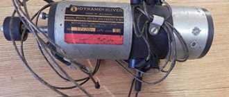
For example, I’ll take the trance from the Chinese b/w TV “Jinlipu”.
I think a lot of people have met him or similar.
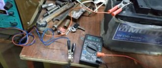
So, first we need to define the primary and secondary windings. To do this, you need a regular ohmmeter. We measure the resistance at the terminals of the transformer.
On the primary winding, the resistance is greater than on the secondary and is usually at least 85 ohms. Once we have identified these windings, we can begin to disassemble the transformer. It is necessary to separate the W-shaped plates from each other.
To do this, we will need some tools, namely: round nose pliers, pliers, a small screwdriver for “picking up” the plates, wire cutters, and a knife.
To pull out the very first record, you will have to work hard, but then the rest will go like clockwork.
You need to work very carefully, as you can easily cut yourself on the plates
On this particular transformer, we know that it has 32 V output.
In the case when we do not know this, we must measure the voltage before analysis, so that in the future we can calculate how many turns go to 1 V.
After the plates have been removed, you need to remove the plastic case from the windings. We do this boldly, since this will not affect the operation of the transformer in any way.
Then we find a contact on the secondary winding that is accessible for unwinding and use wire cutters to “bite it off” from the soldering point. Next, we begin to unwind the winding, and be sure to count the number of turns. To keep the wire out of the way, you can wrap it around a ruler or something similar.
Since this transformer has 3 terminals on the secondary winding (two extreme and one middle), it is logical to assume that the voltage at the middle terminal is 16V, exactly half of 32V. We unwind the winding to the middle contact, i.e. to half, and count the number of turns that we unwound.
(If the transformer has two terminals on the secondary winding, then unwind it “by eye” to half, count the turns while doing so, then cut off the unwound wire, strip its end, solder it back to the contact and assemble the transformer, doing everything the same as when disassembling, just in reverse order.
The number of turns you unwound is 105. This means 105 turns per 17V (35V-18V=17V). It follows that there are approximately 6.1 turns per 1B (105/17 = 6.176). Now, in order for us to reduce the voltage by another 6V (18V-12V=6V), you need to unwind approximately 36.6 turns (6.1*6=36.6). You can round this figure to 37.
To do this, you need to disassemble the transformer again and do this “procedure.”). In our case, having reached half of the winding, we got 106 turns. This means that these 106 turns are at 16V. We calculate how many turns there are per 1V (106/16=6.625) and unwind about 26.5 more turns (16V-12V=4V; 4V*6.625 turns=26.5 turns).
Then we “bite off” the unwound wire, strip the varnish from its end, tin it and solder it to the contact on the transformer from which it was “bitten off”.
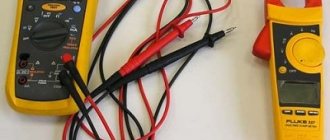
It remains to measure the voltage that we got:
Congratulations, colleagues, everything turned out great!
In the next article I will tell you how to make a 12V DC power supply from this transformer.
AC Voltage Undervoltage
An alternating voltage of 220 Volts is widely used for domestic needs; due to its physical characteristics, it is much easier to reduce it to any value or carry out any other manipulations. In most cases, electrical appliances are already designed to be powered from the electrical network, but if they were purchased abroad, then the voltage level for them may differ significantly.
For example, devices brought from the USA are powered by 110V AC, and some craftsmen undertake to rewind the step-down transformer to obtain the desired level. But it should be noted that the pulse converter, which is often included with various power tools and devices, should not be rewound, as this will lead to its incorrect operation in the future. It is much more advisable to install an autotransformer or another at the rating you need in order to lower the voltage.
Methods for reducing AC voltage
Alternating voltage, both high-voltage (at substations above 1000 Volts) and low-voltage (220 and 380 Volts) used in the power supply of residential and non-residential premises, can be reduced in two ways:
1. Transformer
. A transformer is an electromagnetic device made of a core (magnetic core) and inductively connected windings, the purpose of which is to convert the magnitude of alternating voltage without changing the frequency. Moreover, it is capable of changing the value both in the direction of decreasing and increasing.
At the same time, the transformer method is one of the most common, simple and safe, since due to galvanic isolation, that is, the absence of direct electrical contact between the windings, the probability of voltage from the primary side, in this case of a larger magnitude, reaching a device connected to the secondary is reduced to a minimum. (step-down winding of the transformer), protected by contactless communication.
It should be noted that there are so-called autotransformers that are capable of changing the voltage value at the terminals on the low side by rotating the handle.
2. The AC voltage reduced by a transformer can then be easily rectified using a diode or a diode assembly with a capacitor and a zener diode to improve the quality of the DC voltage.
3. Transformerless
. This method is used in inexpensive power supplies, mainly made in China, and consists of changing the magnitude of the alternating voltage due to the ballast capacitor. This method is used to power low-power electronics, such as LED lamps, charging flashlight batteries. The main disadvantage of transformerless ones is the high probability of the supply voltage (high) reaching the downward side as a result of the breakdown of capacitor C1.
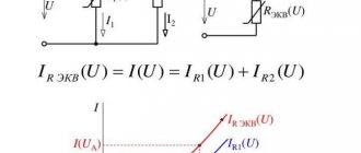
In any case, it is imperative to take into account not only the magnitude of the reduced voltage, but also the current strength of the secondary circuits, which is directly proportional to the power of the electrical equipment supplied.
Quenching capacitor instead of resistor
Sometimes the task arises of reducing the alternating voltage of a 220 volt network to a certain specified value, and the use of a step-down transformer (in this case) is not always advisable.
Let's say, a low-frequency step-down transformer, traditionally made on transformer hardware, capable of converting a power of 200 Watts, weighs more than a kilogram, not to mention the high cost.
Therefore, in some cases, it is possible to use a quenching resistor that will limit the current, but in this case, power will be released in the form of heat at the quenching resistor itself, and this is not always acceptable.
For example, if you need to power a 200 Watt lamp to only half its nominal value, you would need to dissipate 100 Watts of power into a quenching resistor, and this is an extremely dubious solution.
A very convenient alternative, for this example, can be the use of a quenching capacitor with a capacity of about 14 microfarads (this can be assembled from three metal film type K73-17, 4.7 microfarads each, designed for 250V, or better yet, 400V) this will allow you to obtain the required current without the need dissipate significant power as heat.
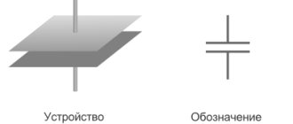
Let's consider the physical side of this solution. As is known, a capacitor connected to an alternating current circuit is a reactive element having capacitance associated with the frequency of the alternating current in the circuit, as well as with its own capacitance.
The greater the capacitance of the capacitor and the higher the frequency of the alternating voltage in the circuit, the greater the current passes through the capacitor, which means the capacitance of the capacitor is inversely proportional to its capacitance, as well as the frequency of the alternating current in the circuit where it is connected.
| This can also be seen from the formula for the capacitance of a capacitor: |
| If a resistor (resistive load) and a capacitor are connected in series to an alternating current circuit, then their total resistance can be found using the formula: |
| So, knowing the voltage at the load, the load current and the voltage at the quenching capacitor, you can determine the capacitance of the quenching capacitor, which must be connected in series with the load to obtain the required power parameters: |
| Consider an example: you need to power a 100-watt incandescent lamp rated at 110 volts from a 220-volt outlet. First of all, let's find the value of the lamp operating current: |
We obtain a lamp current value of 0.91 A. Now we can find the required value of the quenching capacitor capacitance, it will be equal to 15.2 μF.
It should be noted that this calculation is valid for a purely resistive load when the effective value occurs. When using a rectifier, it is necessary to take into account that the effective current value will be slightly less due to the action of ripples. It should also be remembered that polar capacitors should never be used as quenching capacitors.