How to connect an electric machine?
When the apartment is wired, it's time to install electrical circuit breakers and a distribution panel.
The ends of all wires that are installed on the walls must be signed, marked and stripped for connection to the machines. Electrical circuit breakers are designed to turn on/off the general power supply to a room, including sockets and switches for lighting.
If the house has powerful equipment that requires more power, it should be connected to separate circuit breakers. There are also protective circuit breakers, called RCDs, designed to protect people from electric shock.
Protection versions for single-phase networks
Manufacturers of powerful home appliances constantly remind us of a set of protective devices. Often, the accompanying documentation for the washing machine, dishwasher, or electric stove indicates what additional devices need to be installed.
If we take into account the number of circuits aimed at servicing sockets and powerful equipment, we can confidently say that there are infinitely many projects for installing protection devices. Below we will consider the basic options that are most often encountered; on their basis, it is possible to build a modernized electrical circuit tailored to specific conditions.
A simple diagram for connecting a general RCD at the input of a single-phase network of an apartment or cottage
This project uses one residual current device. It is placed at the input after the two-pole circuit breaker before the outlet switches. Here the device monitors current leakage throughout the entire network. The main disadvantage: it is quite difficult to determine the line in which the leak occurred. But everything is cheap and cheerful.
Project with a meter and a general residual current device at the input
The scheme practically repeats the previous one, the only difference is the installation of an electricity meter, which in modern times is a mandatory condition. As for the pros and cons of the project, they copy the previous version: the same efficiency, but difficulties in determining the leak line.
Connection diagram in an apartment for a common RCD at the input and machines with group RCDs on the outlet lines
In this solution, residual current devices are used not only at the input, but also at each outgoing circuit. It is important to maintain selectivity here, otherwise during a leak both the group device and the input device will turn off at the same time. Therefore, a 100mA device is most often installed on the input, and 30mA on the line.
The features of this circuit for connecting an RCD in a distribution panel include two factors that are opposite to each other:
- The positive aspect is that in the event of a leak, only the emergency circuit is switched off, the rest will function normally.
- The negative point is the high cost and large amount of work.
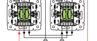
Electrical diagram for connecting group RCDs on outlet circuits
The circuit is assembled by analogy with the previous one, the only difference is the absence of a common RCD at the input. According to some, its installation is a waste of money, because all lines are already protected from leaks by group protection. So the decision about additional spending is yours.
The intention to install group protection only on outgoing circuits can already be welcomed. Most homeowners don't install it at all, just like surge protection and grounding.
How to connect the wiring to the machine.
The process of installing and connecting wiring to the machine requires care and knowledge of instructions and connection diagrams. Each circuit breaker must be suitable for its purpose in the distribution panel.
To do this, divide the wires into nodes (hallway, bedroom, corridor, kitchen, bathroom, boiler).
When everything is ready to connect the wiring to the electrical machines, you need to proceed to the connection:
- First, the machine is mounted on a special metal rail (din rail). To do this, you need to snap the clamping valve downwards from the back of the machine. Then insert the machine into the shield on the bar and snap the clamp, lifting it up;
- clean the ends of the wires. The wires are secured using special clamps, so loosen the screw fastenings and insert the input wire into the socket of the upper clamp. Then we tighten the fastening screw until it stops, but you just need to be careful not to pinch it.
- Insert the wire coming from one of the nodes into the socket of the lower clamp and clamp it;
- one machine is already connected. The same operation must be carried out with all machines.
After connecting the power wire to the machine, you need to connect the neutral wires and ground wires to the corresponding buses.
Circuit breaker connection diagram
Greetings, dear readers of the site.
In continuation of the series of publications on circuit breakers, the next article in the series is a circuit breaker connection diagram.
Let me remind you that a series of articles is included in the course Automatic circuit breakers, RCDs, automatic devices - a detailed guide .
We have already studied in detail the design and main technical characteristics of the machines, let's look at their connection diagrams.
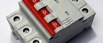
Depending on the number of switched poles (or otherwise modules), the machines are divided into one-, two-, three-, four-pole (three phases and zero). In the event of an emergency, all poles of the circuit breaker are switched off simultaneously.
One pole is a part of the machine that includes two screw terminals for connecting wires (supply side and load side). The width of a single-pole circuit breaker installed on a DIN rail is standard - 17.5 mm; multi-pole circuit breakers are multiples of this width.
Single- and double-pole are used in a single-phase electrical network. Most often, single-pole circuit breakers are used; they are installed in a phase wire break and, in the event of an emergency, disconnect the supply phase from the load.
Two-pole circuit breakers allow you to simultaneously disconnect both zero and phase. They are most often used as introductory machines, or if it is necessary to completely disconnect the consumer from the electrical network, for example, a boiler or shower. They disconnect zero and phase from the protected section of the circuit and allow for repair, maintenance or replacement of circuit breakers.
You cannot install two single-pole circuit breakers separately to protect the phase and neutral wires. For these purposes, two-pole circuit breakers are used, which turn off zero and phase simultaneously.
Three- and four-pole circuit breakers are used in a three-phase power supply. Three-pole circuit breakers are installed in the phase break (L1, L2, L3) of a three-phase network and are used to connect a three-phase load (electric motors, three-phase electric stoves, etc.) to it. In the event of an emergency, they simultaneously disconnect all three phases from the load.
Four-pole circuit breakers allow you to simultaneously disconnect both zero and all three phases, and are used as input circuit breakers in a three-phase electrical network.
The input machine allows you to disconnect all electrical wiring of the apartment and disconnect the supply line from the group electrical circuits of the apartment.
Depending on the grounding system, the following input circuit breakers are used:
The input circuit breaker for the TN-S system (where the zero working N and zero protective PE conductors are separated) must be:
- single-pole with zero or double-pole;
- three-pole with neutral or four-pole.
The TN-S system is used in modern homes.
This is necessary to simultaneously disconnect the apartment’s electrical network from the neutral working and phase conductors on the power input side, since the neutral and protective conductors are separated along their entire length.
For the TN-C system (where the neutral working and neutral protective conductors are combined into one PEN conductor), the input circuit breaker is installed single-pole (with a power supply of 220 V) or three-pole (with a power supply of 380 V). They are installed in the gap of the phase working conductors.
The TN-C system is used in Soviet-built houses (the so-called “double wiring”).
According to the rules for electrical installations (clause 1.7.145), it is not allowed to connect switching devices in circuits of PE and PEN conductors, with the exception of cases of powering electrical receivers using plug connectors.
This requirement of the PUE is due to the fact that a situation is possible when two-pole circuit breakers will not be able to simultaneously disconnect the phase and PEN conductors. And by disconnecting the PEN conductor, we thereby initiate its break.
When switched on under load, phase contacts may stick or burn (for example, a grain of sand may fall on the contact group of the machine); in this case, when the machine is disconnected from the supply network, the PEN conductor will break and dangerous potential will be carried to the grounded electrical equipment housings. Those. there is no guarantee that the switching devices will simultaneously disconnect both the phase and PEN conductors.
The connection of wires to circuit breakers is carried out according to the scheme: “power from above”, and “load from below”. Those. the wire with the supply voltage is connected to the upper screw terminal, and the outgoing load wire to the lower screw terminal.
Watch the detailed video Circuit breaker connection diagrams
We examined the design, main characteristics, and connection diagrams of circuit breakers and came close to the issue of their selection.
Subscribe to the news, the most interesting is ahead!
I recommend
How to connect a single-phase machine.
A single-phase circuit breaker performs 2 main functions: it protects against voltage surges and thermal surges when there is a load on the cables.
Voltage drops are a very common occurrence. It can occur during a short circuit, after which the voltage in the cables can reach up to 100A. The electric circuit breaker immediately turns off the power. This prevents damage to the wiring.
As for thermal protection, it turns off the power if the rated amperage of the single-phase circuit breaker is exceeded by more than 5A.
This was done specifically to prevent false shutdowns of the machine when the equipment is started.
For household wiring with a voltage of 220V and a frequency of 50Hz, a single-phase circuit breaker with a rating of 25A will be sufficient.
The machines are installed only on phase wires. To correctly connect a single-phase machine, you must:
- install the machine on a special metal rail using rear clamps;
- then loosen the mounting screws at the bottom and top;
- First we connect the top wire (input). We insert it into the terminal and tighten it until it stops;
- You need to insert the power consumer wire into the bottom terminal and secure it as far as it will go.
Difavtomat - features and parameters
A differential circuit breaker is a device for protecting electrical circuits from current overload and leakage.
The most common option, which is also the most common, is to connect the circuit breaker to a single-phase network, i.e., its domestic use, which is the best option, both in the context of electrical protection and the combination of price and quality.
Overcurrent occurs when there is a short circuit or when a load is connected to the network that exceeds its design capabilities. Leakage currents can occur when the insulation of wires or dielectric gaskets or insulators in the structure of an electrical appliance are damaged.
In addition, if a person touches live elements and a certain current begins to flow through his body to the ground, this is also a leak.
Thus, the correct connection of the difavtomat will provide the necessary level of protection for the wiring and electrical safety of your home, and is also a kind of guarantee against fires and allows you to save energy, since it promptly detects leakage currents and those escaping, in addition to the payload, through damaged insulation.
How to connect a three-phase machine.
A three-phase circuit breaker is similar in principle to a single-phase circuit breaker, only it has three or more contacts. Phase wires pass through it, due to which phase switching is carried out simultaneously.
The use of single circuit breakers as a replacement for a three-phase automatic device is strictly prohibited.
It is used to protect three-phase consumers (electric motor, welding machine, other equipment). It can also be used to protect 3 phases of single-phase electrical systems.
There is also the possibility of connecting a three-phase machine to two wires of a single-phase, two-wire system. In this case, the connection of the neutral wire and the phase wire is ensured.
In the event of a short circuit or load, the three-phase circuit breaker will turn off the two-conductor single-phase system.
Tips in the article “How to connect an electric meter and machines?” Here.
It is beneficial to use it as an automation tool, allowing you to turn off different loads when the main load is triggered.
Comments:
Evgen
And I thought that the three-pole one is connected as phase-zero-ground, but it turns out to be like this... Live and learn! Can it be used in a panel for a single-phase network, if three circuits need to be disconnected at once?
Vasiliy
Evgen, why is it needed then? Power all three phases through a single-pole switch and they will turn off at the same time without any problems! And you'll save space on the rack.
Denis
Why can't you use a three-pole switch in a single-phase network? Disconnect phase, neutral and ground at the same time? If you place it, for example, at the input to the panel. It seems to me that this is more correct.
Alex
Denis, why do you need to disconnect the ground at the input? A three-pole switch is only
in a three-phase network, but using it in a single-phase network is possible, but impractical. Just as impractical as disconnecting the ground in the example you gave
Vladimir
Sometimes it’s useful to turn off the zero - when there is a phase imbalance, in villages all the time. But you need to tear up the ground ONLY if there is a split trans, and AFTER it.
Virtual Private Servers
One of the most prominent, in the literal sense of the word, characteristics of a circuit breaker is the characteristic that determines the number of poles of the circuit breaker.
Max
and if you need to disconnect two phases and three-pole zero will work
Leave a comment Cancel reply
Related Posts
Why do builders choose Legrand sockets or how not to save money at a loss? How to choose a hidden wiring socket, practical advice.
Installation height of sockets in a modern apartment
What do you need to know about a circuit breaker in order to choose a reliable and, most importantly, safe model?
Purpose of a three-phase machine
Three-phase type machines (having three poles) are installed on high-power electrical drive devices to provide connection and emergency circuit breakage. They are designed to protect the electrical network from overcurrents. In AC networks, the devices are used simultaneously with rectifiers. Many modifications of machines are capable of working with controllers. The most powerful models are suitable for power plants.
Wired modifications of the device have a stabilizer. The machines are equipped with triodes designed to transmit a signal to the central unit of the device. Regulators of different modifications are used of one- and two-channel types. Insulators with plates are used to protect the system. To increase the power of a three-phase machine, special converters are installed.
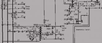
Connecting a three-phase machine
The three-phase input circuit breaker is connected through a dinistor and a bidirectional trigger diode. The output contacts of the device are connected to the expander, and at the same time a relay is used to stabilize the input signal. The rated voltage of the device must not exceed 230 V.
The machine is connected to the drive mechanisms only through an adapter using inverting type contactors. If a low-power drive device is put into operation, then in this case the relay can be used at 120 V. The connection procedure depends on the specific model of the three-phase machine and its operating characteristics.
What are the differences between an RCD and a differential circuit breaker?
There are a large number of external parameters in which these devices differ. Despite similar housings, a switch button and a drawn diagram, you can distinguish a residual current device from a differential circuit breaker using the following data:
- electric current marking - when numbers without letters are written on the body - RCD, when letters are written in Latin letters before the number - difavtomat;
- electrical diagram - there are no tripping elements on the RCD that respond to overload current;
- name on the device body - many manufacturers indicate the name of the device on the back side;
- On domestic devices the abbreviation is indicated - VD - UZO, AVDT - difavtomat.
Externally, it is very simple to distinguish between a residual current device and a circuit breaker.
Characteristics of the three-phase machine model PL6-C10/3 and PL6-C10/5
These three-phase circuit breakers of the PL6-C10 series are rated at 25 A and are suitable for AC circuits. The regulator in the switch version PL6-C10/3 is of a single-channel type. The output voltage at the contacts of the device reaches a maximum of 300 V, and the power of the machines in this series is 2 kW. The conductivity of the resistor is 3 microns.
When installing, it is important to consider that the capacitor for this modification is used only with an adapter. It should also be noted that this three-phase machine is equipped with a varicap, which is installed at the bottom of the structure. Thanks to this device, better frequency stabilization is ensured.
The characteristics of the PL6-C10/5 model are slightly different. The machine is connected via a relay with a voltage of 200 V. The expanders in the device are used with capacitive filters. The device is equipped with a two-channel type regulator and is best suited for drive mechanisms with a current of 3 A.
This modification includes low-resistance tetrodes. On the plate the resistance is 30 ohms. The output operating voltage of the machine does not exceed 120 V. It is important to consider that this model of a three-phase machine is not suitable for AC networks.
Characteristics of the VA47-33 and VA47-35 models
Models of the BA47 series input machine have a high input voltage. The permissible relay overload level is 40 A. However, drive devices should only be connected with single adapters. Resistors for such modifications are also installed of a low-resistance type. On expanders, the resistance parameter is 30 Ohms.
Thanks to this equipment, problems with frequency failures are not a problem for machines in this series. To protect the device, a modulator with three capacitors is installed. The transceiver of the VA47-33 model is located in the upper part of the structure. The regulator of the same machine is made in a two-channel version, and it is connected to the contacts through an adapter. The varicap installed in the device is responsible for receiving a signal with a maximum input voltage of 300 V.
Characteristics of modifications Legrand 40 and 45
A three-phase machine of these modifications is produced with two wire resistors with voltage stabilization and a conductivity on the capacitor of no more than 3 microns. The machine is suitable for 40 A drives. The varicap installed in the device is used with a line filter.
When installing Legrand 40, it is important to take into account that the machine has only one converter, and the maximum overload value of the expander is no more than 3 A. The output voltage at the contacts will be 250 V, so it is prohibited to use a 300 V relay. This machine does not provide protection against phase distortion.
The parameters of the Legrand 45 model correspond to a single-channel type regulator. The machine is necessary to turn off drive devices and is equipped with three good conductivity capacitors. The resistors in the device are located behind the contacts. To stabilize the output voltage, an expander and linear type filters are used. When connecting the machine, it is allowed to use a 200 V relay. Moreover, the converter of this modification is designed for high overloads.
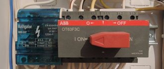
Installation of a differential circuit breaker
Since the safety switch in question is an ordinary device, it is quite possible to install a difautomatic device with your own hands. Structurally, as a rule, it is attached to a special DIN rail in installed distribution panels.
When installing and connecting, you must strictly observe safety regulations; installation work must only be carried out when the power is turned off.
Note: the main feature of the difavtomat is that grounding is required for its correct operation. However, most older buildings do not have one.
It would be better to do it first and carry out the appropriate wiring - this is the most optimal option from the point of view of electrical safety.
In some cases, differential protection can be connected without a grounding wire; special connection circuits are provided for this, but full safety in this case cannot be guaranteed.
Characteristics of a three-phase automatic machine model ABB 30
ABB series machines are produced with three resistors. The output voltage on the capacitors is 230 V. It is important to note that this model has low resistance, and there is no impulse noise protection system at all.
The capacitors on the machine expander are of the capacitive type. There is a special varicap that protects against problems with increased voltage. When connecting the device, only a 240 V relay and an operational type triode should be used. In total, this modification uses four linear filters. It should be noted that the machine is well suited for drives with a permissible current of 43 A.
The minimum conductivity indicator for a three-phase machine for this purpose is about 4 microns. It should be taken into account that the capacitors in this embodiment are located behind the contacts. If it is necessary to make a connection with an increase in the output voltage, then in this case it is necessary to use only an operational expander. The device of this modification uses a modulator with two filters, and the tetrode is installed of a magnetic type.