Modern three-phase meters, which were previously used exclusively in the industrial sector, have recently often been used for domestic purposes. This is explained by the fact that owners of private houses increasingly prefer to use three-phase electrical networks, in which the installation of special power equipment (induction motors, powerful pumps, etc.) is allowed.
Meter connection diagram
The general diagram for connecting an electric meter, which is installed in power lines, can be found in the figure above.
On the other hand, the connection of a three-phase meter to household energy supply networks is explained by increased consumer power, which single-phase circuits cannot provide.
But before the user tries to take advantage of the benefits of this device, he needs to thoroughly understand how to properly connect a 3-phase meter to an existing electrical network.
The need for three-phase metering
According to the requirements of current regulations, when the amount of power consumed by an object increases to 15-20 kW and above, a three-phase power system must be used. This is explained by the fact that at the indicated powers, the amount of electric current in the circuits can reach 70 Amperes, which is considered unacceptable for city apartments.
Additional Information. To ensure normal operation of a multi-apartment network, you will need an electrical cable with a core cross-section of about 10 mm², the installation of which is practically impossible in real conditions.
At these consumption rates, the current provisions of the PUE require the use of a power supply system designed for 380 Volts. Accounting for consumed energy in this case is ensured by connecting a three-phase electric meter directly to the supply circuit.
The power consumed in this case is distributed between three phase conductors, as a result of which the current in each of them is reduced to approximately 2.5 Amperes. Thanks to this approach, the cross-section of the conductors of the supply cable to which the entire electrical network is connected can be reduced to a value of about 2.5 mm².
The dependence of the cross-section of conductors on the current flowing through them or on the power consumed by the load is presented in a separate table (see https://elquanta.ru/schetchiki/podklyuchenie-schetchika.html). It is clear that when this parameter is reduced, the cost of all electrical wiring also decreases, and its installation is also significantly simplified.
The transition to a modern and universal three-phase power supply circuit is also preferable from the point of view of maintaining the required temperature balance, ensuring safe operating conditions for the entire power supply system.
Naturally, this method of organizing power supply and accounting in a private home will require significant material costs. So everyone who wants to take advantage of a three-phase connection needs to determine their financial capabilities in advance.
How to connect an electric meter through current transformers?
There are several schemes for such connection. Let's analyze all these schemes in relation to the three-phase connection option. What are electricity meters for? In general, meters are needed in order to take into account the electrical energy consumed in three- and four-wire networks with a current frequency of 50 hertz. Three-phase type meters are of the following types:
- 3*57.7/100 V;
- 3*230/400 V.
Such meters must be connected to a source of electricity using measuring current transformers designed for a secondary current of 5 A and voltage transformers with a secondary voltage of 100 V.
The circuits discussed here are applicable to any type of meters (both induction-type devices and electronic ones).
The first thing to remember when making a connection is that when connecting, it is necessary to observe the polarity of the connection of the windings (L1, L2 - primary; I1, I2 - secondary) of the current transformers. The polarity of the windings of voltage transformers is also subject to mandatory rechecking. The transformers themselves also need to be chosen correctly.
About the principles of connection using current transformers
Let's start looking at connection diagrams with meters that have semi-indirect connection. There are several such schemes.
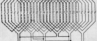
Ten-wire
In this circuit, the power circuits are separated by current and voltage, which is a significant advantage for reasons of electrical safety.
The negative side of this scheme is that you need a lot of wires to connect.
Now let's look at the purpose of the existing clamps:
- Input wire clamp for phase A;
- Clamp of the input wire of the measuring winding of phase A;
- Output wire clamp for phase A;
- Phase B input wire clamp;
- Clamp of the input wire of the measuring winding of phase B;
- Output wire clamp for phase B;
- Input wire clamp for phase C;
- Clamp of the input wire of the measuring winding phase C;
- Output wire clamp for phase C;
- Input neutral wire clamp;
- Neutral wire clamp.
Current transformer contacts:
- L1 – phase (power) line input contact;
- L2 – phase line output contact (load);
- I1 – measurement winding input contact;
- I2 – measurement winding output contact.
Here is a description of the diagram of such a connection.
Current transformers must be connected to the phase wires with terminals L1 and L2.
Phase A is connected to terminal L1 of current transformer TT1, and terminal 2 of the meter is also connected there. Terminal 1 is connected to pin I1 of CT1.
Contacts I2 of current transformers TT1 and TT2 must be connected together, contacts 6 and 10 of the meter are connected to the same point, after which all this must be connected to the neutral.
Contacts L2 of all CTs are connected to the load. Now let's look at connecting the remaining contacts:
- Contact 3 of the meter is connected to I2 TT1;
- Contact 4 of the counter – I1 TT2;
- Contact 5 of the counter – phase B input and terminal L1 of TT2;
- Contact 7 of the counter – terminal I1 TT3;
- Contact 8 of the counter – phase C input and terminal L1 of TT3;
- Contact 9 of the counter – terminal I2 TT3.
Connecting current transformers in a star configuration
In such a scheme, fewer wires are needed to make the connection. In this circuit, terminals I2 of all current transformers, connected together, are connected to terminal 11 of the meter. Contacts 3, 6, 9 and 10, connected together, are connected to the neutral wire. We connect the remaining terminals in the same way as in the previous version.
Connection diagram using test terminal box
There is a special requirement for connecting electricity meters through transformers (PUE, Chapter 1.5, Section 1.5.23), which means that this connection must be made using a test block (box).
The presence of such a box (block) makes it possible to short-circuit the secondary windings of current transformers, connect a reference (model) meter without disconnecting the load, and change meters by disconnecting all circuits in the test box.
We will ignore only one circuit - a seven-wire circuit (otherwise called a circuit that has combined voltage and current circuits). We do not consider it for the reason that such a scheme is outdated.
Its significant disadvantage is that it has a galvanic type connection between the input and output circuits, and this is a source of considerable danger for those who will service electricity meters.
So we have examined all existing schemes for connecting electric meters using current transformers. Which one to use is an individual matter for everyone. The only thing that needs to be taken into account is the individual characteristics of the location where the device is to be installed and do not forget about the requirements of the special rules of the Electrical Installation Code.
Types of connection
Depending on the method of switching on a three-phase device, the following types of connection are distinguished:
- The so-called “direct” or immediate;
- Semi-indirect;
- Indirect.
Connecting a three-phase meter via current transformers
The first of them is used in cases where the current in each phase does not exceed 100A. With this approach, the lead wires are connected directly to the device contacts.
In this case, a direct connection meter allows you to implement the simplest of all possible solutions, which does not require significant material costs. In contrast, the other two options involve the use of special converting devices that make it possible to reduce the current in the controlled circuits.
Additional information. In order to connect a three-phase meter to an existing network with a current in each of the lines of more than 100 Amps, current transformers (CTs) will be required.
Let's consider various schemes for switching on an electric meter using the example of specific samples of metering devices.
Direct
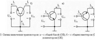
This type of connection, as applied to devices from, for example, is practically no different from a typical single-phase meter connection circuit. The current consumed by the load passes in this case directly through the winding of the device connected to the open circuit of the supply circuit.
The electrical diagram for connecting three-phase meters directly looks like this (see the figure below).
Direct activation
Important! A three-phase meter installed on site can be switched on directly only when the power dissipated in the load does not exceed 60 kW.
For high values of this parameter, current regulations require the use of semi-indirect or indirect inclusions.
Semi-indirect and indirect methods
With this method, the electricity meter in all three phases is switched on through a special step-down device called a current transformer. Its use makes it possible to organize the metering procedure in circuits with significant currents and dissipated powers (the diagram is given below).
Connection diagram via CT
In the above figure, L1 and L2 are the designations of the inputs and outputs of each of the three phases, and I1 and I2 are the corresponding measuring windings, which are connected to the break in the supply phase circuits.
A significant disadvantage of this switching method is that it is mandatory to take into account the transformation coefficient, which affects the results of the assessment of consumed electricity, as well as the calculation of the payment amount. Another inconvenience of transformer connection is the difficulty of taking readings, which only representatives of energy companies are authorized to do.
A three-phase metering device of indirect and semi-indirect type is used extremely rarely in private country farms. Their main area of application is high-voltage lines for general industrial purposes, with an effective voltage of 6 (10) kV.
Connecting a three-phase semi-indirect meter
These devices are connected to the network through current transformers, making it possible to use them in networks with fairly high powers (up to 60 kW). Using this accounting method, to determine the flow rate, you need to multiply the difference in readings by the set transformation ratio.
There are several types of connection for semi-indirect connection meters.
1 Star connection of current transformers
The process of connecting wires looks like this:
- contacts 3, 6, 9, 10 – are closed and connected to the neutral wire;
- contacts I2 - closed, connected to terminal 11;
- 1 – to I1 phase A;
- 4 – to I1 phase B;
- 7 – to I1 phase C;
- 2 – to L1 phase A;
- 5 – to L1 phase B;
- 8 – to L1 phase C.
Figure - Star connection diagram
Connecting a three-phase indirect meter
These devices are designed to perform electricity metering at high-voltage connections (6-10 kV and more), the connection is realized using voltage and current transformers.
Below are the main diagrams for connecting three-phase meters via current and voltage transformers:
1) Scheme for connecting a three-element meter to a four-wire network with a grounded neutral: (figure below)
2) Scheme for connecting a three-element meter to a four-wire network. Three current transformers, direct connection to voltage:(picture below)
3) Scheme for connecting a three-element meter to a three-wire line - two current transformers, three voltage transformers: (figure below)
When connecting a three-element meter according to scheme No. 3:
- phase B current is calculated with the subtraction of the zero-sequence current;
- direct, negative and zero sequence currents of the fundamental frequency are not used (symmetrical components);
- active and reactive power in phase B are calculated by subtracting the zero-sequence current from the phase current;
- Electrical energy accounting is carried out taking into account the above comments.
4) Scheme for connecting a two-element meter to a three-wire line - two current transformers, two voltage transformers (figure below)
When connecting the meter according to schemes No. 4 and No. 5:
- The zero sequence voltage of the fundamental frequency is not measured (symmetrical components);
- direct, negative and zero sequence currents of the fundamental frequency (symmetrical components) are not measured;
- connection capacities are calculated using formulas;
- Electrical energy accounting is carried out taking into account the above comments.
5) Connection diagram of a two-element meter to a three-wire line - two current transformers, direct voltage connection (figure below)
Attention!: The possibility of connecting according to a specific scheme must be indicated in the passport or manual for a specific type of meter. {SOURCE}
{SOURCE}
Induction devices
Connecting the meter via current transformers
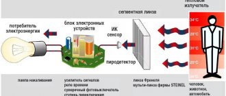
The operating procedure of electricity meters of this class is based on the rotation of the working disk under the influence of an alternating electric field generated by the measured current.
In the figure below you can see a schematic representation of the simplest example of the “Energomer” type (a three-phase product works on the same principle).
Internal counter mechanism
In this diagram, 1 means a current coil through which a load current flows, creating in it a magnetic flux Fi of corresponding magnitude. The field that appears in this case penetrates the aluminum disk with its lines of force and induces eddy currents in it.
These currents form another field formation, which begins to interact with the field Фu of the voltage coil (it is designated as “2”). The interaction of these two structures produces a pulsed torque that drives the aluminum disk.
The latter, through a worm gear, drives the mechanical counting unit 3. The permanent magnet 4 is necessary to form a braking effect that ensures stabilization of the rotation of the disk.
Electronic devices
Three-phase meter: selection, installation, connection
Modern electronic electricity metering is organized according to a slightly different principle and allows you to obtain a number of advantages, the main of which are:
- High accuracy of readings, significantly exceeding the same indicator for an induction device;
- Possibility of operation in multi-tariff mode;
- Permissibility of organizing automatic readings.
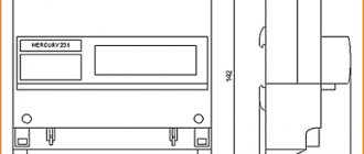
A three-phase electronic meter works on the principle of counting the number of pulses generated by an electronic device built into it, the repetition frequency of which depends on the magnitude of the flowing current (its appearance is shown below).
Appearance of the electronic device
Before connecting a three-phase meter in one way or another, you must become familiar with the conditions under which, according to current regulations, its installation is permitted.
According to the basic provisions of the PUE, modern three-phase electronic devices are connected to the network according to circuits that are also suitable for induction devices. On the contact panel of the electronic device, the input and output contacts are placed in exactly the same way as on all other types of three-phase meters.
Types of inclusions and their features
Depending on the method of switching the windings of current transformers, three-phase meters installed in electrical networks are connected according to the following schemes:
- direct connection;
- indirect inclusion;
- semi-indirect connection.
Direct inclusion is called direct inclusion, and to understand the differences between the second and third types, it is necessary to take into account the scope of their application. Purely indirect connection is the open installation of current transformers (CTs) on high-voltage power cables of a three-phase line (6-10 kV). This method is found only at power substations and at large industrial enterprises with their own power distribution networks. In domestic conditions, this type of connection of transformers is not used.
Protective and transition devices
Any three-phase electricity meter connected to high-voltage networks through current transformers must be protected from overvoltages that often occur in power supply lines. For this purpose, special devices are installed in series with it to limit the voltages that arise in the line in an emergency. They are found under various names, the most common of which is oin.
This device, in its functionality, resembles a circuit breaker. But it is not triggered by overcurrent, but is used as a voltage limiter on the section of the supply line into which the three-phase meter is connected.
Below is a diagram according to which this device is installed in the circuit of the equipment it protects.
Connection diagram for SPP (SPD)
Before installing a three-phase meter in the supply circuit, experts advise using another special device connected to the terminal block of the meter itself.
The indicated product, found under the designation IKK, has in its design a number of jumpers that allow you to switch the connection in a user-friendly way. The appearance of this device and the diagram for connecting it to the power circuit are shown in the photo below.
Transitional terminal block
From this photo it is clear that when using IKK, the installation and dismantling of any type of metering device is significantly simplified, which is very convenient when carrying out their repair, for example.
Additional Information. If necessary, such a panel can be used to connect external measuring instruments.
Additional installation of the IKK is carried out by connecting it in parallel to an existing terminal block.
In the final part of the review, we note that the previously discussed meter switching schemes are selected depending on their operating conditions and the nature of the existing electrical network. To organize their correct connection, it is important to take into account all the factors that affect the performance of a particular counting device, determined not only by its class, but also by the features of the reading-taking mechanism.
Connecting a three-phase semi-indirect meter
These devices are connected to the network through current transformers, making it possible to use them in networks with fairly high powers (up to 60 kW). Using this accounting method, to determine the flow rate, you need to multiply the difference in readings by the set transformation ratio.
There are several types of connection for semi-indirect connection meters.
1 Star connection of current transformers
The process of connecting wires looks like this:
- contacts 3, 6, 9, 10 – are closed and connected to the neutral wire;
- contacts I2 - closed, connected to terminal 11;
- 1 – to I1 phase A;
- 4 – to I1 phase B;
- 7 – to I1 phase C;
- 2 – to L1 phase A;
- 5 – to L1 phase B;
- 8 – to L1 phase C.
Figure - Star connection diagram
Ten-wire circuit for switching on the meter
10-wire circuit
This circuit is characterized by improved electrical safety, due to the isolation of current and voltage circuits from each other.
Connecting a three-phase indirect meter
These devices are designed to perform electricity metering at high-voltage connections (6-10 kV and more), the connection is realized using voltage and current transformers.
Below are the main diagrams for connecting three-phase meters via current and voltage transformers:
1) Scheme for connecting a three-element meter to a four-wire network with a grounded neutral: (figure below) 2) Scheme for connecting a three-element meter to a four-wire network. Three current transformers, direct connection to voltage: (figure below) 3) Connection diagram of a three-element meter to a three-wire line - two current transformers, three voltage transformers: (figure below)
When connecting a three-element meter according to scheme No. 3:
- phase B current is calculated with the subtraction of the zero-sequence current;
- direct, negative and zero sequence currents of the fundamental frequency are not used (symmetrical components);
- active and reactive power in phase B are calculated by subtracting the zero-sequence current from the phase current;
- Electrical energy accounting is carried out taking into account the above comments.
4) Scheme for connecting a two-element meter to a three-wire line - two current transformers, two voltage transformers (figure below)
When connecting the meter according to schemes No. 4 and No. 5:
- The zero sequence voltage of the fundamental frequency is not measured (symmetrical components);
- direct, negative and zero sequence currents of the fundamental frequency (symmetrical components) are not measured;
- connection capacities are calculated using formulas;
- Electrical energy accounting is carried out taking into account the above comments.
5) Connection diagram of a two-element meter to a three-wire line - two current transformers, direct voltage connection (figure below)
Attention!: The possibility of connecting according to a specific scheme must be indicated in the passport or manual for a specific type of meter. Direct connection three-phase meter Energomera
Direct connection three-phase meter Energomera
Today's article is devoted to disassembling the direct connection meter Energomer TsE 6803V. Let me remind you that I already have a similar article about the design of a single-phase Energomer meter. There is also information on how the meter counts electricity.
This time – not one, but three phases!
For those who are more deeply interested in the topic, I have already written in detail in another article how the three phases differ from one.
I have another popular article on such meters - about connecting and installing three-phase meters. It contains very detailed instructions on how to secure and connect such meters.
I came across a three-phase meter that has been taken out of service. We'll take it apart down to the screw, get ready!