How to repair an electric soldering iron
An electric soldering iron is a well-known heating device designed for joining a wide variety of parts made of non-ferrous or ferrous metals.
The operating principle of the tool is based on the heating effect of its working tip (tip), which melts the solder with flux. The resulting liquid mixture fills all the unevenness and voids between the parts and forms a reliable connection after cooling.
But during operation, the tool can break, and such damage manifests itself in a variety of forms. That is why independent repair of a soldering iron is a mandatory operation that any master working with it must master.
Main details
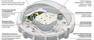
In order to quickly and efficiently repair an electric soldering iron with your own hands, first of all, you need to familiarize yourself with its design, which includes the following components:
- an electric heating element placed on a tubular base made of mica or fiberglass and made in the form of a twisted spiral winding;
- handle-holder with holes for a tubular base and an electric cord;
- a working tip inserted from the other end of the mica tube.
On top of the nichrome wire, another protective layer of mica or asbestos is made, which reduces heat loss and insulates the spiral from the metal parts of the body.
The ends of the winding are folded in half and soldered to the copper conductors of an electrical cord with a plug at the mating end. To prevent them from accidentally tearing, these places are reinforced with aluminum plates compressed under pressure, which remove excess heat from the contact area.
For better insulation, special tubes (ceramic or made of fiberglass or mica) are put on the areas where the wires are connected.
How does the device work?
Those who do not know how to repair a soldering iron with their own hands should familiarize themselves with the principle of operation of an electrical device. The soldering iron functions by converting electricity into heat. As a result, heat is transferred through the heated spiral to the rod, as a result of which the tip becomes heated. You should know that in the area where soldering is carried out, the temperature varies from 400 to 4500 °C. As a result, a mixture of viscous-liquid consistency is formed. Subsequently, it fills the cavity between the parts being soldered. When the mixture cools, the metal parts are securely connected.
Electrical diagram
To understand the basics of repairing a soldering fixture, it is advisable to familiarize yourself with its diagram, which consists of a number of elements connected in series. It consists of an electrical plug, a connecting wire (cord) and a nichrome heating winding.
Since the power comes from a 220 V AC network, a converter is usually built into the circuit.
Voltage
One of the main technical characteristics taken into account when it is necessary to repair a soldering iron is the voltage supplied to the winding. In different device models, it can take the following values:
- 220 Volt (used in most domestic models);
- supply voltages reduced by a transformer ranging from 12 to 42 Volts (for hazardous working conditions);
- 5-volt power supply for miniature USB soldering irons, which are easy to repair at home.
Reduced voltages are used in conditions called dangerous and especially dangerous (at high levels of humidity or dust in the room, for example). The main purpose of reducing this value is to protect the user from electric shock.
Regardless of which of these models is subject to repair, the methods for restoring it come down to simple work operations.
Power
Electrical power refers to the energy taken from the network by a soldering iron, defined as the product of voltage and consumed current.
This indicator is directly related to the thermal power dissipated by the tip, which determines its operational capabilities. The higher this parameter, the better the soldering iron tip will warm up the soldering area.
The operating power values for various product samples vary within very wide limits (from units to thousands of watts).
That is, there is a choice when, for working with small parts, preference is given to soldering devices with low consumption and heat dissipation. Well, for cases when you have to solder large metal products, on the contrary, only “powerful” devices are suitable.
Taking this indicator into account in the simplest case comes down to replacing the tip with a thicker tip or vice versa. If the heating element fails, the power is taken into account when it is necessary to rewind it independently and select the required number of turns.
Winding calculation
Repairing a soldering iron in most cases comes down to a procedure that allows you to rewind a burnt nichrome winding. When replacing it, it is important to correctly select the thickness and diameter of the nichrome wire, as well as the number of turns in the spiral, which determines the generated thermal power.
When calculating and selecting the required wire diameter, we proceed from the resistance value of the soldering iron’s heating winding, which, in turn, is determined by its operating power (supply voltage).
To determine the initial indicator (winding resistance), special tables are used.
About rewinding an electrical appliance
Beginners often ask the question: how to rewind a soldering iron? Judging by numerous reviews, very often device repair is limited to replacing the burnt nichrome winding. Before starting this procedure, use a special table to calculate the diameter of the wire, as well as the number of turns. For example, how to repair a 200W soldering iron? To do this, select the soldering iron power consumption indicator of 200 W (in the left column of the table). To this value, the winding resistance at a voltage of 220 V will be 242 Ohms. It will be best to rewind the entire reel.
In this case, there will be no weak points in the device. It is very important that the new wire has the same parameters as the old winding. If it is not possible to select a similar insulating layer, then it can be replaced with mica in the form of a tube or plates. You can also use heat-resistant fiberglass or asbestos gaskets to make an insulating layer. After the insulation is ready, wind the winding (first layer) around it. Next, put another layer of insulation on the turns and wind the winding again (second layer). Now all that remains is to connect the ends of the wire to the power cord.
Features of soldering iron repair
A soldering iron is one of the most reliable tools, as it is a fairly simple device. But even these types of equipment can break down over time. Repairing a soldering iron is not a very difficult matter, but the main thing here is to determine the type of breakdown in order to fix it. Conventionally, everything can be divided into restoring functionality according to the standard scheme, which is present in standard models, and correcting problems with additional functions of the tool. Indeed, some models have built-in temperature controllers, heating indicators and other things.
Repairing a soldering iron with your own hands is often not difficult, but in most cases people still prefer to buy new tools when it comes to simple budget models. However, if you want to save money, you can try to do everything yourself.
Common causes of breakdowns and ways to eliminate them
Before you figure out how to fix a soldering iron, it’s worth understanding what caused it to break. One of the most common causes is a power outage. A rupture may occur in a section of the circuit, which will lead to the loss of the ability to warm up the instrument. The easiest way is if the circuit break occurs on the power cord. It is most susceptible to deformation and it is possible that sooner or later the wire will break. In this case, it is easier to completely replace the cord than to look for the break point.
Breaking the nichrome winding will require more complex procedures, although this is quite possible to do independently. First you need to find the break point. This can be done with a multimeter, but you will have to disassemble the soldering iron. This takes into account the winding resistance, which depends on the power of the tool. It can be viewed on the product body.
The reasons why the soldering iron coil burns out may lie in the following:
- tool heating is too high;
- voltage surges that lead to increased temperatures;
- long continuous operation, increasing the temperature of the soldering iron;
- winding defects, when there are problem areas on the wire that fail first;
- the presence of twists that increase resistance in a specific place.
How to properly disassemble a soldering iron?
For repairs, the body of the soldering iron is removed, which performs a protective function. If the model has fixing rings, then they need to be moved apart. The protective casing is available in two main versions.
Soldering iron disassembled
To know how to disassemble a soldering iron, you need to study each of them:
- on the pin with a winding there is a metal tube, which rests against the handle of the tool, and is clamped on the reverse side with a special end;
- the body is made in the form of two halves of a tube, tapering at the edges (here both parts are fixed using clamping rings).
A simple way to troubleshoot problems
There are several ways to repair a soldering iron after disassembly. The simple method is as follows;
- after removing the protective casing, the insulating layer is also removed;
- when a break is detected, it is not at all necessary to bother yourself with a lengthy replacement of the entire winding;
- it is enough to disconnect one end of it from the power terminal;
- after this you just need to wind the wire from the outside of the winding to the very place where the break is detected;
- in the place of burnout you need to twist;
- wind the wire;
- the wire is connected to the power terminal;
- the insulating winding is wound;
- the case closes.
This is a simple method that is often used, but experts do not recommend it as the main one. The main disadvantage of this technique is that the resistance of the soldering iron at the twisting point increases. Accordingly, the temperature there rises during operation. It is the place of twisting that becomes the most dangerous for breakdowns in the future. There is a high probability that the wiring will burn out next time in the same place.
How to rewind a soldering iron?
To ensure that there are no weak spots left in the tool after rewinding, it is necessary to rewind the entire reel on it. If it is necessary to preserve the characteristics of the model, then the parameters of the wire must be the same as the old one. In this case, it is necessary to maintain the number of turns that are provided in the design for each layer.
Rewinding a soldering iron with your own hands
The insulation can be replaced if it is not possible to choose the same exact option. Here you can use mica for a soldering iron in the form of plates or tubes, heat-resistant fiberglass or asbestos gaskets. Asbestos is one of the best insulators.
Mica for soldering iron with spiral
- first an insulating layer is created;
- then the first layer of winding is wound on it;
- another insulating layer is applied to it;
- a second layer of winding is wound on top of the second layer of insulation;
- the remaining ends of the wire are mounted to the power cord.
It is necessary to maintain approximately the same number of turns in each layer of the winding. Thanks to this, it is possible to ensure uniform heating of the tool."
Sometimes problems arise with the insulating layers that are located between the windings. Here you also have to disassemble the tool and partially rewind it, but the main action is to replace the winding. The easiest way is to replace it with mica tubes. This material is an excellent dielectric and at the same time has the necessary thermal conductivity qualities. Mica is a rather fragile material, which becomes its main disadvantage. Even if the tubes are in a protected housing, there is a possibility of damage due to a mechanical shock. If the mica breaks down, the soldering iron may short out between the turns.
Safety precautions
During repairs, it is very important to follow safety precautions, as this will help keep the instrument in good condition and also protect the health and life of the technician. The basic rules include:
- during all repair work and disassembly of the case, the soldering iron must be disconnected from the network;
- if a breakdown occurs during operation, then in addition to de-energizing the tool, you need to wait until it cools down;
- It is always worth remembering to create insulation and check its integrity so that a turn short circuit does not form after rewinding;
- You should avoid creating twists both inside the tool and on the power cable, which creates potentially dangerous places during operation;
- during a test run during repairs, it is better not to hold the soldering iron in your hands or be in close proximity to it;
- The test switch-on must always be carried out and must wait until the instrument is completely warmed up.
Conclusion
Despite the fact that a soldering iron is an inexpensive tool, sometimes it is easier and cheaper to repair it than to buy a new one. The simplicity of the design reduces all repair operations to a few basic points, regardless of the cause of the problem. Repairing a Chinese soldering iron with a temperature controller will not be fundamentally different from restoring the functionality of a domestic tool without additional functions, unless we are talking about a breakdown of the temperature controller itself.
How to disassemble a soldering iron with a wooden handle
6720 days of fighting standards
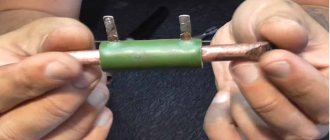
Let me remind you that we have in our hands a soldering iron with a torn off power cord. Tasks for the next half hour:
a) get acquainted with the internal structure of the hero of the review; b) if possible, bring him back to life.
The first thing we do is remove the handle made of heat-resistant plastic. What remains in your hands is – let’s call it that – a “casing”, in which all the patient’s insides are actually located.
We unscrew the only bolt - two or three turns allow you to fix or release the rod, which actually does the soldering, and its complete separation from the thread allows you to remove the “cartridge” for the rod.
On the other side of the “casing” we bend two antennae and first carefully take out two thin tubes about 4 cm long, metallic in color, and behind them is the heating element itself - a tube of the same type of larger diameter and length, in which a metal spiral with high resistivity (most likely nichrome).
As you can see, the contacts of our spiral remained intact - great news. To ensure the integrity of the heating element, you can measure the resistance between the contacts. For a 25W soldering iron, it resists approximately 2kOhm +/-100Ohm.
Here's everything that any standard soldering iron consists of:
The next step is to connect the contacts of the spiral to the power cord. Don’t forget that you first need to “put” a soldering iron handle and a white heat-shrink tube on the cord, and small tubes on each wire that serve to isolate one contact from the other
(although they look like metal, in fact they do not conduct current, they crumble easily and peel off. In addition, they are not afraid of high temperatures).
You can cheat - connect the wires somehow, but in this case it is possible that the patient will soon get sick again, so it’s better to overdo it.
It turns out? Then everything is simple - we put our insulating tubes on the exposed wire, slide a white polyvinyl chloride heat-shrink tube closer, and place the whole thing in the “casing” of the heating element.
Since the rod holder and the rod itself have become fairly smoked during operation, I advise you to lightly clean them with fine sandpaper, and additionally flatten the “cartridge” slightly - to achieve better contact and heat transfer from one to the other.
We place the cartridge with the rod in the “casing” on the other side and secure it with a screw.
Just in case, we check the resistance again, this time between the contacts of the power plug. It shouldn’t have changed, so if it increases, it means you have a bad connection somewhere. If the resistance is close to zero, you have managed to create a short circuit somewhere in this simple circuit. Neither the first option nor the second, of course, are suitable for any real testing and, especially, work. We disassemble the soldering iron again, correct the errors, and reassemble in the reverse order. Is everything okay now? Okay, then you can bend the antennae of the “casing” of the heating element...
...and put a plastic handle on it. Just in case, let's also check the resistance between the contacts of the power plug. Now the soldering iron can be plugged into the network with a confident hand. Particularly timid people can hide behind the sofa and turn on the soldering iron through a power extension cord or even a switch in the hallway :). Everything _must_ work. Personally, I succeeded. The whole thing took about half an hour. For the whole day I received a charge of energy from a folk craftsman - you can move to new heights!
And in fact, the soldering iron dear to my heart not only came back to life, but even began to heat up faster and solder better - thanks to a decrease in the thermal resistance of the “heating element - cartridge - rod” system!
I hope this note will be useful to someone in practice, and in the meantime may nothing ever break or burn for you!
Electrical circuit of a soldering iron
As you can see in the drawing, the electrical circuit of the soldering iron is very simple, and consists of only three elements: a plug, a flexible electrical wire and a nichrome spiral.
As can be seen from the diagram, the soldering iron does not have the ability to adjust the heating temperature of the tip. And even if the power of the soldering iron is chosen correctly, it is still not a fact that the temperature of the tip will be required for soldering, since the length of the tip decreases over time due to its constant refilling; solders also have different melting temperatures. Therefore, in order to maintain the optimal temperature of the soldering iron tip, it is necessary to connect it through thyristor power regulators with manual adjustment and automatic maintenance of the set temperature of the soldering iron tip.
Soldering iron device
The soldering iron is a red copper rod, which is heated by a nichrome spiral to the melting temperature of the solder. The soldering iron rod is made of copper due to its high thermal conductivity. After all, when soldering, you need to quickly transfer heat from the soldering iron tip from the heating element. The end of the rod is wedge-shaped, is the working part of the soldering iron and is called the tip. The rod is inserted into a steel tube wrapped in mica or fiberglass. A nichrome wire is wound around the mica, which serves as a heating element.
A layer of mica or asbestos is wound over the nichrome, which serves to reduce heat loss and electrically insulate the nichrome spiral from the metal body of the soldering iron.
The ends of the nichrome spiral are connected to the copper conductors of an electrical cord with a plug at the end. To ensure the reliability of this connection, the ends of the nichrome spiral are bent and folded in half, which reduces heating at the junction with the copper wire. In addition, the connection is crimped with a metal plate; it is best to make the crimp from an aluminum plate, which has high thermal conductivity and will more effectively remove heat from the joint. For electrical insulation, tubes made of heat-resistant insulating material, fiberglass or mica are placed at the junction.
The copper rod and nichrome spiral are closed with a metal case consisting of two halves or a solid tube, as in the photo. The body of the soldering iron is fixed on the tube with cap rings. To protect a person’s hand from burns, a handle made of a material that does not transmit heat well, wood or heat-resistant plastic, is attached to the tube.
Design
The operation of electric soldering irons requires knowledge of their designs in order to quickly identify damage and repair the device at any unexpected moment. It consists of:
- a copper rod wrapped in insulating material and placed in a steel tube;
- heater;
- tips for directly connecting metal parts with solder;
- handle holder;
- cord with plug.
The copper rod is an effective conductor of heat from the heater (nichrome spiral) to the tip. The spiral is wound onto a steel tube, which is wrapped in mica or fiberglass. Next, the nichrome winding is covered with an insulator (preferably asbestos), which prevents heat loss and short circuits.
Nichrome heating spiral
To reduce heating in the area of connection with the conductors of the power cord, the ends of the spiral are bent in half, and the contact point is supplemented with a crimping aluminum plate. Electrical insulation is ensured by insulating tubes placed at the twisting point.
The rod and heater are placed in the body of the soldering iron, onto which a wooden or thermoplastic handle with an internal channel for the power cord is attached.
Soldering iron supply voltage
Electric soldering irons are produced designed for mains voltages of 12, 24, 36, 42 and 220 V, and there are reasons for this. The main thing is human safety, the second is the network voltage at the place where the soldering work is performed. In production where all equipment is grounded and there is high humidity, it is allowed to use soldering irons with a voltage of no more than 36 V, and the body of the soldering iron must be grounded. The on-board network of a motorcycle has a DC voltage of 6 V, a passenger car - 12 V, a truck - 24 V. In aviation, a network with a frequency of 400 Hz and a voltage of 27 V is used.
There are also design limitations, for example, it is difficult to make a 12 W soldering iron with a supply voltage of 220 V, since the spiral will need to be wound from a very thin wire and therefore many layers will be wound; the soldering iron will turn out to be large and not convenient for small work. Since the soldering iron winding is wound from nichrome wire, it can be powered with either alternating or direct voltage. The main thing is that the supply voltage matches the voltage for which the soldering iron is designed.
Voltage
To comply with safety precautions, the soldering iron is selected according to the mains voltage from 12 to 220 V (5 values in total). Thus, work in passenger vehicles can be carried out with a soldering tool at 12 V, in trucks - 24, in air - 27, in a damp room with mandatory grounding of electrical equipment - 36 V.
How to solder a wire without a soldering iron
It is not easy to convert a 12 V tool to 220 V - you will have to wind a thin spiral with a large number of layers, which creates certain inconveniences when working with small parts.
Note! If the power of the network and the soldering iron match, you can work from alternating and direct voltage. This possibility is due to the nichrome material of the heater.
Basically, the voltage in soldering tools is 220 V. To prevent electric shock in high humidity or dusty areas, use a tool voltage of no more than 42 V.
Soldering iron heating power
Electric soldering irons come in power ratings of 12, 20, 40, 60, 100 W and more. And this is also no coincidence. In order for the solder to spread well over the surfaces of the parts being soldered during soldering, they need to be heated to a temperature slightly higher than the melting point of the solder. Upon contact with a part, heat is transferred from the tip to the part and the temperature of the tip drops. If the diameter of the soldering iron tip is not sufficient or the power of the heating element is small, then, having given off heat, the tip will not be able to heat up to the set temperature, and soldering will be impossible. At best, the result will be loose and not strong soldering.
A more powerful soldering iron can solder small parts, but there is a problem of inaccessibility to the soldering point. How, for example, can you solder a microcircuit with a leg pitch of 1.25 mm into a printed circuit board with a soldering iron tip measuring 5 mm? True, there is a way out: several turns of copper wire with a diameter of 1 mm are wound around such a sting and the end of this wire is soldered. But the bulkiness of the soldering iron makes the work practically impossible. There is one more limitation. At high power, the soldering iron will quickly heat up the element, and many radio components do not allow heating above 70˚C and therefore the permissible soldering time is no more than 3 seconds. These are diodes, transistors, microcircuits.
Power
How to make a dimmer for a soldering iron
The operating power of the soldering iron is selected from 12 to 3000 W and determines its technical capabilities. Soldering of small parts is performed with a 12 W device. This condition must be met, since a powerful soldering iron, due to the size of the tip, will not be able to reach the contact points of tiny radio elements. In addition, the high power of the device causes unacceptable overheating of the circuit parts.
Soldering iron 12 W
For powerful radio components, thick wires and small elements, 40 and 60 W soldering irons are required. If work is performed on large equipment, then the soldering tool is selected for 100 W or higher. If the power of the device is insufficient, the soldering will be weak and have a large number of voids.
DIY soldering iron repair
The soldering iron stops heating for one of two reasons. This is a result of chafing of the power cord or burnout of the heating coil. Most often the cord frays.
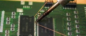
Checking the serviceability of the power cord and soldering iron coil
When soldering, the power cord of the soldering iron is constantly bent, especially strongly at the point where it exits and the plug. Usually in these places, especially if the power cord is hard, it frays. This malfunction first manifests itself as insufficient heating of the soldering iron or periodic cooling of it. Eventually, the soldering iron stops heating.
Therefore, before repairing the soldering iron, you need to check the presence of supply voltage in the outlet. If there is voltage in the outlet, check the power cord. Sometimes a faulty cord can be determined by gently bending it where it exits the plug and soldering iron. If the soldering iron becomes a little warmer, then the cord is definitely faulty.
You can check the serviceability of the cord by connecting the probes of a multimeter turned on in resistance measurement mode to the pins of the plug. If the readings change when bending the cord, the cord is frayed.
If it is discovered that the cord is broken at the point where it exits the plug, then to repair the soldering iron it will be enough to cut off part of the cord along with the plug and install a collapsible one on the cord.
If the cord is frayed at the point where it exits the soldering iron handle or the multimeter connected to the pins of the plug does not show resistance when bending the cord, then you will have to disassemble the soldering iron. To gain access to the place where the spiral is connected to the cord wires, it will be enough to remove only the handle. Next, touch the multimeter probes successively to the contacts and pins of the plug. If the resistance is zero, then the spiral is broken or its contact with the cord wires is poor.
Calculation and repair of the heating winding of a soldering iron
When repairing or making your own electric soldering iron or any other heating device, you have to wind a heating winding made of nichrome wire. The initial data for calculating and selecting wire is the winding resistance of a soldering iron or heating device, which is determined based on its power and supply voltage. You can calculate what the winding resistance of a soldering iron or heating device should be using the table.
Knowing the supply voltage and measuring the resistance of any heating electrical appliance, such as a soldering iron, electric kettle, electric heater or electric iron, you can find out the power consumed by this household electrical appliance. For example, the resistance of a 1.5 kW electric kettle will be 32.2 Ohms.
Step-by-step instruction
Independent production or repair of heating devices is carried out taking into account the calculation of the resistance of the heating element or winding. Knowing the voltage and resistance values of an electrical appliance allows you to calculate its power that it consumes. The resistance in the winding of a 60 W soldering iron, powered by a 36 V network, should reach 22 Ohms. Correct selection of power and voltage helps to avoid breakdown and the need to repair the device in question.
Schemes of temperature controllers for the soldering iron tip.
Then you need to select the diameter of the nichrome wire, comparable to the dimensions of the winding. The spiral winding with a resistance of 806 Ohms is performed using 5.75 m of wire with a diameter of 0.1 mm (the resistance value is divided by 140) or 25.4 m of wire with a diameter of 0.2 mm. The coils must be laid closely. The surface of the nichrome wire will oxidize when heated, creating an insulating surface. The wound layer, which does not fit into the first row, is covered with mica. Wind up the second row. High-quality assembly allows you to operate the tool for a long time without breakdowns or repairs.
Thermal and electrical insulation in the winding is provided by a coating made of fiberglass, mica or asbestos. The advantage of asbestos over other compounds is that it can be soaked with water, creating the required shape, and after drying, the material has a fairly high strength.
Simple repairs help restore its functionality. To repair a soldering iron, you will need the following tools:
- pliers;
- sharp knife;
- ceramic resistance “PEV-10”;
- asbestos thread.
Repair of an electric soldering iron is carried out in several stages. A 1-1.5 Ohm ceramic resistor is pre-prepared. In its central part there is a hole that allows you to pass the soldering iron rod without additional adjustment.
Everything about the rules for operating an electric soldering iron and do-it-yourself repairs
An electric soldering iron is a hand-held tool for joining parts. This property is due to the presence of soft solders, which heat the material to a liquid consistency and fill all voids. Before buying a soldering iron, you need to read the instructions for its operation in order to understand what to do if it breaks down. This article describes in detail how to properly repair an electric soldering iron.
Rules for using power tools
On the shelves of construction stores you can find different models of electric soldering irons that operate on mains power - from 12 to 220 W. The process of choosing a tool should take into account the safety of the working craftsmen and the voltage in the electrical network at the work site.
If the instrument is made independently, then a thin wire will be required for its correct reconstruction. It will be wound onto a spiral. The required power is from 12 to 100 W, even more is possible. The material will spread evenly over the surface of the plates if the melting temperature exceeds the temperature in the soldering iron itself.
terms of Use
There are models on the market that are suitable for operation from a network with voltages from 12 to 220 V. In the process of choosing a tool, the need to ensure the safety of the craftsmen working with it and the voltage in the electrical network at the work site are taken into account.
In rooms with high humidity levels and grounded devices, it is permissible to use a soldering iron with a voltage of up to 36 V and mandatory grounding of the soldering iron body. There is no need to repair the instrument if these requirements are met.
Electric soldering iron device.
When making your own soldering iron, a thin wire is used to wind the spiral. The supply and tool voltages must match each other. The power of such units reaches from 12 to 100 W and higher, because it is possible to ensure that the solder spreads evenly over the surface of the elements being connected if they are heated above its melting point. Heat from the tip is transferred to the parts upon contact, because of this the temperature of the tip decreases.
Insufficient power of the heating coil or small diameter of the rod may prevent the tip from heating to the required temperature, which prevents soldering. Powerful soldering irons can be used to connect small parts, but due to the size of the device, access to the soldered elements is limited. Experts recommend winding a copper wire with a diameter of 1 mm around the tip. The high power of such devices allows you to quickly warm up the elements, and most small radio components, transistors, diodes, microcircuits cannot withstand temperatures exceeding 70 ° C. Soldering time is reduced to 3 seconds. Before you repair the device in question, you will need to find out its design features.
Main details
The soldering device is made from a copper rod. A nichrome spiral heats the device.
It is important that the heat is immediately transferred from the heating element to the tip - this is the name given to the rod with a wedge-shaped tip. It is inserted into a steel tube, which is wrapped in glassy fabric or mica. A wire is wound around the mica, which serves as a heating element. To reduce heat loss, nichrome wire is wrapped with asbestos. The ends of the nichrome spiral are connected to the conductors of the electrical cord. To ensure reliability and preservation of the generated heat, the spirals are bent and folded in half at the point of connection with the copper wire. Additionally, they are compressed at the coupling point.
Electrical diagram
Power
The electrical power of a soldering iron is the amount of electricity that the device is capable of taking from the network. The value can be determined by multiplying the voltage by the current consumed. This number shows the thermal power dissipated on the tip and determines the operational capabilities of the device.
The choice of power depends on the planned operation of the tool.
- When soldering small parts within the house, garden or garage, a soldering iron with low power will suffice.
- For large materials, the most powerful tools are suitable, which consume the maximum amount of energy to cope with melting and soldering.
To change the charge of electricity to the required one, it is enough to replace the tip with a thicker tip.
If the heating element fails, the power is taken into account if it is necessary to rewind it independently and select the number of turns.
Voltage
An important characteristic when repairing a soldering iron if it breaks is the voltage supplied to the winding. Depending on the model produced, the indicator can take the following values:
- 220 volt . Typical for domestic production.
- 12–42 volts . They are reduced by a transformer for safety reasons, but emit increased power for soldering complex parts in hazardous working conditions.
- 5 volts . It is possible to make such soldering irons yourself. These are miniature tools for performing simple work at home and in small-scale production.
Reduced voltages are important for working in hazardous environments. For example, with high room humidity, heavy smoke or dirt. The purpose of reducing voltage is to ensure safety at work and prevent accidents from possible electric shock.
Manufacturing stages
The first stage is performing calculations. They are based on the laws of physics, in particular Ohm's law. For example, a 100 ohm resistor will be used for manufacturing. The current strength in this case will be 2.2 A, which means that the power of the soldering iron will become 484 W, which is too much for such a device. This means that you will need to reduce the voltage using a capacitor (it is better to take a 10 µF part up to 300 V). In this way, you can reduce the voltage by almost 4 times, that is, to 0.5 A, obtaining a soldering iron power of 55 W, which is less than the original one.
After the calculations have been carried out and the necessary materials and tools have been prepared, you can proceed to mechanical assembly. It is performed in the following sequence:
- First you need to make a sting from a copper rod. To do this, you need to sharpen one end of the wire to a bilateral angle of 40-45°. It is not necessary to maintain this angle; it is enough to sharpen at the angle at which it will be convenient to work in the future. Tin the processing area.
- Wrap the tip in copper foil, leaving the working part free (no more than 10 mm), then place the tip in the resistor, fix it with an insulating mixture (you must first combine silicate glue and talc to obtain a dough-like mass). This also protects the main part from cracks during operation. The insulating layer must be baked by holding the device over a heat source.
- If nichrome wire is used, it is wound on silicate glue and then covered again with an insulating layer.
- Strengthen the insulation at the junction of the wires and the heating element, for which asbestos thread is suitable (you can additionally use a ceramic sleeve).
- The resulting structure must be placed in a prepared iron tube, onto which a handle made of heat-resistant material (preferably wood or PCB) is then attached. First, you need to cut a hole in the hole of the handle through which to pass the wire (by analogy with industrial soldering irons), with the help of which the device is connected to the network.
Before work, you need to check the functionality of the soldering iron; it is recommended to connect it to the network through a transformer or into a 12-volt power supply, which is designed for a current of 1 A.
Possible causes of failure
Break in the wiring
A power outage is the most common cause of device failure. If the fault is in the electrical cord, then you can correct the situation yourself. It is enough to replace the cord or plug depending on which part of the wiring there is a break.
If the nichrome winding breaks, the repair is carried out in more complex stages, but it is also possible to fix it yourself. To determine whether the winding is broken and repaired, a special device called a multimeter is used. Its use depends on the power, which is indicated on the soldering iron body or in the passport.
The fixing rings are moved apart, and the protective housing of the soldering iron winding is removed. The protection casing is available in two types:
- A metal tube is attached to the winding pin, which rests against the handle and is secured with a clamping ring in the place where the tip is located.
- The protective housing consists of two longitudinal halves of the tube, the edges of which are noticeably reduced in diameter. The two components are secured with clamping rings.
Burnout
The bending area when using a soldering iron is the most vulnerable to parts burning out.
Where the wire enters the soldering iron itself is where repairs need to be done. Having disassembled the tool, you need to ring the wires coming from the plug, and then cut off a small piece (no more than 15 cm) from the entrance to the soldering iron. If there is no contact even with this action, then the piece is cut off from the fork side. In many cases, it is not possible to repair the burnt-out part on your own and restore contact. In this case, you need to replace the wire with a new one, following all the steps described above. If the heating tool itself burns out inside the soldering iron, then this is much more difficult, but it can be eliminated. Repair in one of the following ways:
- Rewind the heating coil if the soldering iron was designed for a power of no more than 36 volts. The supply voltage of 220 volts complicates the task. A thin long wire is wound around the base of the heater. The forks should not have direct contact.
- Replace the entire burnt heating element, which is fixed with one screw, the shortest in length. The tip is fixed with a longer screw.
We suggest watching a video on how to repair a burnt soldering iron:
Bad contacts
In many cases, if there is poor contact, you need to check the voltage supply in the electrical network. If the power of the electric current corresponds to the norm, then the cause of poor contact may be the following:
- Incorrect sting position . It is enough to insert it a little deeper into the body and secure it. If the rod is short, replace it with a suitable one.
- Scale on the tip . Removable with simple sandpaper or a file. The heated tip is dipped in rosin and the tip is rubbed on the braid with solder. When a thin and even layer of solder forms on the tip, the scale has been completely removed.
Why doesn't the soldering iron heat up? How to fix it?
Most often, the cause of this malfunction is poor contacts. First check the voltage supply. If it turns out that the current power is normal, then most likely the malfunction is caused by an incorrect location of the tip. This happens especially often in electrical appliances with retractable rods and screw terminals. Often the tip wears off or for some other reason ends up being too protruded from the body. If the working surface is located normally, then its end part in the form of a core is completely located in a mica tube. Thus, the contact of the rod with the heating element occurs fully, due to which the tip heats up more. If it is removed from the tube at least halfway, the heating intensity will decrease significantly. Repairing the device is easy. Home craftsmen insert the sting deeper into the body and fix it. It may be that the rod turns out to be too short. In this case, it is replaced. Also, the soldering iron may not work due to scale on the tip. It is removed, if necessary, and then the surface is cleaned using ordinary fine-grained sandpaper or a needle file.
The sting is then heated and dipped in rosin, after which its tip is rubbed on a braid with solder. As a result of such actions, the rod will be covered with an even layer of solder. Experts recommend performing this procedure more often with soldering irons equipped with copper rods, since scale forms on them faster. Also, the soldering iron may not heat up due to improper sharpening of the tip. For effective heat transfer, the working surface must have the shape of an oval bevel.
Step-by-step instructions on how to repair it yourself
Soldering iron repair begins with calculating the resistance of the heating element or winding. The voltage and resistance values of an electrical appliance allow you to calculate its power consumption. For example, the resistance in the winding of a soldering iron with a power of 60 W and powered from a 36 V network should be equal to or slightly more than 22 Ohms.
For repairs, you need to prepare the following tools:
- pliers;
- sharp knife;
- ceramic resistance “PEV-10”;
- asbestos thread.
A ceramic resistor is pre-prepared. The power wires must be close to its base to test the electronic power and heat dissipation.
You need to have nichrome wire on hand; its diameter must correspond to the parameters of the winding. The coils are laid closely. When heated, the surface of the nichrome wire will oxidize, creating an insulating layer. The wound layer, which according to the rules should not be placed in the first row, is covered with mica and placed in the second row.
How to repair
To prevent sudden damage to the instrument from causing inconvenience, every specialist or radio amateur must confidently wield a soldering iron and be able to repair it, especially since it is not difficult. It is necessary to have a conventional ampere-voltmeter that diagnoses the type of malfunction.
Replacing the heater with a new one
If the heating element loses its functionality, do the following:
- determine the winding resistance based on the power of the device and the network voltage;
- select the diameter of the nichrome wire according to the resistance of 1 meter;
- wind the spiral, laying the turns without gaps, placing a layer of mica between the rows;
- in order to retain heat and prevent short circuits, the winding is covered with fiberglass, instead of which mica or asbestos can be used; the latter has the advantage of creating the required shape and acquiring strength after drying.
Note! After applying the asbestos insulating layer, you need to wait for it to dry and only then turn on the device to the network.
Replacing the heater with a resistor
Instead of a heating element, you can successfully use a PEV-10 resistor. To repair a soldering iron with your own hands, you will need pliers, a well-sharpened knife, and asbestos thread. To replace the heater, you must:
- disassemble the soldering tool;
- remove the used heater;
- place the resistor in the vacant space;
- remove 1.5 cm of insulating coating from the power cord, connect the power wires to the resistor through the holder channel; make sure that the laid wires do not touch the housing; insulate the terminals with asbestos thread;
- assemble the tool and make sure it works.
If the power cord is damaged, it should be replaced. A faulty power cord plug must also be replaced. In this case, the broken fork (usually a solid one) is cut off and a collapsible one is installed instead.
Broken contact of the heater with the power cord can be easily eliminated. To do this, you need to disassemble the soldering iron and restore the connection of the contacts.
If you work with the soldering iron carefully, it will not require repair for a long time. If damage does occur, it is quite simple to fix it: you need to know the circuit diagram of the device (it is elementary), the basic rules of electrical engineering and safety.
Expert advice
To successfully repair the email. soldering iron with your own hands, you need to do it as experts advise:
- When rewinding a spiral, you must carefully ensure that adjacent turns are located at a distance from one another. A mica spacer must be placed between the winding rows.
- When soldering deformed or faulty parts, mechanical stress on the cord must be avoided. This will preserve the electric heater for a long time.
- Do not leave the soldering iron coil on for a long time to avoid short circuiting of the electrical wiring if the parts included in it malfunction.
- During repairs, you need to use the power regulator to select a safe heating mode for the tip.
- If it was not possible to avoid overheating of the device and use the tip safely, then carefully isolate the melted area. This is done with electrical tape and cambric placed over the damaged tip.
It’s easy to repair a soldering iron with your own hands. To do this, you need to understand the causes of the malfunction and correctly calculate the power of the electrical network for operation.