Is grounding necessary in a private house?
When using any electrical appliances in the house, there is always a risk of damaging the insulation of the wires or shorting them to the housing.
In this case, any person touching the dangerous zone leads to electric shock, which can end tragically. The current always tends to the ground, and the human body becomes a conductor connecting the damaged device to the ground. What does grounding do? Essentially, it is a system that provides the shortest path for electrical current. According to the law of physics, he selects the conductor with the lowest electrical resistance, and the circuit has this property. Almost all the current is directed to the ground electrode, and therefore only a small part of it will pass through the human body, which cannot cause harm. Thus, the ground loop ensures electrical safety. Regulatory documents (GOSTs, SNiP, PUE) indicate that any private, residential building must be equipped with it for alternating current networks with voltages above 40 V and alternating current networks with voltages above 100 V.
In addition to ensuring safety, the grounding system increases the reliability and durability of household appliances. It ensures stable operation of installations, protection against overvoltage and various network interferences, and reduces the impact of external sources of electromagnetic radiation.
Grounding should not be confused with lightning rods (lightning rods). Although the principle of their operation is similar, they perform different tasks. The job of a lightning rod is to divert lightning into the ground when it hits a house. In this case, a powerful electric charge arises, which should not enter the internal network, because can simply melt a wire or cable. That is why the lightning rod line runs from the receivers on the roof along the outer contour and should not be combined with the grounding, internal line. The lightning rod and grounding may have a common underground circuit (if it has a margin in cross-section), but the wiring must be separated.
Types of protection against electric shock
In accordance with paragraph 1.1 of GOST 12.1.030-81, protective grounding or grounding (zero-ground connection) is designed to protect people from electric shock in the event of insulation damage when they touch metal non-current-carrying parts of electrical equipment.
Grounding is an intentional or accidental electrical connection of metal parts of electrical equipment, electrical installations, or a network point to a grounding device, busbar or other protective equipment (clause 01-10-09 GOST R 57190-2016).
This could be reinforcement in the ground, building structures or special electrodes. This measure is a mandatory deliberate protection of both residential and non-residential assets.
Grounding is the deliberate connection of metal parts that are not energized in the normal state with a neutral protective conductor (solidly grounded neutral of a transformer or generator).
In accordance with paragraphs 1.1.2, 1.1.3, 1.7 of GOST 12.1.030-81, grounding must be done by electrically connecting metal parts of electrical equipment to a grounded point of the power supply using a neutral protective conductor (PE).
For neutral protective and grounding conductors, you can use: special conductors, as well as metal structures of buildings and structures.
Protective grounding and grounding of electrical equipment must be carried out without fail when using an alternating current voltage with a nominal value of 220 (1 phase) and 380V (3 phases) and higher and a direct current voltage of 440V and higher. In addition, according to clause 1.7.13 of the PUE, the power supply for electrical receivers must be supplied from a 380/220 V network with a TN-S or TN-CS grounding system.
Features of the TN-CS power supply system
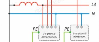
Residential areas are powered using step-down transformers with a solidly grounded neutral. This means that the secondary windings are connected in a star configuration, the middle point of which is connected to the ground loop without breaks or switches.
Modern safety measures provide for a five-wire TN-S power supply circuit - 3 phase wires, neutral and ground. The last two conductors are connected to the neutral of the supply transformer.
The transfer of all residential buildings to this power supply scheme involves replacing the previously used four-wire TN-C system and will be quite expensive. Therefore, a compromise option was developed - the TN-CS grounding system.
Its description and technical requirements are specified in the PUE pp. 1.7.3, 1.7.131-135 and Fig. 1.7.3. The main feature of this power supply option is the use of a combined PEN conductor in the section from the supply transformer to the entrance to the building, where it is divided into two wires - neutral N and grounding PE. At the separation point, according to PUE clause 1.7.61, these wires must be connected to the building’s grounding loop.
Grounding schemes: which one is better to make?
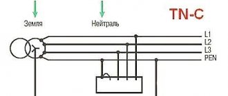
The grounding system of a private house depends on the type of network connection to it. Most often, it is performed according to the TN-C principle. Such a network is provided by a two-core cable or two-wire overhead line at a voltage of 220 V and a four-core cable or four-wire line at 380 V. In other words, a phase (L) and a combined protective neutral wire (PEN) are supplied to the house. In full-fledged, modern networks, the PEN conductor is divided into separate wires - working or neutral (N) and protective (PE), and the supply is carried out by a three-wire or five-wire line, respectively. Taking into account the above options, the grounding scheme can be of 2 types.
TN-CS system
Provides for dividing the PEN input into parallel conductors. To do this, in the input cabinet the PEN conductor is divided into 3 buses: N (“neutral”), PE (“ground”) and a splitter bus for 4 connections. Further, conductors N and PE cannot contact each other. The PE bus is connected to the cabinet body, and the N-conductor is installed on insulators. The grounding circuit is connected to the bus splitter. A jumper with a cross-section of at least 10 sq. mm (for copper) is installed between the N-conductor and the ground electrode. In further wiring, “neutral” and “ground” do not intersect.
Reference! It is important to consider that this system is effective only when installing an RCD and a differential-type circuit breaker.
TT system
In such a circuit, it is not necessary to split the conductors, because the neutral and earth conductors are already separated in a suitable network. The cabinet simply makes the correct connection. The grounding circuit is connected to the (residential) PE wire.
The question of which grounding system is better does not have a clear answer. The CT circuit is simpler to install and does not require additional protective devices. However, the vast majority of networks operate on the TN-C principle, which forces the use of the TN-CS scheme. In addition, electrical installations with two-wire power supply are often used in everyday life. When the CT is grounded, the housing of such devices becomes energized if the insulation is damaged. In this case, TN-CS grounding turns out to be much more reliable.
Why two buses if they are connected anyway?
The very name of the TN-CS grounding system indicates that the neutral N and ground PE are combined only on part of the line. In the building they must be separated into separate wires. This was done for a number of reasons:
- the PEN wire laid in the area from the transformer to the entrance to the building has a larger cross-section and is less likely to fail than electrical wiring laid inside the building;
- according to PUE clause 1.7.145, the grounding wire cannot be disconnected, while the neutral conductor must be disconnected when repairing wiring and equipment.
How to connect grounding in a panel
It’s hard to imagine coziness and comfort in a private house or apartment without an established power supply system. Electricity consumption is constantly increasing, making it more difficult to protect people and pets from electric shock. Risks can be eliminated and the consequences of injuries can be minimized using a grounding system that connects points of the electrical network or energy consumer to a grounding structure.
Grounding
Grounding is a single conductor or a group made up of them in contact with the ground. With its help, the voltage supplied to the metal body of the units is reset along the path of zero resistance, i.e. to the ground.
Such electrical grounding and grounding of electrical equipment in industry is also relevant for household appliances with steel external parts. A person touching the body of a refrigerator or washing machine that is energized will not cause electric shock. For this purpose, special sockets with a grounding contact are used.
Design and purpose of grounding devices
Such structures are divided into working and protective devices.
- The worker is used to organize the safe operation of industrial units. Also common in private households.
- A protective grounding system is required for electrical networks in the residential sector.
Installation of a grounding device (GD) is required in accordance with the Rules for the Construction of Electrical Installations and the Rules for the Operation of Consumer Electrical Installations.
People touching live parts exposed as a result of improper operation of electrical equipment, design defects, deterioration of insulation and other reasons is common. Poor-quality design of the charger and its installation can lead to serious consequences for people: electric shock, burns, disruption of the heart and other human organs, electric shock often leads to amputation of limbs, disability and even death.
The grounding system consists of external and internal parts, which are joined in the electrical panel. An external grounding device consists of a complex of metal electrodes and conductors that drain emergency current from electrical equipment into the ground in places that are safe for people. The electrodes are called ground electrodes. Electrical conductors are grounding conductors; they are pins 1.5 m long and 1 mm in diameter.
They are manufactured industrially from copper or copper-plated steel. Their main advantage is increased current conductivity. They are driven into the ground with hammers or sledgehammers to a depth of 50 cm; contact with the ground must be as strong as possible, otherwise the structure’s ability to drain current will deteriorate.
The simple design is made from a single electrode. Used in lightning rods or to protect remote objects and equipment. In individual farms, preference is given to multi-electrode devices. They are placed in one row and are called linear memory profiles. The standard chain length is 6 meters. They are connected to each other using brass couplings; the fastening is threaded; welding is not recommended. Grounding conductors are installed through terminals. Twisting and soldering of cores are excluded.
Don't miss: Primer for floors under tiles: types of primer, features and procedure for priming a concrete floor. Floor primer for bathtub tiles
A device such as a ground loop (closed version) is still common. It is constructed at a distance no closer than 1 meter and no further than 10 meters from the house. Placed in a trench in the form of an equilateral triangle. Side length 3 m, depth – 50 cm, width – 40 cm. Grounding conductors are driven into the corners. The same operation is performed with other vertical electrodes (no more than five units). Grounding conductors in the lower supporting part are welded to horizontal products.
They are made of copper, copper or zinc coated steel angle (5 mm flange, 40 mm strip). A standard stainless steel angle of any profile is often used. The products are not painted, as in this case the electrical properties will deteriorate due to weakened contact with the ground.
The design of the circuit is simple; you can do it yourself. But the work is simplified when using ready-made grounding devices on the market, complete with grounding wires. Financial losses will be recouped through the use of high-quality materials that are resistant to corrosion and have a long service life.
Let's analyze the situation with diagrams
From the point of view of the flow of electric current, there is no difference between grounding and grounding. The neutral wire in any case has electrical contact with physical ground.
Accordingly, when a phase is shorted to the housing, the same short circuit will occur and the circuit breaker will turn off. Of course, (subject to proper connection: the socket must have a third ground contact, just like an electrical appliance. For this reason, electricians, violating the requirements of the Electrical Installation Rules, often separate the ground bus from the zero contact of the input panel.
Let's imagine a situation where the neutral wire is broken for some reason:
- loss of contact due to corrosion (in old high-rise buildings this is a working situation);
- mechanical rupture of the cable due to repair work with violations of technology (unfortunately, also not uncommon);
- unauthorized intervention by a home-grown “electrician”;
- accident at the substation (only the zero bus may be disconnected).
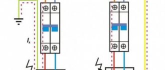
In the diagram it looks like this:
When organizing protective grounding, the electrical circuit between the physical “ground” and the grounding contact of the electrical appliance is broken. The installation becomes defenseless. In addition, a free phase without a load can create a potential equal to the input voltage at the nearest substation. Typically this is 600 volts. You can imagine the damage that will be caused to the electrical equipment that is turned on at this moment. In this case, there is no current leakage to the physical ground, and the circuit breaker will not trip.
Imagine that at this moment you simultaneously touch a phase (a breakdown on the body of an electrical installation) and a metal object that has a physical connection with the ground (a water tap or a heating radiator). You can get electrocuted at 600 volts.
Now let's see what the difference is between grounding and neutralizing (in our diagram). If the zero bus breaks, the power to all electrical installations in this circuit will simply disappear. There will be no electric shock under any circumstances: the electrical circuit between the physical ground and the grounding contact of electrical appliances is not broken. We have already preserved our health. Now let's see what happens to electrical installations. The maximum damage is a burnt-out incandescent lamp closest to the input panel. Moreover, trouble will only occur if the voltage on the phase wire increases. The current strength will increase (according to Ohm's law), the circuit breaker will work, and perhaps other electrical appliances will not be affected.
It is for this reason that the PUE strictly prescribes: protective grounding and grounding of electrical installations must be organized independently of each other, using different lines.
For reference: Wire color coding is usually used:
- The phase is brown or white.
- The working zero is blue.
- Protective grounding is a yellow-green shell.
If you have a modern home, then grounding and grounding are carried out in accordance with the Electrical Installation Rules. This can be easily checked by looking at the input cable in the panel. In addition, you can check the correct connection yourself.
Operation of the grounding device
To connect the grounding device to the housing of household or industrial equipment, a PE conductor is used, which is led out of the panel via a separate line with a special output. The design provides a connection between the housing and the ground, which is the purpose of grounding. The difference between grounding and grounding is that at the initial moment when connecting the plug to the socket, the working zero and phase are not switched in the equipment. The interaction disappears at the last minute when the contact opens. Thus, the chassis grounding has a reliable and permanent effect.
Connecting the external part of the charger to the shield
To determine the exact procedure for connecting the grounding to the panel, knowledge of the method of using the neutral is required. It can be isolated and grounded. The insulated core is used in networks with increased voltage values of 3-35 kV. With a power supply of 380 V and 220 V, both options work effectively. However, the new PUE rules require the neutral to be grounded. The circuits must be built for voltages up to 1000 V.
Popular grounding systems are TN-C, TN-S, TN-CS. Two-phase TN-C is outdated, but is still used in buildings that have a long service life. Their replacement is associated with technical and financial difficulties. In this circuit, the neutral conductor is used as a protective ground wire. From a practical point of view, for residents of apartments and houses, cable and conductor products with 4 cores are beneficial: their cost is lower and installation work is simpler.
The question of how to connect grounding in a multi-storey building is of interest. The conductors are connected to the common memory bus. The bus is then routed to the electrical panel housing on the floor. The process of converting TN-C to TN-CS in the home panel is similar. The idea is to connect the neutral protective conductors to a single bus of the charger and then attach it with a jumper to the zero bus.
The main disadvantage is associated with the risk of damage to the neutral wire. Then the grounding structure will become unusable. Regulatory documents have introduced a ban on the use of TN-C in new buildings. But it will take decades to completely replace the system.
The principle of operation of TN-S is based on the fact that the zero operating and protective lines are supplied to the consumer by separate conductors from the transformer substation. In the Russian Federation and CIS countries, an intermediate version of TN-CS is common, in which the conductors are separated directly upon entry into the house. In both options, the safety functions are performed by a residual current device (RCD).
How to properly connect zero to ground
Incorrect connection of zero to ground can cause tragedy, instead of protection. In a common house input device (IDU), the combined zero must be divided into working and protective conductors. Then the protective zero should be routed to the shields on the floors, and then to the apartments.
This results in a five-wire network:
- 3 phases;
- P.E.
Don't miss: How to lay tiles in the bathroom with your own hands: step-by-step instructions
PE must be connected to the third contact of the sockets. In old houses there is a four-wire network:
- 3 phases;
- combined zero
If the PE conductor is made in the form of an aluminum busbar, then its cross-section must be at least 16 mm², if the copper busbar (brass) is at least 10 mm2. This rule is valid for ASU; otherwise, you should be guided by the table below.
Cross-section of phase conductors, mm2 Smallest cross-section of protective conductors, mm2 S≤ 16 S 16 16 S>35 S/2
Circuit breakers and other disconnecting devices cannot be installed on the PE protective conductor; it must be non-switchable. It is necessary to separate the combined PEN zero before the machines and RCDs, after them they should not be connected anywhere!
Forbidden:
- Connect the protective and neutral contacts in the socket with a jumper, because if the zero is broken, dangerous phase voltage will appear on the housings of household appliances;
- connect the neutral and protective conductors with one screw (bolt) on the busbar in the shield;
- PE and N must be connected to different buses, and each wire from each apartment must be screwed with its own screw (bolt). It is necessary to take measures against loosening of bolts and protecting them from corrosion and mechanical damage (clause 1.7.139 of PUE 7).
This connection is used in modern power supply of residential premises or private houses. Which meets the requirements of PEU-7 (clause 7.1.13) for direct and alternating current networks with a voltage of 220/380 volts. After separation, combining them is strictly prohibited.
In a private house, we often receive two or four wires from overhead power lines. Most often there are 2 situations:
Situation #1 is a good case. Your electrical panel stands on a support, and a re-grounding is driven under it. There are two buses PE and N in the electrical panel. The zero from the support and the wire from the grounding conductor go to the PE bus. There is a jumper between the PE and N buses, from the N bus there is a working zero to the house, from the PE bus there is a protective zero to the house. Buses PE and N can be installed in the house in the distribution board, then the neutral is connected to the ground on one bus in the metering board as in the photo below.
The point is to connect the zero and grounding at the input to all RCDs and automatic circuit breakers, and from this point lead the phase, neutral and ground to the consumers.
Such boards are now often assembled when connecting new private houses to the power grid. In this case, the input circuit breaker is installed in phase, the zero from the overhead power line goes directly to the meter, and the division of the zero (connection to the grounding conductor) is made after it. Less often this is done before the meter, but energy sales are often against such a decision. Why? Nobody knows, they argue about the possibility of electricity theft (the question is how?).
Situation No. 2 - The metering board can be either on a support or in the house or on its facade, it doesn’t matter. You have a sealed input machine and a meter, respectively, you have one or three phases and zero. How to make grounding and is it necessary to connect it to zero? If the overhead power line is new, it is necessary. As in the previous case, you will receive a TN-CS system. Then: the zero from the meter is connected to the PE bus, to which is a wire from the ground electrode (which you will make yourself on your site).
If the overhead power line is old, there is no need to connect the neutral and the ground (Chapter 1.7. PUE clause 1.7.59). Make a TT system (without connecting PE to N). In this case, be sure to use an RCD!
In both situations, each wire on the busbars must be tightened with its own bolt - do not put multiple PE or N conductors under one bolt (or screw).
Why are the working zero and ground connected?
The connection of the neutral and grounding conductors in the water shield with simultaneous connection to the grounding loop of the building is carried out to increase the electrical safety of the residents of the house without replacing the cables supplying the building and converting the power supply system to TN-CS.
If this operation is not performed and the combined PEN wire is connected to the grounding contacts of the sockets, then the power supply will be provided according to the TN-C scheme. In this case, instead of protective grounding, grounding will actually be used, even if this conductor is additionally grounded in the water shield.
Such a protection system does not provide the necessary safety for people due to possible breaks and poor contact in the connection point of the wires used in electrical wiring. In this case, the housings of electrical appliances will be connected to the phase wire .
Therefore, the answer to the question “whether to connect zero to ground” depends on the number of wires approaching the house. When powering a building using a four-wire circuit, this must be done in the water panel, but if there is a fifth wire in the line through which the house is connected to the substation ground loop, this is prohibited in accordance with the PUE clause 1.7.135.
But what if your house does not have protective grounding at all?
It is clear that when carrying out major repairs, electricians will replace the wiring in accordance with the Electrical Installation Rules. At a minimum, three independent wires will appear in your input panel: phase, working zero and protective ground. All that remains is to replace the wiring in the outlet network.
But major repairs can be carried out in a few years, and today you are already using a boiler and washing machine without grounding, or even worse - with a protective grounding. There is only one way out: organize grounding yourself. If you live in a private house, the technical side of the issue is significantly simplified. But for high-rise buildings, the cost and complexity of the work depends on the floor.
An alternative is to organize a grounding bus with your neighbors, with junction boxes on each staircase.
The tire must be one-piece until it is inserted into the ground. Near the foundation, preferably not in the road surface, but in a flower bed, a grounding loop is organized in accordance with the Electrical Installation Rules. Each resident of the entrance can connect to the common bus and bring “ground” into the apartment. Then there are two options:
- Organize a grounding contact group in the distribution panel, and replace all electrical wiring with three-wire wiring.
- Inside the baseboard, stretch the earth cable under each socket and insert it into the mounting boxes.
Either way, you will protect both your electrical appliances and, most importantly, your health.
Protective grounding from point “A” to point “B”
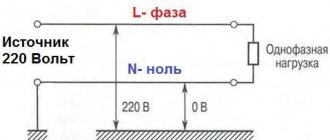
Where does the protective grounding come into our house from, is it zero or neutral? Let's look at its path from the transformer substation. As can be seen from the diagram (below), it starts with a solidly grounded neutral.
In our case, the solidly grounded neutral is the neutral of the power transformer connected to a grounding device. Then, together with the line consisting of three phases, the neutral enters the input cabinet and is distributed to the electrical panels on the floors.
The working zero is taken from it, which together with the phase forms the phase voltage that is familiar to us. Zero is called working because you use it to operate electrical appliances (electrical installations).
But a separate zero (protective zero), taken from the panel, electrically connected to a solidly grounded neutral, forms a protective zero.
Remember, there should be no separating devices or fuses in the circuit of protective grounding conductors.
Attention!
Never use a working zero as a protective zero (protective zeroing), by doing this you will endanger both yourself and the people around you.
Because if the working zero circuit breaks, the phase current through the switched-on loads will flow to the body of the electrical device, and instead of protection, you will receive an unprotected source of dangerous voltage.
The purpose of protective grounding is to eliminate the danger of electric shock when touching the body of an electrical installation or other non-current-carrying parts that are energized when a phase is shorted to the body or ground.
The operating principle of grounding is to transform the short circuit of a phase conductor to the body of an electrical installation into a single-phase short circuit. This causes a large current, which ensures rapid response of the protection of the damaged electrical installation and disconnects it from the supply network.
masstter.com
My bitter experience as an electrician allows me to say: If your “grounding” is done correctly - that is, in the panel there is a place for connecting "grounding" conductors, and all plugs and sockets have "grounding" contacts - I envy you, and you have nothing to worry about worry.
Grounding connection rules
What is the problem, why can’t you connect the ground wire to heating or water supply pipes?
In reality, in urban conditions, stray currents and other interfering factors are so great that anything can end up on the heating radiator. However, the main problem is that the tripping current of the circuit breakers is quite high. Accordingly, one of the options for a possible accident is a short-circuit breakdown of a phase to the housing with a leakage current just somewhere on the border of the machine’s operation, that is, at best 16 amperes. Total, we divide 220V by 16A - we get 15 ohms. Just some thirty meters of pipes, and you get 15 ohms. And the current flowed somewhere, towards the uncut forest. But that doesn't matter anymore. The important thing is that in the neighboring apartment (which is 3 meters away, not 30, the voltage on the tap is almost the same 220), but on, say, a sewer pipe there is a real zero, or so.
And now the question is - what will happen to the neighbor if he, sitting in the bathroom (connected to the sewer by opening the plug) touches the tap? Did you guess it?
The prize is prison. Under an article about violation of electrical safety rules resulting in casualties.
We must not forget that you cannot imitate a “grounding” circuit by connecting the “zero working” and “zero protective” conductors in a European socket, as some “craftsmen” sometimes practice. Such a replacement is extremely dangerous. Cases of burning out of the “working zero” in the shield are not uncommon. After this, on the body of your refrigerator, computer, etc. 220V is placed very firmly.
The consequences will be approximately the same as with a neighbor, with the difference that no one will be held responsible for this except the one who made such a connection. But as practice shows, this is done by the owners themselves, because... They consider themselves sufficient specialists not to call electricians.
"Grounding" and "grounding"
One of the options for “grounding” is “grounding”. But not as in the case described above. The fact is that there is a zero potential on the switchboard body on your floor, or more precisely, the neutral wire passing through this very switchboard simply has contact with the switchboard body through a bolted connection. Neutral conductors from the apartments located on this floor are also connected to the shield body. Let's take a closer look at this point. What we see is that each of these ends is threaded under its own bolt (in practice, however, these ends are often connected in pairs). This is where we need to connect our newly made conductor, which will later be called “grounding”.
This situation also has its own nuances. What prevents the “zero” from burning out at the entrance to the house. Actually, nothing. We can only hope that there are fewer houses in the city than apartments, and therefore the percentage of occurrence of such a problem is much lower. But this is again a Russian “maybe”, which does not solve the problem.
Ground loop
The only correct decision in this situation. Take a metal corner 40x40 or 50x50, 3 meters long, hammer it into the ground so that they don’t stumble over it, namely, dig a hole two shovel bayonets deep and drive our corner there as much as possible, and from it draw a PV-3 wire (flexible , stranded), with a cross-section of at least 6 mm. sq. to your switchboard.
Ideally, the “grounding loop” should consist of 3 - 4 corners, which are welded with a metal strip of the same width. The distance between the corners should be 2 m.
Just don’t drill a hole in the ground with a meter-long drill and lower the pin there. It is not right. And the efficiency of such grounding is close to zero.
But, as with any method, there are downsides. You are, of course, lucky if you live in a private house, or at least on the first floor. But what about those who live on the 7th-8th floor? Should you stock up on 30-meter wire?
So how to find a way out of this situation? I’m afraid that even the most experienced electricians will not give you the answer to this question.
What is required for house wiring
For wiring around the house, you will need a copper grounding wire of appropriate length and a cross-section of at least 1.5 mm. sq. and, of course, a socket with a “grounding” contact. The box, plinth, bracket is a matter of aesthetics. The ideal option is when you are doing renovations. In this case, I recommend choosing a cable with three cores in double insulation, preferably VVG. One end of the wire is inserted under the free bolt of the distribution panel bus connected to the panel body, and the other - to the “grounding” contact of the socket. If there is an RCD in the panel, the grounding conductor should not have contact with the N conductor anywhere on the line (otherwise the RCD will trip).
We must also not forget that the “earth” has no right to be broken by means of any switches.
Errors when installing memory
Typical disadvantages often encountered in practice include:
- Use as a contour of metal fences or masts. Current resistance is not taken into account and creates the risk of severe electric shock to people in the event of an accident in the system.
- Connecting the circuit directly to the housing of electrical appliances, bypassing the grounding bars in the panel.
- Installation of separate switches in the neutral conductor. If the device fails, electrical appliances may become energized. Sometimes the neutral wire contact is not strong. The consequences are the same.
- Use of products of smaller cross-section or thickness for grounding conductors. Such electrodes quickly fail under the influence of corrosion.
- Use as a grounding conductor for the working “zero”. There is an increased likelihood that the system will be energized.
- Location of horizontal grounding conductors on the surface of the earth. In the event of an accident, the affected area will increase.
- Ground connection to the heating pipe. It is impossible to say which direction the stray currents will take, since the situation in the neighboring apartment is unknown. The likelihood of electric shock to strangers increases.
Upon completion of installation work, the system is checked. Attention is drawn to the value of current dissipation resistance. To carry out this work, it is advisable to involve a specialist with the appropriate equipment.