Transformers are complex equipment that is designed to change the current parameters in a circuit. They can increase or decrease the voltage of electricity according to the requirements of consumers.
During operation, some power losses are detected in the equipment. Therefore, not all the electricity that enters the primary winding reaches the consumer. At the same time, the transformer (magnetic drive, windings and other parts) heats up. This indicator is not the same in different designs.
The no-load operation of the transformer makes it possible to determine current losses. This technique is used in combination with voltage determination in transformer short-circuit mode. This process is called aggregate experience. It is carried out according to a certain scheme.
General structure and types
To understand what the no-load experience of various transformers is, it is necessary to consider what such equipment is.
Main types
Transformers are stationary machines that operate using electric current. They change the input voltage. There are several types of such devices:
- Power.
- Measuring.
- Separating.
- Coordinators.
Most often, a power transformer is required to be connected to the energy circuit. They may have two or more windings. The device can be single-phase (domestic network) or multi-phase (industrial network).
Features of installations
Autotransformers stand out separately. They have only one combined winding. There is also a welding machine. They have a specific scope of application.
Single-phase and multi-phase equipment may have different power ratings. It can be defined in the range from 10 to 1000 kVA or more. Low-power single-phase and multi-phase devices can be in the range of up to 10 kVA. Medium varieties will have a power of 20 kVA, 250 kVA, 400 kVA, 630 kVA, etc. If this figure is more than 1000 kVA, this is a high power unit.
Experiment methodology
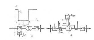
The no-load losses of the transformer are determined when creating a certain mode. To do this, the current supply to all windings is stopped. They remain open. After this, the circuits are supplied with electricity. It is determined only on the first circuit. The equipment must operate under the voltage that is set by the manufacturer during its production.
Currents flow through the primary circuit of a power, welding or other installation, which are called XX. Their value is no more than 3-9% of the indicator specified by the manufacturer. In this case, there is no electricity on the secondary circuit winding. In the primary circuit, current produces magnetic flux. It crosses the turns of both windings. In this case, an EMF of self-induction occurs on the primary circuit and mutual induction on the secondary winding.
For example, the open-circuit voltage of a low- and medium-power welding transformer represents the mutual induction emf.
Measurement approach
Measuring no-load losses can be done in two aspects. They are called steel and copper losses. The second indicator indicates heat dissipation in the windings (they begin to heat up). During the experiment this figure is very small. Therefore they are neglected.
Data on the loss of no-load current of the transformer is presented in the form of a table. It calculates parameters for steel of certain grades and thickness. The no-load current of a transformer is considered in terms of power, which is created in the magnetic flux and is called steel loss. It is spent on heating sheets made of a special alloy. They are isolated from each other by a varnish coating. When creating such magnetic drives, the welding method is not used.
The essence of measurement
If for some reason the insulating layer between the plates of the magnetic drive is broken, eddy currents increase between them. At the same time, the system begins to heat up. The varnish layer is gradually destroyed. Losses during operation of the installation increase, its performance characteristics deteriorate.
In this case, power losses in steel increase . When calculating these characteristics in idle mode, it is possible to identify any disturbances in the operation of the unit. It is for this reason that the corresponding calculation is made.
How is the idle test performed?
When conducting an idle test, it becomes possible to determine the following characteristics of the unit:
- transformation ratio;
- power loss in steel;
- parameters of the magnetizing branch in the equivalent circuit.
For the experiment, a rated load is applied to the device.
Also read: What is the difference between a transformer and an autotransformer?
When conducting an idle test and calculating characteristics based on this technique, it is necessary to take into account the type of device.
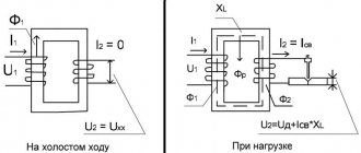
In this state, the transformer has zero useful power due to the absence of electric current at the output coil. The applied load is converted into heat loss on the input coil I02×r1 and magnetic core loss Pm. Due to the insignificance of heat losses at the input, they are not taken into account in most cases. Therefore, the total value of no-load losses is determined by the magnetic component.
The following are the features of calculating characteristics for various types of transformers.
For single phase transformer
The no-load test for a single-phase transformer is carried out with the connection:
- voltmeters on the primary and secondary coils;
- wattmeter on the primary winding;
- ammeter at the input.
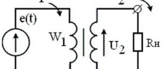
The devices are connected according to the following scheme:
To determine the no-load current Iо, use an ammeter reading. It is compared with the rated current value using the following formula, resulting in a percentage:
Iо% = I0×100/I10.
To determine the transformation ratio k, determine the value of the rated voltage U1н according to the readings of the voltmeter V1 connected to the input. Then, using the voltmeter V2 at the output, the value of the rated voltage U2O is taken.
The coefficient is calculated using the formula:
K = w1/w2 = U1н/ U2О.
The amount of loss is the sum of the electrical and magnetic components:
P0 = I02×r1 + I02×r0.
But, if we neglect electrical losses, the first part of the sum can be excluded from the formula. However, an insignificant amount of electrical losses is typical only for low-power equipment. Therefore, when calculating the characteristics of powerful units, this part of the formula should be taken into account.
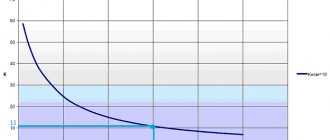
No-load losses for transformers with a power of 30-2500 kVA
For three-phase transformer
Three-phase units are tested according to a similar scheme. But the voltage is supplied separately for each phase, with the appropriate installation of voltmeters. You will need 6 units of them. You can conduct an experiment with one device, connecting it to the required points one by one.
Also read: Purpose of voltage indicators
When the rated voltage of the winding electric current is more than 6 kV, 380 V is supplied for testing. The high-voltage mode for conducting the experiment will not allow achieving the necessary accuracy for determining the indicators. In addition to accuracy, the low-voltage mode ensures safety.
The following scheme applies:
The operation of the device in idle mode is determined by its magnetic system. If we are talking about a type of device similar to a single-phase transformer or an armored rod system, the closure of the third harmonic component for each phase will occur separately, with a value increasing to 20 percent of the active magnetic flux.
As a result, an additional EMF arises with a fairly high rate - up to 60 percent of the main one. There is a danger of damage to the insulating layer of the coating with the possibility of failure of the device.
It is preferable to use a three-rod system, when one of the components will not pass through the core, with a circuit through air or another medium (for example, oil), with low magnetic permeability. In such a situation, the development of a large additional EMF, leading to serious distortions, will not occur.
For welding transformer
For welding transformers, idling is one of the modes of their constant use in operation. During welding in operating mode, the second winding is short-circuited between the electrode and the metal of the part. As a result, the edges melt and a permanent connection is formed.
After finishing work, the electrical circuit is broken and the unit goes into idle mode. If the secondary circuit is open, the voltage in it corresponds to the EMF value. This component of the power flow is separated from the main one and is closed through the air.
To avoid danger to humans when the machine is idling, the voltage value should not exceed 46 V. Considering that in some models the value of these characteristics exceeds the specified value, reaching 70 V, the welding unit is equipped with a built-in performance limiter for idle mode.
Also read: What is the absorption coefficient of a transformer
The blocking is activated within a time not exceeding 1 second from the moment the operating mode is interrupted. An additional protective measure is a grounding device for the welding unit housing.
Video: measuring no-load current
Transformation ratio
When determining the operation of an installation, a concept such as transformation ratio is used. Its formula is presented below:
K = E1/E2 = W1/W2
It follows that the voltage on the secondary circuit will be determined by the ratio of the number of turns. To be able to regulate the output electricity, a special device is built into the design of the installation. It switches the number of turns on the primary circuit. This is an antsapf.
To conduct the experiment at idle, the regulator is placed in the middle position. In this case, the coefficient is measured.
Single-phase devices
To carry out the presented experiment, when using a step-down or step-up household unit, the presented coefficient is taken into account. In this case, two voltmeters are used. The first device is connected to the primary winding. Accordingly, the second voltmeter is connected to the secondary circuit.
The input impedance of the measuring instruments must correspond to the nominal characteristics of the installation. It can operate in buck or boost mode. Therefore, if it is necessary to carry out repair work, not only the supply of low but also high voltage is measured on it.
Three-phase devices
For three-phase units, during the experiment, indicators on all circuits are examined. In this case, you will need to use 6 voltmeters at once. You can use one device that will be connected in turn to all measurement points.
If the value set by the manufacturer on the primary winding exceeds 6 kV, a current of 380 V is supplied to it. When measuring in high-voltage mode, it is impossible to determine indicators with the required accuracy class. Therefore, measurements are carried out in low voltage mode. It is safe.
Applying the coefficient
During the measurement process, the trunnion is moved to all positions specified by the manufacturer. In this case, the transformation coefficient is measured. This allows you to determine the presence of a short circuit in the turns.
If the phase readings have a scatter during measurements of more than 2%, as well as their decrease in comparison with previous data, this indicates deviations in the operation of the unit. In the first case, a short circuit is detected in the system, and in the second, a violation of the insulation of the windings is detected. The unit may not operate correctly.
Such facts require confirmation. For example, this could be a resistance measurement. An increase in the spread of the coefficient indicators can be influenced by an increase in the resistance between the contacts of the axle. When switching frequently, this situation occurs.
Loss measurement
Losses in the magnetic drive are measured exclusively when using a powerful installation. In this case, you can take for calculations a reduced voltage, which is connected to the primary circuit through a wattmeter. This is a direct measurement method.
When taking into account the readings of a voltmeter or ammeter, you will need to multiply their powers by each other. This is an indirect method. However, the result has a certain error. The distortion occurs due to the inability to take into account the power factor in such a calculation. This is the cone angle that is formed in a vector circuit between voltage and current. In idle mode, an angle of 90º appears between them.
Measures to reduce no-load current
The current when the transformer is in idle mode occurs due to the design features of the core. A ferromagnetic material exposed to an alternating current electric field is characterized by the induction of eddy inductive Foucault currents, which cause heating of the element.
To reduce eddy currents, the core is not made as a single piece, but is assembled from a package of thin plates. The plates are insulated from each other. An additional measure is to change the properties of the material itself, which makes it possible to increase the threshold of magnetic saturation.
To prevent a break in the magnetic flux with the appearance of a stray field, the plates are carefully adjusted during the recruitment process. Individual elements are ground to obtain a smooth, perfectly fitting surface.
Losses are also reduced due to more complete filling of the magnetic circuit window. This allows us to ensure optimal weight and dimensions of the unit.
Idling of a transformer is a mode in which important characteristics can be calculated. This is carried out for equipment in operation and at the design stage.
Source