The flow of current in an electrical circuit is carried out through conductors, in the direction from the source to the consumers. Most of these circuits use copper wires and electrical receivers in a given quantity, having different resistances. Depending on the tasks performed, electrical circuits use serial and parallel connections of conductors. In some cases, both types of connections can be used, then this option will be called mixed. Each circuit has its own characteristics and differences, so they must be taken into account in advance when designing circuits.
Series connection of conductors
In electrical engineering, the series and parallel connection of conductors in an electrical circuit is of great importance. Among them, a series connection scheme of conductors is often used, which assumes the same connection of consumers. In this case, inclusion in the circuit is performed one after another in order of priority. That is, the beginning of one consumer is connected to the end of another using wires, without any branches.
The properties of such an electrical circuit can be considered using the example of sections of a circuit with two loads. The current, voltage and resistance on each of them should be designated respectively as I1, U1, R1 and I2, U2, R2. As a result, relations were obtained that express the relationship between quantities as follows: I = I1 = I2, U = U1 + U2, R = R1 + R2. The data obtained are confirmed in practice by taking measurements with an ammeter and a voltmeter of the corresponding sections.
Thus, the series connection of conductors has the following individual features:
- The current strength in all parts of the circuit will be the same.
- The total voltage of the circuit is the sum of the voltages in each section.
- The total resistance includes the resistance of each individual conductor.
These ratios are suitable for any number of conductors connected in series. The total resistance value is always higher than the resistance of any individual conductor. This is due to an increase in their total length when connected in series, which also leads to an increase in resistance.
Ohm's law for a circuit section
One of the key electrical laws can be called Ohm's law for a section of a circuit. It is this law that explains the differences that exist for parallel and series connections of conductors.
It is formulated this way:
The current strength in a conductor is directly proportional to the voltage applied to its ends and inversely proportional to the resistance of the conductor.
It is written by the following formula:
I = U/R , where
I – current strength, (A);
U – voltage, (V);
R – electrical resistance, (Ohm).
Parallel connection of conductors
In electrical networks, conductors can be connected in various ways: in series, in parallel and in combination. Among them, a parallel connection is an option when the conductors at the starting and ending points are connected to each other. Thus, the beginnings and ends of the loads are connected together, and the loads themselves are located parallel to each other. An electrical circuit may contain two, three or more conductors connected in parallel.
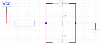
If we consider a series and parallel connection, the current strength in the latter can be studied using the following circuit. Take two incandescent lamps that have the same resistance and are connected in parallel. For monitoring, each light bulb is connected to its own ammeter. In addition, another ammeter is used to monitor the total current in the circuit. The test circuit is supplemented by a power source and a key.
After closing the key, you need to monitor the readings of the measuring instruments. The ammeter on lamp No. 1 will show the current I1, and on lamp No. 2 the current I2. The general ammeter shows the current value equal to the sum of the currents of individual, parallel-connected circuits: I = I1 + I2. Unlike a series connection, if one of the bulbs burns out, the other will function normally. Therefore, parallel connection of devices is used in home electrical networks.
Mixed compound
A mixed connection is a connection that is a combination of serial and parallel connections. To find the equivalent resistance, you need to “collapse” the circuit by alternately transforming parallel and serial sections of the circuit.
First, let's find the equivalent resistance for the parallel section of the circuit, and then add to it the remaining resistance R3. It should be understood that after the conversion, the equivalent resistance R1R2 and resistor R3 are connected in series.
So, that leaves the most interesting and most complex connection of conductors.
Laws of series and parallel connection of conductors
These laws concerning both types of conductor connections have been partially discussed earlier.
For a clearer understanding and perception in a practical sense, series and parallel connection of conductors, formulas should be considered in a certain sequence:
- A series connection assumes the same current in each conductor: I = I1 = I2.
- Ohm's law explains the parallel and series connection of conductors in each case in its own way. For example, with a series connection, the voltages on all conductors will be equal to each other: U1 = IR1, U2 = IR2. In addition, with a series connection, the voltage is the sum of the voltages of each conductor: U = U1 + U2 = I(R1 + R2) = IR.
- The total resistance of a circuit in a series connection consists of the sum of the resistances of all individual conductors, regardless of their number.
- With a parallel connection, the voltage of the entire circuit is equal to the voltage on each of the conductors: U1 = U2 = U.
- The total current measured in the entire circuit is equal to the sum of the currents flowing through all conductors connected in parallel: I = I1 + I2.
Difference between serial and parallel connection, advantages and disadvantages
The fundamental differences between serial and parallel connections of conductors according to key electrical parameters are shown in the table:
| Parameter/connection type | Sequential | Parallel |
| Electrical resistance | Equals the sum of the electrical resistances of all electrical consumers. | Less than the electrical resistance value of each individual connected electrical appliance. |
| Voltage | Equals the total voltage of all electrical consumers. | The same value in all sections of the electrical circuit. |
| Current strength | The same value in all sections of the electrical circuit. | Equals the total value of the currents on each of the devices. |
Due to its characteristics, each type of chain assembly has its own advantages and disadvantages. This allows you to use these methods to solve various electrical problems.
Pros and cons of serial connection
The main advantages of electrical circuits made of series-connected devices are their following features:
- ease of design and construction of the circuit;
- low cost of equipment;
- the ability to connect devices designed for a lower operating voltage compared to the rated network voltage;
- performing the function of current regulation - ensures uniform loads on all devices.
However, this method of electrical circuit layout also has serious disadvantages . The main one is the unreliability of a chain of series-connected conductors. If any of the connected devices fails, the entire circuit is switched off.
In addition, the disadvantage is that the voltage decreases with an increase in the number of connected consumers. An example would be a series connection of several lamps. The more lighting fixtures connected to the power source in this way, the less bright the light they will produce.
Pros and cons of parallel connection
When using parallel connection of conductors, the following set of advantages is provided:
- stability on electrical appliances, regardless of their number;
- the ability to turn on or off individual sections at the right time without disrupting the operation of the entire electrical circuit;
- reliability – if one or more components fail, the electrical circuit itself continues to operate.
The disadvantage is a more complex calculation and complex circuit, the use of which increases the cost of completing the electrical network.
It is not allowed to connect devices with a rated operating voltage less than the network voltage. Parallel connection of batteries with different voltage values is associated with the flow of current into the battery with a lower value, which can cause accelerated wear of the battery.
Application of parallel and serial connections in electrical engineering
Parallel connection is actively used for installing wiring and circuits in various types of electrical equipment and devices. It makes it possible to connect electrical devices to the power grid independently of each other.
A serial connection is used when you need to enable and disable certain devices. It is according to this scheme that switches and toggle switches are connected . The circuit is also well suited in cases where it is necessary to form an electrical circuit of consumers with a low rated voltage.
When connecting capacitors in parallel, the total capacitance is equal to the sum of the capacitances of each semiconductor. If a series connection of capacitors is used, the resulting capacitance is halved. This property is also used in the formation of electrical circuits.
Series connection of conductors: video
Parallel connection of conductors: video
How to use knowledge about the features of parallel and serial connections
Probably the most important question that a student faces is why do he need to know all this ?
Everything is quite simple here. Knowing these parameters, you can easily assemble the desired circuit. For example, let's imagine that we want to connect two batteries, each with a voltage of 6 V, to connect a car LED rated at 12 V. How to connect the batteries? If in parallel, we get increased capacity and a voltage of 6 V. The diode will not “smoke.” If we use a serial connection, then at the output we will have the sum of 6 V + 6 V = 12 V. The problem is solved. There are many, many such examples that can be given.
Another question is how to calculate other parameters (capacitance, power, inductance) when connecting conductors in series and parallel.
For example, if we connect 5 capacitors in series, how can we find out the total capacitance of this circuit? Of course, you can, again, memorize the formulas. In practice, you will forget them as soon as you stop solving such problems. Therefore, it is much more important to keep in mind the physical definition of capacitance, and from it derive a specific particular case, remembering that with a series connection, the current strength is always the same, and the voltage is summed up.
Problem on serial connection of conductors
Condition. Two lamps and a resistor are connected in a circuit one behind the other. The total voltage is 110 V and the current is 12 A. What is the value of the resistor if each lamp is rated at 40 V?
Solution. Since a series connection is considered, the formulas of its laws are known. You just need to apply them correctly. Start by finding out the voltage across the resistor. To do this, you need to subtract the voltage of one lamp twice from the total. It turns out 30 V.
Now that two quantities are known, U and I (the second of them is given in the condition, since the total current is equal to the current in each series consumer), we can calculate the resistance of the resistor using Ohm’s law. It turns out to be equal to 2.5 ohms.
Answer. The resistor's resistance is 2.5 ohms.