Scope of application
You should not assume that the scope of application of phase indicators is limited only to industrial installations. Yes, until recently, devices of this class were used by electricians working in enterprises whose technological processes are based on equipment with high-performance electrical machines.
But now they are building large cottages and townhouses with a complex power supply system. Even in comfortable apartments, the number of electricity consumers has increased to such an extent that connecting to single-phase power becomes impossible. But connecting a three-phase electric meter correctly without observing the phase order will not work. Any error will cause this meter to operate incorrectly, which will result in an unreasonable increase in electricity bills.
In addition, in areas where it is impossible to connect a central water supply, where water supply is required using powerful three-phase electric pumps, improper connection of the equipment will cause long-term failure. Therefore, the use of a phase indicator in this area is considered mandatory.
Phase indicator operating instructions
Just 15 years ago, electricians had only a few types of phase indicators at their disposal, but now their number is much larger.
If we roll back and remember the Soviet Union, then the most popular phase indicator there was the I517M, proven by work and time.
This device is small in size and can fit in the palm of a person. Its main difference from other devices is the sensitivity when alternating phases.
How to choose a phase meter - review, purpose, principle of operation, scope of application + instructions for use with photosHow to make a transformer with your own hands - step-by-step instructions, diagram, drawings, list of materials + photo of a finished homemade transformer
Which hidden wiring detector is better? TOP 10 best manufacturers with photos and descriptions
To learn more about all its features, you need to read the instructions for use. But to put it briefly, the operating instructions look like this:
When working with this device, you should always inspect it. This precaution is necessary.
When working with a phase indicator, a special output with a winding is used.If the integrity of the device is compromised, then with 100% probability you will receive a very strong electric shock, which subsequently entails serious health problems.
Next, the indicator disk rotates, which in turn indicates the correct order of phase alternation.
Electrician in the house
Author: admin, 05 Feb 2015
In this article we will look at the operation and diagrams of phase indicators, I will also tell you how to make a simple phase indicator with your own hands, why you need a phase indicator, how to use it and types of phase indicators.
Phase indicators are devices designed to determine the order of phase alternation. Please note - it is the order of alternation, i.e. not a single phase indicator will show you where phase A, B and C are, it will only show direct (A-B-C, B-C-A, C-A-B) or reverse (A-C-B, C-B -A, B-A-C) phase alternation. But in most cases this is enough, for example, if you connect a new input to the electrical panel and make the same alternation as the old input, then all the electric motors will rotate in the right direction.
For phasing, for example, transformers, you will need to check the phases of the same name with a simple two-pole indicator. On ones with different names it will glow, on ones with the same name it won’t. But let's return to the phase indicators.
The industry produces a large number of different models of phase indicators, the most common brands were FU-2, EI5001 (analogous to I517m), VC-805... Instructions for using phase indicators EI5001 and VC-805 can be downloaded on the regulatory documents page.
Let's look at the FU-2 phase indicator shown in the picture above. The phase indicator has three terminals designated according to the phases “A”, “B” and “C”. Three alligator clips, or three probes, are connected to these clips; for convenience, electricians mark them with colored electrical tape in accordance with the color marking of the phases according to the PUE. (A - yellow, B - green, C - red).
They use the FU-2 phase indicator as follows : connect the “crocodiles” to the busbars or exposed phase wires, after which they briefly press the button located on the left side of the housing. If the white disk with slots rotates in the direction indicated by the arrow next to the disk (clockwise), then the order of phase alternation is direct. If the disk rotates against the arrow, then the phase sequence is reversed.
If you don’t have a phase indicator on hand, you can make a simple phase indicator with your own hands. To do this, we need 4 incandescent lamps of 220V, 25-60 W, sockets for them and a non-polar capacitor with a capacity of 2-3 μF.
Circuit of the simplest phase indicator
The diagram shows:
- L1-L4 - incandescent lamps 220V, 25-60 W.
- C1 - non-polar capacitor 2-3 µF, 500V.
- A, B, C - probes corresponding to phases A, B, C.
Circuit operation
If, when the probes touch the phases, the lamps of phase “A” (L1, L2) light up at full incandescence, and the lamps of phase “B” (L2, L3) light up at half-incandescence, then the order of phase alternation is direct.
Scheme at work
Of course, such a phase indicator turns out to be quite bulky and inconvenient, so let’s consider another phase indicator circuit, somewhat more complicated, but much smaller.
It is possible, in principle, to modify this phase indicator by replacing the chains of lamps with chains of a series-connected quenching resistor and a light bulb from a flashlight, or by adapting LEDs.
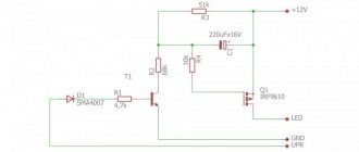
Phase indicator circuit on a thyristor
phase indicator on a thyristor
The diagram shows:
- R1 - resistor C5-35(PEV) 5 W, 1.8 kOhm.
- R2 - MLT-1 resistor, 10 kOhm.
- D1 - diode KD105V.
- VS1 - thyristor KU202N.
- L1 - lamp МН26-0.12.
Circuit details
Resistors can be of any brand with a value close to the specified one. R1 for a power dissipation of at least 5 W (depending on the lamp used), R2 for a power of at least 1 W.
Diode D1 can be taken from brand KD209.
The thyristor can be replaced with T112-10-5, T112-25-10.
Circuit operation
Terminal “0” is connected to zero, Terminals “A” and “B” are connected to any two phases. If the light bulb glows brightly, it means the terminals are connected to the same phases “A” and “B”, but if the light bulb lights up dimly or does not light up at all (can be adjusted by selecting the value of R1), then the terminals are connected in reverse.
Without going into details, I will say that such operation of the circuit is due to different opening angles of the thyristor; if you are interested, you can “rummage” on the Internet.
It will be interesting to read:
Battery charger
Capacitor tester
DIY extension cord
Category: Useful devices
Power factor adjustment
Most of the operation of the device falls on approaching cos units. If you studied well at school and didn't skip Physics classes, then you probably know about these units.
Technological maps in construction - what is it?- How to fix a laptop that won't charge
Insulated dielectric screwdrivers up to 1000V - tips on how to choose the best manufacturer
When the indicators of these units decrease, there will be a corresponding decrease in the power needed to heat the electrical equipment. The safest power factor is 0.90 units in inductive form.
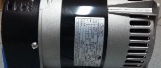
Electrodynamic phase meters
Often such devices are also called electromagnetic. Their operating principle is based on a simple chain of ratiometric devices that determine the slightest phase shifts.
Electromagnetic phase meters are a simple structure consisting of two aluminum frames, between which a high-sensitivity electrical wire passes.
It is worth paying attention to the fact that the angle between the frames is 65 degrees.
When working with a phase meter, the electrician pays attention to changes in the operation of the device. They are the ones that indicate the direction of the phase shift. A photo of a phase indicator on an electromagnet can be found freely available on the Internet.
Dielectric insulated tool for work - which one is better to choose? Review of manufacturers, photos + video- Properties, scope of application of Paroc basalt insulation
- Mitsubishi Electric: company history
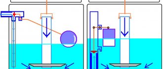
Principle of operation
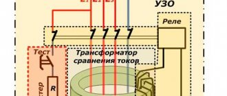
Let's look at the example of panel phase indicators such as Ts1425 and Ts425.1. The phase indicator consists of a unified measuring mechanism of the magnetoelectric system and a converter-rectifier.
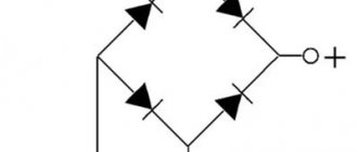
The current flowing through the frame of the measuring mechanism is the difference between two currents rectified by bridges V1 and V2. With direct phase order, the current rectified by bridge V2 is approximately twice as large as the current rectified by bridge V1. In this case, the total current through the frame of the measuring mechanism causes the moving system with the pointer to deviate to the right from the middle mark in the direction of the arrow on the dial.
If the phase order is reversed, the current rectified by bridge V1 will be greater than the current rectified by bridge V2, and the pointer will deviate in the opposite direction.
Three-phase EMF system
Very often on various forums people are interested in the EMF system. This system is a set of three-phase networks that depend on each other. The system is used in car engines, as well as many of the most primitive electrical appliances. More details about it can be found in the relevant literature and drawings.
Photo of phase indicators
Did you like the article? Share

0