Spark gaps IP
Spark gaps IP are designed to protect the reinforcement of supports and foundations from the flow of stray currents and the passage of currents into the track circuit during an insulation breakdown on the contact network of railways and high-voltage longitudinal power supply lines passing along the supports. They serve to protect underground structures from electrical corrosion by currents flowing from the rails through the grounding conductors and foundation reinforcement into the ground in accordance with the rail-ground potentials and resistances, which depend mainly on the traction current and have different zones along the track (with a cathode zone near the substation ). The amount of current flowing from the support depends on the rail-ground resistance.
Spark gaps under normal conditions are cut into the grounding conductor, isolating the supports from the rails. When a high voltage (800 V) hits the support, a breakdown of the spark gap occurs and solid grounding occurs on the rail. Structurally, spark gaps can be single- or multiple-action.
Repeatable spark gap IP-3
The spark gap IP-3 has an insulation between the terminals with the insert removed of 10 MΩ and provides the passage of shock current with one-way power supply with a pulse of 7 - 9 kA and a flow time of 0.04 - 0.06 s; with double-sided supply - with the same impulse and subsequent flow for 0.3 s, as well as a single automatic reclosure with an interval of 6 - 10 s.
Technical characteristics of IP-3
- DC breakdown voltage - from 1.3 to 1.7 kV;
- Overall dimensions, mm, no more: diameter - 62 mm, height - 252 mm;
- Weight, no more - 0.85 kg
- Type of climatic modification - UHL1 from minus 60°С to plus 40°С.
Spark gap IPM-62
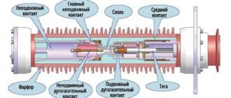
The spark gap IPM-62 consists of a housing with a lid, inside of which there is a removable insert with two contact washers and mica spacers between them. To prevent welding of the removable insert to the lid when the gap is broken, a screen in the form of a carbolite ring is provided. The breakdown voltage of such a spark gap is 800 - 1200 V. On supports with horn gaps, two spark gaps are installed if the wire of the grounded horn is not isolated from the support.
IPM are designed for operation in temperate climates.
Technical characteristics of IPM-62
- Breakdown voltage - 0.8 - 1.2 kV
- Diameter - 65 mm
- Height - 260 mm
- Weight - 1 kg
As an IPM, it is recommended to use the gas-discharge protection device GRPZ-1U, which has improved parameters of moisture protection and corrosion resistance, and also has better technical characteristics compared to IPM-62, shown in the table:
Technical characteristics of GRPZ-1U and IPM-62
| Parameter | GRPZ-1U | IPM-62 |
| Breakdown voltage, V | 1400-1700 | 800-1200 |
| Breakdown current amplitude, kA | Up to 9 | 5-6 |
| Pulse duration, ms | 40 | 100 |
| Number of breakdowns | 12 | 1 |
Spark gap IPZ-1 with double washers
The spark gap IPZ-1 is designed to protect railway supports from overvoltage.
Currently, the railway uses spark gaps made of cast iron with a safety insert made of 10 parts to isolate railway supports from the rails. The body of the spark gap IPZ-1 is made of electrical material, and the internal insert consists of 5 parts.
The modernized design of the spark gap made it possible to replace cast iron with modern materials with higher electrical properties, and the dimensions of the product have changed significantly. The spark gap has become more compact and lighter.
Technical characteristics of IPZ-1
TU 3185-777-05770820-01
- DC breakdown voltage - 0.8-1.2 kV
- Overall dimensions, no more: diameter 46 mm, height - 210 mm, spanner size S1 - 41 mm, S2 - 22 mm
- Weight, no more than - 0.25 kg
The insulation between the output pins with the insulating gasket removed must withstand a test voltage of 2 kV industrial frequency.
Output pins, made of calibrated steel 35 according to GOST 1050-88, must be protected from corrosion by a protective coating. Coating - galvanizing with chromium plating from 9 to 12 microns according to GOST 9.305-84.
The surfaces of the housings are underfilled, cracks and delaminations are not allowed. The housings may have a uniform, unequal color, depending on the color of the polyamide granules.
To prevent destruction of the spark gap by excess gas pressure when it is triggered, holes must be provided in the housing, which must be filled with silicone sealant.
The specified service life is 10 years. The insulating gasket must be replaced after each spark gap operation.
Possible modifications of spark gaps IP:
- IPM-Ch – with a cast iron lid;
- IPM-S – with a cover made of sheet steel;
- IMP-62M,
- IPM 62-2 - cast iron spark gap (body made of cast iron);
- IPM 62-1 - spark steel gap (steel stamping body);
- IPV-TsNII-62 with a varistor (therefore its impulse characteristics are similar to those of an arrester).
Spark gaps and horn gaps
⇐ PreviousPage 15 of 16Next ⇒Spark gaps are the simplest and cheapest surge protection device; currently they are rarely used. In networks with a voltage of 3..35 kV they can be made in the form of horns that help stretch and extinguish the arc due to electrodynamic forces and heat flows. In networks up to 35 kV, the length of the protective gap is small, and to prevent birds from closing the gap, additional spark gaps are created in the grounding slopes.
The spark gap parameters are given in table. 16.2 (according to [7]).
Table 16.2
| Parameter | Rated voltage, kV |
| Main gap length, mm | |
| Length of additional gap, mm | — |
| Breakdown voltage amplitude 50 Hz, kV ampl. | |
| Pulse breakdown voltage, kV (for negative pulse) |
Spark gaps have a number of disadvantages , the main of which are the following:
- triggering of spark gaps leads to a short circuit, which must be turned off by switches; during the transient process of voltage cutting, overvoltages may occur on the longitudinal insulation of transformers, reactors and electrical machines;
— a large statistical spread of breakdown voltages makes it difficult to coordinate insulation;
- the volt-second characteristic of the spark gap, due to the sharp inhomogeneity of the field, has a rise in the region of small times corresponding to lightning overvoltages, and the protected insulation may remain unprotected (Fig. 16.1).
Rice. 16.1. Volt-second characteristics of insulation (1) and spark gap with a sharply non-uniform field (2)
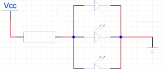
Horn gaps, which are quite widely used on the contact network, are made either with one spark gap or with two spark gaps (Fig. 16.2). The current “Rules for the design and technical operation of a contact network” require the use of horn gaps with two spark gaps.
Rice. 16.2. Horn arresters used on contact networks
The parameters of the horn arresters are given in table. 16.3 (according to work [2]).
Table 16.3
| Parameter | With one spark. in between | With two spark gaps | |
| Voltage k/s, kV | 3.3 | 3.3 | |
| Distance, mm | 10..11 | 4,5..5,5 | 40..50 |
| Breakdown voltage amplitude 50 Hz, kV ampl. | |||
| Pulse breakdown voltage, kV | |||
| Maximum current at which the arc can go out on its own, kA | — | ||
| Arc extinguishing time, s | 0,25..0,6 | 0,2..0,6 | — |
The arc extinguishing ability of a horn arrester is highly dependent on wind speed and direction. The arc goes out faster when the wind is directed perpendicular to the plane of the spark gap.
Tubular arresters
Tubular arresters (Fig. 16.3) are a type of spark gaps, supplemented by a device for forced arc extinguishing, which is made in the form of a tube made of gas-generating material (vinyl plastic or less durable fiber bakelite).
The protective function of a tubular spark gap is performed in the same way as a simple spark gap, with the same disadvantages; The accompanying short-circuit current arc is switched off due to intense gas emission from the tube at an elevated arc temperature. A specific disadvantage of the tubular arrester is the presence of an exhaust zone of the arrester.
Rice. 16.3. Design of a tubular spark gap and volt-second characteristics of the RTF-35/0.8-5 spark gap at l
2=60 mm (1),
l
2=40 mm (2), horn arrester 2x50 mm (3)
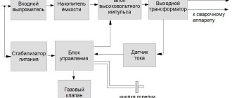
In accordance with the functions performed, the tubular arrester is characterized by two groups of parameters . The first group includes rated voltage, power frequency breakdown voltage, pulse breakdown voltage and volt-second characteristic. The second group includes the lower and upper limits of switched currents.
The main application of tubular arresters is to protect approaches to substations, protect equipment of low-power substations 3-10 kV and protect AC contact networks.
Valve arresters
Valve arresters are another type of spark gap, characterized by a weak inhomogeneity of the electric field and a nonlinear resistor for extinguishing the arc. The protective function of a valve-type arrester is performed in the same way as a simple spark gap, but due to the homogeneity of the electric field, the volt-second characteristic of the arrester is significantly better than that of a tubular arrester, and the statistical spread of breakdown voltages is smaller.
The resulting short circuit is disconnected using a nonlinear resistor connected in series with the spark gap; The resistance of this resistor is high at operating voltage and decreases sharply at higher voltages.
The simplest single gap of a valve arrester is shown in Fig. 16.4a. The gap is made up of two brass electrodes separated by a micanite washer.
Rice. 16.4. A single spark gap with a stationary arc (a) and a view of the volt-second characteristic of a spark gap with a multiple spark gap (b)
Single gaps are connected in series with each other to improve arc extinction, which is unstable in a small gap with cold electrodes. In a multiple spark gap, however, there is an uneven distribution of voltage across individual gaps, similar to a string of insulators, which leads to a decrease in the breakdown voltage at short times of the order of 2-4 μs (Fig. 16.4b).
The group of characteristics of a valve arrester, which determines its protective function, is composed of the following characteristics:
- Rated voltage;
— the highest permissible long-term voltage on the arrester;
— breakdown voltage at a frequency of 50 Hz (usually effective value);
- the remaining voltage across the resistor at a certain pulse current (from 5 to 14 kA, depending on the type of arrester), called the coordination current (Fig. 16.5).
Rice. 16.5. Current-voltage characteristic of the valve-gap resistor (a) and the voltage across the valve-gap when it is triggered (b)
The shutdown function is characterized by a quenching voltage - this is the highest industrial frequency voltage on the spark gap, at which the accompanying current (quenching current) is reliably interrupted.
Another characteristic of the arrester is its throughput, that is, the minimum number of normalized current pulses that the arrester must withstand without significantly changing its properties. This number is usually 20.
Thus, both the protective function and the short circuit breaking are determined by both the spark gap and the nonlinear resistor.
⇐ Previous15Next ⇒
What makes your dreams come true? One hundred percent, unshakable confidence in your...
Live by the rule: IS THERE NOT MUCH THING IN THE WORLD EXISTING? It is no coincidence that I emphasize that the space in your head is limited, but there is a lot of information around, and that your right...
What does the IS operation and maintenance department do? Responsible for the safety of data (copying schedules, copying, etc.)…
Conflicts in family life. How can I change this? It is rare that a marriage and relationship exists without conflict and tension. Everyone goes through this...
Didn't find what you were looking for? Use Google search on the site: