Electrical diagrams. Types of circuits
Hello Habr! More often, articles provide colorful pictures instead of electrical diagrams, which causes disputes in the comments. In this regard, I decided to write a short educational article on the types of electrical circuits classified in the Unified System of Design Documentation (ESKD)
.
Throughout the entire article I will rely on the ESKD. Let's consider GOST 2.701-2008 Unified System of Design Documentation (ESKD). Scheme. Types and types. General requirements for implementation
. This GOST introduces the concepts:
- type of circuit
- a classification grouping of circuits, distinguished according to the principle of operation, the composition of the product and the connections between its components; - scheme type
- a classification grouping distinguished based on their main purpose.
Let's immediately agree that we will have only one type of circuit - an electrical circuit (E)
. Let's figure out what types of circuits are described in this GOST.
| Circuit type | Definition | Circuit type code |
| Structural diagram | A document defining the main functional parts of the product, their purpose and relationships | 1 |
| Functional diagram | A document explaining the processes occurring in individual functional circuits of the product (installation) or the product (installation) as a whole | 2 |
| Schematic diagram (complete) | A document that defines the full composition of elements and the relationships between them and, as a rule, gives a complete (detailed) understanding of the principles of operation of the product (installation) | 3 |
| Connection diagram (installation) | A document showing the connections of the component parts of the product (installation) and defining the wires, harnesses, cables or pipelines by which these connections are made, as well as the places of their connections and input (connectors, boards, clamps, etc.) | 4 |
| Connection diagram | Document showing external connections of the product | 5 |
| General scheme | A document defining the components of the complex and their connections to each other at the site of operation | 6 |
| Layout diagram | A document defining the relative location of the components of the product (installation), and, if necessary, also bundles (wires, cables), pipelines, optical fibers, etc. | 7 |
| Combined scheme | A document containing elements of different types of circuits of the same type | 0 |
| Note - The names of the types of circuits indicated in brackets are established for electrical circuits of power structures. | ||
Next, we will consider each type of circuit in more detail as applied to electrical circuits.
Main document: GOST 2.702-2011 Unified system of design documentation (ESKD).
Rules for executing electrical circuits .
So, what is it and what do these electrical circuits “eat” with? GOST 2.702-2011 will give us the answer: Electrical diagram
is a document containing, in the form of conventional images or symbols, the components of a product operating with the help of electrical energy, and their interconnections
.
Depending on the main purpose, electrical circuits are divided into the following types:
Electrical structural diagram (E1)
The block diagram shows all the main functional parts of the product (elements, devices and functional groups) and the main relationships between them. The graphical construction of the diagram should provide the best idea of the sequence of interaction of functional parts in the product. On the interconnection lines, it is recommended to use arrows to indicate the direction of the processes occurring in the product. An example of an electrical structural diagram:
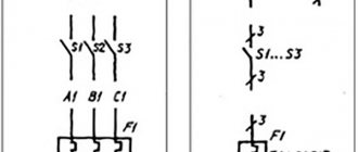
Electrical functional diagram (E2)
A functional diagram depicts the functional parts of a product (elements, devices and functional groups) participating in the process illustrated by the diagram, and the connections between these parts. The graphical construction of the diagram should give the most visual representation of the sequence of processes illustrated by the diagram. An example of an electrical functional diagram:
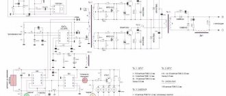
Electrical circuit diagram (complete) (E3)
The circuit diagram shows all the electrical elements or devices necessary for the implementation and control of established electrical processes in the product, all the electrical connections between them, as well as the electrical elements (connectors, clamps, etc.) that terminate the input and output circuits. The diagram may depict connecting and mounting elements installed in the product for structural reasons. The circuits are performed for products in the off position. An example of an electrical circuit diagram:
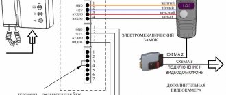
Electrical connection diagram (installation) (E4)
The connection diagram should show all devices and elements included in the product, their input and output elements (connectors, boards, clamps, etc.), as well as connections between these devices and elements. The location of graphic symbols of devices and elements on the diagram should approximately correspond to the actual placement of elements and devices in the product. The arrangement of images of input and output elements or terminals within graphic symbols and devices or elements should approximately correspond to their actual placement in the device or element. Example of electrical connection diagram:
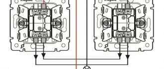
Electrical connection diagram (E5)
The connection diagram must show the product, its input and output elements (connectors, clamps, etc.) and the ends of wires and cables (stranded wires, electrical cords) connected to them for external installation, near which data on connecting the product (characteristics) should be placed external circuits and (or) addresses). The placement of images of input and output elements inside the graphic designation of the product should approximately correspond to their actual placement in the product. The diagram should indicate the positional designations of the input and output elements assigned to them on the circuit diagram of the product. Example of electrical connection diagram:
General electrical circuit (E6)
The general diagram shows the devices and elements included in the complex, as well as the wires, bundles and cables (stranded wires, electrical cords) connecting these devices and elements. The location of graphic symbols of devices and elements on the diagram should approximately correspond to the actual placement of elements and devices in the product. Example of a general electrical diagram:
Electrical layout diagram (E7)
The layout diagram shows the component parts of the product, and, if necessary, the connections between them - the structure, room or area on which these components will be located. Example of electrical layout:
Combined electrical circuit (E0)
This type of diagram shows various types that are combined with each other in one drawing. An example of a combined electrical circuit:
PS
This is my first article on Habré, don’t judge strictly.
Schematic electrical diagram.
D - Grounding symbol. For a complex product, several functional diagrams are developed that explain the processes occurring under various intended operating modes. For example, if a multi-contact relay is depicted, then the used contacts are drawn longer, and the unused contacts are drawn shorter.
The total power of the MV units connected to the switchgear must correspond to the maximum power supplied to the network of this voltage; using block step-up autotransformers, which simultaneously provide communication between the switchgear of two increased voltages Fig. Examples of UGO in functional diagrams Below is a drawing depicting the main components of automation systems.
If the design of a device element and its documentation do not indicate the designations of the contact pins, then it is permissible to conditionally assign designations to them on the diagram, repeating them later in the corresponding design documents. The controller system allows you to have all types of control of electric motors: starting, speed control, reverse, braking, stopping and, in addition, protecting the motors from overload and decrease or disappearance of voltage in the supply network.
Now let's look at each scheme in more detail.
However, the motor remains switched on as power to the contactor coil is maintained through the auxiliary contact K1. Recommended forms of the connection table are shown in Fig. Schemes for direct starting of a motor with contactor control. How to read electrical diagrams. Lesson #6
Functional diagram images
The difference between a functional diagram and a structural diagram is a more detailed description of the functions of existing elements, parts and parts. The presented graphics are designed in such a way that they clearly demonstrate the sequence of all ongoing processes. To display the components, combined or spaced methods are used.
All images presented on functional diagrams are divided into several categories:
- Functional groups correspond to the symbols used in circuit diagrams. If an image in the form of a rectangle is used, in this case the name of this group is applied.
- Each element or individual part is assigned a conventional graphic designation in the form of alphanumeric characters, similar to circuit diagrams.
- Devices shown as a rectangle must match the reference designation assigned on the circuit diagram. The marking consists of the name and type or document regulating the use of this device. This information is located inside a rectangle. Similar documents can be indicated for devices represented by graphical symbols. Any abbreviations and other conventional names are applied to the fields of the diagram near the rectangle.
External connection E5
In the drawing, it is necessary first of all to indicate the product itself, its input and output components (couplings, clamps, etc.) and the contacts of cords and external installation cables connected to them, near which information about the connection itself is located.
The constituent parts of the plan are shown as quadrangles, and the input and output parts are shown as lines, segments and dotted lines. It is allowed to use simpler notation to construct the diagram.
How the harness connection is clearly indicated
Note! Connectors, clamps and other components are positioned in the same way as they appear on the product itself.
Introductory details can be placed in the form of iconic graphic symbols. The drawing must indicate the input, output or output parts that are present on the product. If these components are not included, then conventional symbols are used in the diagram.
It is allowed to write an explanation and name next to all components. As well as the necessary data from the documentation on the product. Cable products and cords are shown as separate lines. It is allowed to use markings for cable products, but its explanation is written strictly in the margins (name, cross-sectional area, power, number of cores inside).
You might be interested in Connecting ops-1
E6 GOST
2.2. Types of conductor connections
In practice, the connection of conductors can be done in one of four ways:
2.2.1. Sequential
A serial electrical connection of conductors is used if it is necessary to provide the same current strength in all sections of the circuit. An example is an old Christmas tree garland. It also demonstrates the disadvantage of such a connection - when one light bulb burns out (circuit failure), all the others go out.
2.2.2. Parallel
Electrical connections of conductors in parallel are the most common, since in this case an electric current of the same voltage is supplied to all elements of the circuit. But the current strength is different. But if any one element of the circuit malfunctions, this will not affect the operation of the others. An example would be connecting all electrical appliances in an apartment or house. So, turning off the overhead light in the room does not affect the operation of the TV, etc.
2.2.3. Mixed
A mixed connection of an electrical circuit means the presence in it of both series and parallel connections of conductors.