Design and operating principle
Transformer - the name of the word comes from the Latin transformare, which means to transform. The generally accepted definition for it is as follows: a transformer is a device that, using the phenomenon of electromagnetic induction, is capable of changing the amplitude of the voltage without changing the shape and frequency of the signal.
A transformer is an electrical device that reduces or increases alternating electrical voltage. Such transformers are called step-down or step-up transformers. It should be noted that there are also devices that leave the magnitude of the sinusoidal signal unchanged; they are called galvanic or throttle.
Any transformer in its design contains the following components:
- magnetic circuit (core);
- windings;
- frame for winding arrangement;
- insulator;
- various additional elements (brackets for fastening, strips for contact output, etc.).
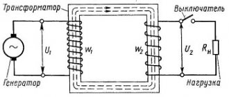
The transformer in its design has two or more windings with inductive coupling. They are produced in both wire and tape types and are always covered with a layer of insulation. The windings are fixed to a magnetic core made of soft ferromagnetic material. The primary winding is connected to the voltage source, and the secondary winding to the load.
The general principle of operation of the device, regardless of its type and purpose, is as follows. An alternating signal is supplied to the primary winding of the device, which leads to the appearance of alternating current in it. This current, in turn, induces an alternating magnetic field in the core, under the influence of which an alternating electromotive force (EMF) occurs in the windings. When a load is connected to the secondary winding, alternating current begins to flow through it. The winding to which the signal is applied is called the primary. The winding connected to the load is called the secondary.
According to the cooling method, toroidal devices are divided into those using air and liquid cooling. In addition, there are transformers with combined cooling - liquid-air. The main technical parameters of the device include:
- Input voltage value: the permissible voltage value supplied to the primary.
- The magnitude of the output voltage. Determined by the transformation ratio.
- Transformation type. Exists with increasing or decreasing signal level.
- Number of phases. Depending on the network in which transformers are used, they are divided into single-phase or three-phase.
- Number of windings. There are two-winding or multi-winding devices.
The main parameters of the device include: rated power and transformation ratio. The unit of power is volt-ampere (VA). The transformation ratio shows the ratio of voltage levels at the input of a device to its output. Its value is directly proportional to the ratio of the number of turns of the primary to the secondary.
Winding a toroidal transformer through the eyes of a practitioner. Finishing and fastening
This article does not claim to be a bestseller of popular science literature, but rather a guide for beginners. The article describes the winding process itself, and not its calculation.
Sooner or later, in the practice of every radio amateur, the question arises of what to power this or that device. The most common ULF powers are 2*100 or 2*200. Therefore, the best option is a “donut” with 150 watts of overall power, in the first case you need one for 2 channels, in the other a couple for dual mono. The toroidal transformer has the best size-power ratio, high efficiency, and minimal interference. This is why audiophiles love them so much. Let us consider the winding process of this type of transformers in more detail.
The main thing that a person who winds a transformer should know and understand is:
- wire length (number of turns) is voltage;
- the cross-section of the conductor is the current with which it can be loaded;
- if the number of turns in the primary circuit is small, then this is excess heating of the wire;
- if the overall power is insufficient (more than possible is consumed), this is again heat;
- overheating of the transformer leads to reduced reliability.
So, what is needed for winding:
- Transformer iron in the shape of a torus (later I will write where to get it);
- Lacquer wire (a winding wire is needed for the transformer winding);
- Masking tape (paper);
- PVA glue;
- Fabric tape or wicker tape;
- Pieces of wire in insulation;
- And lastly, but most importantly, is desire.
TRANSFORMER HARDWARE
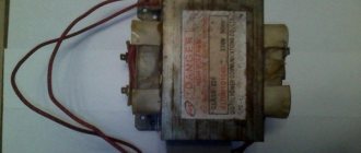
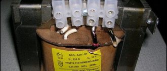
I won’t talk about how to calculate the power of iron; there are already a lot of articles for this... Calculating power is difficult from a practical point of view, since the grade of steel and the quality of its production are not known. Therefore, two cores with the same overall mass have different parameters. Let's consider an example of winding a core on an already “spent” core. One of the easiest to obtain cores, the quality of which is worthy of attention. The core is from the Soviet stabilizer "Ukraine-2" (SN-315). At one time, a lot of them burned down, and you can get such a device on the market for 20 UAH... We are interested in the torus. This donut is wound with aluminum varnish, we mercilessly wind it up (or bite it), we need a core (carefully so as not to damage the core). Aluminum wire can be used for other purposes (twisting brooms or wires), or in my case, I melt it down for other purposes (making radiators). After winding, a beautiful core is obtained with dimensions of 96-54-32 mm, respectively, outer, inner diameter and height. Below is an example of such a core (Fig. 1). The overall power of such a core is at least 120 watts (tested in practice).
Before winding, it is necessary to prepare the iron for winding. If you look at the corners of the transformer, you will notice that they are at an angle of 90 degrees, at these points the wire will bend and the varnish will peel off, so that this would not be necessary to process the corners with a file, rounding them as much as possible (I understand that it is lazy, but it is necessary). The minimum radius of the circle is 3mm. In Fig. 1 you can see that the corners have already been processed, and the torus is ready for winding. A little trick: when processing corners with a file, you must avoid licking the steel so that the layers remain open to each other! To do this, move the file along the direction of the transformer tape. After processing, I recommend checking the corners for the closure of the layers and finishing them with a fine file.
In order to isolate the core from the winding, it is necessary to insulate it with FABRIC insulating tape (or a boiler impregnated with paraffin wax). It is better to use electrical tape with a width of about 25 mm (Fig. 2), then there will be maximum coverage of the metal in one layer, which allows you to save space in the window. We do not seal the end of the winding (read further).
After these operations, the core is ready for winding and we move on to the next step.
VARNISH PIPE
I call a varnish wire an electrical conductor whose insulation is made of varnish (culturally, winding or winding wire). There are different brands of PEV, PEV-2, PET-155 and others. I recommend using PEV-2, rich orange color. Also, a very dark-looking wire (PEL), the color of rotten cherry, performed very well; it has a thick layer of insulation, which allows it to be used for high-voltage transformers (more than 500V). For example, a PEV-2 wire with a diameter of 1.6 mm has an insulation thickness of about 0.06-0.07 mm, and a “black” wire is 0.1-0.11 mm.
Calculating the wire cross-section is a very interesting process. There is a lot of literature on this topic on the Internet, and I will not write about all sorts of calculations and subtleties (Google to help). Depending on the current density you choose, the wire cross-section will be different. The main thing that is required is the correct power ratio. It is necessary that the power of the secondary winding does not exceed the capacity of the primary. As you know, the efficiency of transformers in the form of a torus is very high and equals about 97%, therefore, when winding a torus with a power of 200 watts, 6 watts of losses is a trifle that can be neglected. We assume that the power of the primary winding is greater than or equal to the power of the sum of all secondary windings.
Calculation example. You need to wind the transformer. The primary winding is designed for 220V. There are two secondary windings of 28V each. The diameter of the primary winding wire is 0.6 mm in varnish. The thickness of the varnish is about 0.06mm, and the “clean” diameter of the primary winding wire is about 0.54mm. We substitute the area of the circle into the formula and get a cross section of 0.228 mm2 (if you don’t know how I calculated this, then buy an amplifier and don’t bother). And so, based on the proportion, we get 220V/28V*2=3.92, which means that the secondary winding should have a cross-section 3.92 times thicker than the primary winding. As you can see, I did not use power and, accordingly, current density. Everyone takes the current density that they consider correct (for myself I take 4A/mm2, and my thoughts are confirmed by a real trance test, which I will describe further).
For the core described above, it is better to use a primary wire of at least 0.6 mm in diameter. A wire of this cross-section and the required length can be found in old tube TVs, in the form of demagnetization loops. There are always people on the market who buy old TVs (“junk dealers”), and you can find the necessary wire from them. We have two types of loops on the market: small and large, smaller for 20 UAH, large for 50.
Small in diameter, 2 of these are used in TVs. The diameter of such a half-demagnetization loop is about 40-50 cm, the cross-section of the conductor is somewhere around 0.6 mm. With high-quality installation, this loop is enough to wind the primary winding of one torus with a margin of a couple of meters.
If you use a large loop, then the length of the wire is literally one and a half times longer than the small one, so it is more profitable to buy small loops. Sometimes you come across a loop from a tube, color TV, the length of the wire in such a loop is similar, but the cross-section of the wire can reach 0.7 mm. If you get one, you're lucky.
And so you found a demagnetization loop, usually it is wrapped in keeper fabric (rag strip), and on top with transparent tape or electrical tape. Near the wire terminals there is a joint where you can catch and carefully unwind the loop. There is no need to cut, saw off, or tear off the insulation; you can damage the wire; in addition, we will still need this insulation. After winding, we are left with a beautiful wire that can be used. Some people rewind the wire onto a “shuttle”, I personally don’t do that, why bend the wire once again if it’s already the right shape, besides, if you wind small tori, the shuttle will take up more space and may not fit through the window, and also damage the varnish . Before you start winding it, you need to make twists so that the wire does not move apart. In order to make twists, you need to take pieces of single-core wire (preferably in PVC insulation) 5-7 cm long. We wind the loop in a circle with a slightly tight step, then during winding, in order to add (unwind the wires) you will just need to twist this spring and the wire will separate (see photo Fig. 3).
Now our loop has one end on the outside, and the other somewhere inside, we need the outside one. Next, let's return to the iron, which we have already processed and wrapped with electrical tape or wicker. Remember, we didn’t seal the edge, that’s why (look at Fig. 4). On the side where the top of the trance will be (the terminals go up), at the corner of the torus we make a cut in the center of the insulating tape and thread the varnish pipe there already in the insulation; this will be the outlet for the beginning of the winding. Some recommend soldering a piece of flexible stranded wire in insulation and making such a tap. I’m not happy with this option because in this way I don’t know which wire is in the primary, and even ten years later I measured it with a micrometer and you know what you can reap from it, but with a tap, who knows what the cross-section is there. It's up to you though.
Let's make leads for the wire. The winding terminals must be “strengthened” with additional insulation. PVC insulation (Soviet white) is very suitable for these things, but insulation made from wire of the required cross-section is even better. You can use heat shrink, but it is better to use PVC or insulation because the former tends to bend in one place, which we really don’t need; we are trying to protect ourselves from this so that the wire does not break off. In order to tighten the insulation, I recommend taking a wire that has additional insulation in the form of a thread wrapped around the conductor. In this case, the thread does not create a strong bond between the PVC and copper and allows the insulation to be pulled together. To make it easier to tighten the wire, you need to bend it a little (at 45 degrees). I recommend “stretching” the insulation at a time and using it. (Fig.2).
Domestic winding wires
The most widely used are winding wires in enamel insulation based on high-strength synthetic varnishes with a temperature index (TI) in the range of 105...200. TI refers to the temperature of the wire at which its useful life is at least 20,000 hours.
Copper enameled wires with insulation based on oil varnishes (PEL) are produced with a core diameter of 0.002...2.5 mm. Such wires have high electrical insulating characteristics, which are practically independent of the external influence of elevated temperatures and humidity.
Wires of the PEL type are characterized by a greater dependence on the external influence of solvents, compared to wires with insulation based on synthetic varnishes. The PEL winding wire can be distinguished from others even by its external appearance - the enamel coating is close to black in color.
Copper wires of types PEV-1 and PEV-2 (available with a core diameter of 0.02...2.5 mm) have polyvinyl acetate insulation and are golden in color. Copper wires of types PEM-1 and PEM-2 (with the same diameter as PEV) and rectangular copper conductors PEMP (cross-section 1.4...20 mm2) have varnished insulation on polyvinyl-formal varnish. The index “2” in the corresponding designation of PEV and PEM wires characterizes two-layer insulation (increased thickness).
PEVT-1 and PEVT-2 are enameled wires with a temperature index of 120 (diameter 0.05...1.6 mm), they have insulation based on polyurethane varnish. Such wires are convenient to install. When soldering, it is not necessary to strip the varnished insulation and use fluxes. Regular POS-61 solder (or similar) and rosin are sufficient.
Enameled wires with insulation on a polyesteramide base PET-155 have a TI equal to 155. They are produced with conductors not only of round cross-section (diameter), but also of rectangular (PETP) type with a conductor diameter of 1.6-1.2 mm2. In terms of their parameters, PET wires are close to the PEVT type wires discussed above, but have higher resistance to heat and thermal shock. Therefore, winding wires of the types PEVT and PET, PETP can be especially often found in powerful transformers, including transformers for welding.
WINDING PROCESS
To wind the trance you will need 4-5 evenings and 2 hours of time, why at least 4 days you will understand later.
We have already run one end of the wire and pressed it. Then the most dreary winding begins. I recommend winding it like this. We take a trance (iron for now), put on a glove or take some rags made of natural fabric in our hand. We sit down on the sofa or bed, turn on a movie we’ve already seen or music (so as not to be too distracted), and start watching. We thread each turn into an iron ring. You need to wind it turn to turn from the inside (some people manage to wind it from the outside, I can’t imagine how).
Recommendations for the winding process
To make it easier to count the turns, it is better to group them into 5 or 10 turns. It is necessary to pull the wire not strictly perpendicular (dotted red line) to the tangent (pure red), but slightly inclined towards the winding (yellow), as if the inner part of the winding goes in front of the outer one (Fig. 5). In this way, the winding wire, when stretched, will itself be pressed against other already laid turns. If your wire is bent, it will not fit perfectly, so it must be as straight as possible; to do this, while winding it, you need to pull it strongly, thereby straightening it. That's why you need gloves or rags; if you don't use gloves, your fingers and palms get tired and sore very quickly. If you wind a wire with a cross-section of more than 1.5 mm (very difficult), then I recommend slightly bending the wire under tension for ease of straightening.
(My friend’s father winds 50 hertz welders, a secondary shredder lays 35 squares of copper with his hands perfectly evenly, so he bends 5 kopecks of Ukraine into a dumpling with his fingers).
During winding, the wire is inspected for flaws, especially in places of bending; if the varnish is broken, then carefully cover it with insulating lacquer or paint (in extreme cases, ordinary nail varnish).
When the layer has been wound to the end. Between layers it is necessary to make interlayer insulation. I'm lucky and I have some stash of varnished fabric, and the fabric is stretchy and impregnated with something sticky. If these stick to each other (formed), then it is very difficult to separate them. It makes my fingers stick together. This varnished fabric is an ideal insulator; in addition, the winding does not rattle even when overloaded. But very few people have this. The same functions of an insulator can be very well implemented using masking tape.
After we have wound the layer, we take it and insulate it with masking tape. We make strips about 15mm wide. And we initially wrap the trans with these strips to insulate the inside of the wire winding (from the inside of the donut). Then we isolate the gaps from the outside of the donut. As a result of insulation with adhesive tape, it turns out that the insulation from the inside, by applying layers, will become twice as thick, and from the outside it will be single. After wrapping it, you need to generously lubricate the torus with PVA glue, this is done so that the tape does not unwind, and it will also become stronger and seem solid. In addition, the glue will hold the windings so that they do not “buzz”. There is no need to spare glue, lubricate it with your finger and rub it in lightly. After which the torus needs to dry. I usually wind the torus in the evening, soak the layer with glue, and place the torus itself on a needle radiator for good air circulation. Overnight the torus dries and can be wound further. That's why a minimum of 4 pm is required for winding (4 pm - 4 layers). If necessary, you can speed up the drying process with a hairdryer. Let's wind the next layer... the winding process itself is similar and no different. At the end of the winding, we place the end of the winding in the same insulation as at the beginning of the winding. Then we secure the end of the winding with masking tape, insulate the winding with masking tape and impregnate it with glue.
There is another good option for insulating between layers. It will be very good if during winding you use baking paper (parchment) cut into the same strips and then wrapped. As a result, the trans will need to be soaked, but in reality, a mixture of 50:50 paraffin:wax, respectively, should be cooked in a steam bath. We take a steam bath into a saucepan, fill it with water and set it to boil (we need steam). We place a container on top in which the transformer and paraffin wax are placed. We tie the transformer to a wire in advance, leaving the end (when the mixture flows behind this thread, you need to soak the transformer like a tea bag in a cup). When you dip the transformer, you need to be careful so that drops of wax do not fall on the flame, it is very flammable!!! Previously, output transformers for tube ULFs were impregnated with exactly this “dissolution,” although other high-quality trances were also impregnated. When the mixture is heated, it has a very high fluidity, almost like water, as a result of which the paper becomes literally saturated with paraffin and wax. However, this option will not be initially effective if the trans is heated (warm) at a temperature of 50 degrees, the wax is already quite soft and will not restrain the wire from vibration of 50 Hz, although it will act as a dielectric. (True, it is precisely because of vibration and friction that the wires fray and a closed loop is obtained, which leads to damage during operation).
For pulse transformers, I recommend using paper + BF-2 glue as impregnation rather than tape. This adhesive is primarily used in the manufacture of speaker coils. But it also performed very well in a pulse transformer. With repeated overload, not the slightest squeak at the conversion frequency of 15 KHz. Unwinding the windings from the frame, they were removed with a cable 8 cores wide.
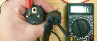
During winding, we periodically measure the no-load current; to do this, you need to connect the tester in series with the primary winding in ammeter mode (read the instructions for the tester). Measure the current x.x. You need to be very careful because it works from the network! To avoid any emergency situations, I recommend turning on a 220V light bulb in series with the primary, with a power of about 40W. The light bulb will light up if the number of turns is very small; if the trans is wound correctly, then it should only have a pink tint, which indicates a low current flowing through it. The transformer has large starting currents; at the moment the transformer starts, overloads can reach 160 times. Therefore, starting the transformer must be done not directly through the tester, but using a “jumper”, which you then open and the current begins to flow through the tester. The jumper can be implemented by simply shorting the tester probes, which are then opened. I will write below what the no-load current should be.
For transformers with low current consumption, it is recommended to use a 10 or 100 Ohm resistor (2-5W) which is connected in series with the primary winding. After measuring the voltage drop across the resistor, use Ohm's law to resample the current. This method is more preferable than the first, but at the same time more dangerous at high current consumption - the resistor turns into coal in a fraction of seconds!!!
About how to measure current x.x. I briefly told you what I wrote, now about the meanings. Current norm x.x. Everyone determines it individually for each trance, but usually the norm is up to 50 mA at 230V, although some say that 0.5A is normal. The lower the current the better! The lower the quiescent current, the more the current shape is x.x. looks like a sine. If you have current x.x. from 20-50 it’s tolerable, let’s say a C, from 10-20 it’s four, less than 10mA it’s clearly five. For small torics, the current will be small due to the high resistance of the primary winding, this must be taken into account! Although, how can I wind a toroid by hand with less than a hundred watts, this is an atrocity! The number of turns of the primary winding in them reaches a couple of thousand.
The transformer I wound according to my method has a current of x.x. equal to 11mA (with 4 layers of primary).
If you do everything sequentially, you will get something similar:
TESTING AND MEASUREMENT PROCESS
About how to measure current x.x. I briefly told you what I wrote, now about the meanings. Current norm x.x. each is determined individually for each trance, but usually the norm is up to 50 mA at 230V, although some say that 0.5A is normal. The lower the current the better! The lower the quiescent current, the more the current shape is x.x. looks like a sine. If you have current x.x. from 20-50 it’s tolerable, let’s say a C, from 10-20 it’s four, less than 10mA it’s clearly five. For small torics, the current will be small due to the high resistance of the primary winding, this must be taken into account! Although, how can I wind a toroid by hand with less than a hundred watts, this is an atrocity! The number of turns of the primary winding in them reaches a couple of thousand.
It will be very useful to look at the shape of the no-load current in the primary winding using an oscilloscope. BUT!! this must be done under very special conditions! For this, an isolating transformer (220/220V) is required, although the induction must be very low so as not to cause additional distortion of the “sine” shape. And also latr. I recommend doing this test item only to very experienced specialists, the consequences are fraught with burnout of the oscilloscope!!!
When using my winding parameters, I “removed” 150 watts from such a trance for several hours (there was no time longer).
We isolate the primary winding from the secondary.
After winding the required number of layers of the primary winding, we come to the moment of winding the secondary. It is necessary to isolate the primary winding from the secondary very carefully.
If the secondary winding suddenly burns out, the worst consequences are failure of the ULF. But if at this moment the secondary winding somehow “shorts” to the primary, then this is already a danger to life! Because the secondary winding of the transformer at the middle point is connected to the wuxia body, imagine that when you turn the volume control knob you get an electric shock?! It’s unpleasant, therefore, grounding in an outlet is not a desirable norm, it’s a necessity, if you value your health, I recommend paying special attention to this... (This was a small digression).
Based on the fact that sockets VERY rarely have REAL grounding, you need to isolate the primary winding from the secondary as much as possible. For this operation, you can use the already established method and use masking tape. BUT the layer thickness needs to be at least doubled, or better yet tripled. Moreover, impregnation with glue is necessary; the glue will add elasticity and an additional layer. A better option would be to use special electrical varnishes such as TsAPON (color is not important). In this case, we literally soak the torus in varnish, you can even soak it! The varnish will be more fluid if it is heated; when heated, the capon melts like water, and thereby saturates the windings well, insulating and securing them. Regarding the primary winding, these are some of the best measures, as for me even better than paraffin. If you are going to use impregnations, then it is logical that using any “yellow transformer” tape is contraindicated; a layer of tape simply will not allow it to leak deeper, unlike paper or varnished cloth. Regarding “fixing” and insulating the secondary winding with the help of varnishes, I am categorically against it (what if you need to rewind the secondary, this will not be possible, besides, the wound wire will only be used for scrap metal.)
If there is no varnish, and masking tape is not impressive. It would be a very good idea to insulate the windings with fluoroplastic, this material is a super insulator! In appearance it looks like a white, slightly transparent film (photo below).
The main feature is that it is thermally resistant to heat (from minus -268 to +260 degrees). When I need to increase the temperature of the soldering iron tip, I simply wrap it with fluoroplastic, preventing the “body” of the soldering iron from cooling). Such highlights can only be found in specialty stores, although there will also be J varnished fabric nearby, which is also very good. Not everyone has access to such assortments, but if you want... In this case, I recommend rummaging through the bins. Fluoroplastic of the shape we need can be obtained in FT type capacitors. If we carefully dismantle the aluminum casing of the capacitor, we will get a core (the capacitor itself) made of tightly wound fluoroplastic, which we need so much. From a 0.022 microfarad capacitor you can wind two pieces of one meter each. To insulate the primary we need about 5-6 meters. That is, we are looking for at least 3 capacitors. Fluoroplastic capacitors have very good sound, so think first before spoiling them.
Keep in mind that fluoroplastic will not allow the trance winding to become saturated like tape, so if you want to soak it with paraffin, do it before insulating the windings with fluoroplastic.
I’ll describe shielding the primary winding from the secondary a little later; this is more likely to be included in the section on higher matters.
Final finishing of the trans and its fastening.
I skip the moment of winding the secondary, because it is absolutely similar to the process of winding the primary. As for the final finishing, there are some points you need to understand.
A toroidal transformer is a closed magnetic circuit, the core tape is wound in a dense roll after being annealed in an oven under vacuum. Winding it is complicated by the need to thread the wire through the window. Its advantage is that the core itself is located inside without emitting unnecessary interference, because at the moment they are picked up by the trance secondary. Thus, the core of the trance - a rough piece of iron - is inside, and a soft copper wire exposed with a fragile varnish (a piece of iron) bravely protects it. The toroid body is very susceptible to external damage. A torus falling from a decent height can “kill” it with the help of short-circuit windings. Whereas trances such as PL or Sh-shaped iron, on the contrary, protect the secondary winding. In this way, it is much easier to secure the TS-nick because it can and should be compressed very strongly with metal ties in order to reduce the gap in the core, and thereby minimize losses and hum-vibrations of the plates. It is much more difficult to secure a toroid, or rather there are minimal options. Before making the final finishing of the trans, you need to clearly understand how the trans will be attached to the body.
And yet, what are the options for insulation and finishing:
As an option, you can use transparent tape in which the demagnetization loop was packaged (by the way, some loops were wrapped in fluoroplastic, check if you are lucky). The result is very beautiful donuts (you can see the winding and a beautiful wire). But the increased temperature of the transformer will soften the insulation, thereby reducing its strength level. But that's not the main thing! When you insulate the transformer with a “film”, the level of heat transfer drops significantly, and the torus can heat up more. I think everyone is trying to buy things from natural materials, trying to avoid synthetics, because the body “does not breathe” in it and a person sweats... so why should the torus endure. For these things, it is better to use keeper tape (sheet cut into J strips). In order for it to be even stronger, I soak it in that PVA glue before winding. Then I wrap the torus; during winding the excess is squeezed out. After drying, a nice, stiff rag frame is formed... If you suddenly need to unwind it, just soak it for a while. Treatment options (on an already wrapped transformer) with both alkyd and water-based paint, or special varnishes are also allowed.
What are the mounting options:
One of the obvious ways to fasten a torus is to fasten it with a bolt threaded through the center of the torus. When fastening in this way, keep in mind that through the bolt, and then the bottom of the case, then along the walls of the case, the top cover, a coil of cross-section may form that is simply crazy (depending on the diameter of the fastening bolt). Under no circumstances should you attach the torus to the bottom and top cover, you will form a closed loop and burn the torus!
In addition, interference will be generated in the gap between the fastener and the top cover since the bolt is iron (magnetic). The smaller the gap, the higher the level. It’s not uncommon to say that without a lid the ULF plays everything fine, there’s no background, I cover it with a lid and a crazy background appears. Interference is induced; to avoid such interference, it is necessary to use a fastening bolt made of diamagnetic materials, for example, brass has shown itself to work well... (but do not forget about the possibility of a coil forming through the body).
Now you need to somehow rest against the torus winding, while the contact area should be maximum to minimize the pressure on the wire. For these purposes, I use the rear washer and the core from the magnetic system of the speakers; all you need is to drill a hole in the core and cut the thread, and then you get a very good fastener (photo below).
You can also cut out a piece of PCB or gitinax with a thickness of 3 mm and shape it for maximum contact of the “washer” with the surface of the torus. You need to use a gasket between the “washer” and the body of the torus; for this, use rubber, the thickness of which should be at least twice as thick as the diameter of the secondary winding (guess why), with a bed both below and above. When making this washer, it is possible to provide for the installation of copper rivets in order to fix the terminals on the “terminal block”. If anyone doesn’t understand, there is a photo of such a design at the link.
The diameter of a pin or bolt threaded through the center of the torus is unlikely to correspond to the diameter of the window. In order for the donut not to fly on this bolt like a hoop on a ballerina, you must either wrap it with electrical tape (to the required diameter) or you can use thick cone-shaped rubber. Motorists can easily find this kind of rubber band, for example, a rubber band from a VAZ2107 jet stabilizer or shock absorber, it has the right shape and costs a penny.
It is not uncommon in factory versions to fill the window with a compound by inserting a bushing into which the torus is attached. In practice, this is not used by radio amateurs (usually) because, again, it is not possible to disassemble the torus without damaging the wire. At home, such a plug can be created using epoxy.
Another version of the “spider” fastener. In essence, the same washer cover is made, only in larger sizes. Its shape is usually a square cover made of iron or textolite, the edges protrude beyond the boundaries of the outer part of the transformer. Holes are drilled in these corners and bolted to the body, so you don't have to thread a bolt through the center and create an unfinished loop through the ULF body.
It would be VERY good to make an iron “pot with a lid” from thick steel (min. 2mm) for the toroid, in which to place the torus and fill it with a compound, such as paraffin or wax (or the same epoxy resin), although after epoxy it will not be disassembled. This solves not only the problem of fastening, but also shielding from interference. (I have a photo of a similar design lying around on my computer; I don’t remember the author, but I think he won’t be offended).
A little about shielding.
It would be very good to place a shielding winding between the primary and secondary windings. Ideally, this winding should practically cover all visible parts of the toroid, blocking the magnetic fluxes on the way from the core (primary winding) to the secondary. One end of the shielding winding should be “in the air”, and the other should be connected to the amplifier housing (sometimes through a resistor of up to 10 ohms). The first end can be well insulated and left inside the torus. The second one, the one that is connected to the ground of the housing, is brought out using a multi-core flexible wire.
Ideally, winding should be done with copper tape about 15-20mm wide, which is insulated on both sides with varnished fabric, electrical tape or fluoroplastic, or you can use masking tape, but very carefully so as not to tear or make microcracks (both in the tape and in the insulator), which will break through with voltage. Shielding in this way takes up a lot of space and creates a lot of voids, which impair heat transfer, adding hum and “in vain” moving the secondary away from the core. It will be “more” economical if you wind the screen with a wire with a diameter of about 0.6 mm. But if the core is visible, then be sure that the interference will pass through these “windows”, that is, either we wind it as needed very tightly in several layers, or we don’t do empty work! If possible, you can make such a screen, it will definitely be worse!
It is much better to shield the transformer after winding, that is, when the transformer is completely wound (Although, to be honest, you need to divide interference by class and type, and separately consider methods of dealing with them). Ideally, in this case, it would be to use permalloy rather than copper tape. Although if they look at you with brick eyes when you hear the word fluoroplastic, then you can dream about permalloy ;). It is very good to wrap the transformer in several layers of transformer iron; iron from any transformer is suitable for these purposes. (I use steel from an old 2-amp lath core).
Here the torus is shielded using a transformer tape, placed in a metal cover and boiled in paraffin, the current is x.x. 1.5 mA, primary coils over 2500 turns, interlayer fluoroplastic, with sequential paraffin welding. I made it in a mug + transformer steel, it turned out very well (see above)! This toroid was used to work in a preamplifier.
It’s not worth making a pot out of aluminum; it won’t protect you from anything. It needs to be made of thick steel (at least 2mm), and it’s also very good to additionally shield the inside with copper (sheet about 1mm thick). Although I didn’t do such things myself (from copper), authoritative people advised me.
In conclusion about interference from tori, I will say that toroids very rarely generate interference on equipment, while a peculiarity has been noticed that the toroids that generate noise are those that are not home-wired and have a high current. or increased induction... Therefore, if you are not greedy and wind the toroid with a low magnetic induction (increase the number of turns per volt), then you are unlikely to encounter the problem of interference from the transformer.
It is planned to supplement the article with such “highlights”... very briefly for now...
Internal resistance.
All transformers and energy sources (power supplies) have such an abstract parameter as internal resistance. What does it mean?! In the case of a transformer, this resistance will be equal to the active resistance of the windings. When you connect a load to the trans, the flowing current and the resistance of the windings create a voltage drop. In order for the voltage drop to be minimal, it is necessary to increase the cross-section of the conductor (reducing its resistance). But at the same time, it is necessary to take into account this fact during operation, that the overall power of the windings will be higher than the overall power of the core, carefully so as not to overload the primary.
Sectional winding.
Low induction.
Implicit coil.
Shielding and types of interference.
PS My first article and not yet finished, please don’t throw tomatoes at me... There’s no time to finish, I’m posting what I’ve already dashed off a long time ago... Now this bagel is successfully working in Natalie 2012EA, you can look for a photo in the corresponding thread, and here’s the link
Tags:
- power unit
- Transformer
Current transformer
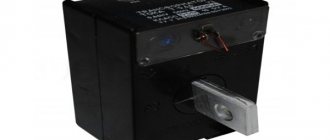
In addition to the standard type of voltage transformers, there is a special type called a current transformer. Its main purpose is to change the current value relative to its input. Another name for this type of device is current.
A current transformer is a measuring device designed to measure the strength of alternating current. Current devices are used when it is necessary to measure high current or to protect semiconductor devices from abnormal values that occur on the line.
The current device is no different in appearance from a voltage transformer; its differences are in the connection and the number of turns in the winding. The primary is made using one or a pair of turns. These turns are passed through a toroidal magnetic circuit, and it is through them that the current is measured. Current devices are made not only of the toroidal type, but can also be made on other types of cores. The main condition is that the wire being measured makes a full turn.
With this design, the secondary winding is shunted with a low-resistance resistance. In this case, the voltage on this winding should not be large, since during the passage of the highest currents the core will be in saturation mode.
In some cases, measurements are carried out on several conductors that are passed through the torus. Then the magnitude of the current will be proportional to the strength of the sum of the currents.
Calculation of product parameters
Before winding a toroidal transformer at home, you will need to calculate its values. To do this you need to know the source data. These include: the output voltage, the outer and inner diameter of the core.
The power of the device is determined by the product of the areas S and Sо, multiplied by the coefficient: P=1.9* S * Sоk.
The cross-sectional area is calculated using the formula: S=h*(Dd)/2, where:
- S - cross-sectional area;
- h - height of the structure;
- D - outer diameter;
- d is the internal diameter.
To calculate the window area, the formula is used: Sok=3.14*d2/4.
The number of turns in the secondary winding is equal to the product W2=U2*50/Sok.
Next, it remains to calculate the number of turns in the primary. For this, the expression is used: W1=(Uin*W2)/Uout, where Uin is the input voltage, and Uout is the voltage at the output of the device.
This calculation method can be applied to almost any type of toroidal transformer. But for the calculation of some products there is its own methodology.
Welding device
This type of transformer is characterized by a high output current. The maximum current and voltage are used as input parameters. For example, for a device with a welding current of 200 amperes and a voltage of 50 volts, the calculation is as follows:
Manufacturing of a toroidal core
Toroidal transformers contain a complex core in their design. Transformer steel is considered the best material for its manufacture. In order to make the core of a toroidal transformer you need to use steel tape. It must be rolled into a roll, which will have the shape of a Thor. If you already have such a form, then no problems should arise.
If the value of the internal diameter d is insufficient, then part of the tape must be unwinded. As a result, both diameters will increase and the entire surface area will increase. True, this may reduce your cross-sectional area.
You can also find a good ready-made core on a laboratory autotransformer. You should rewind its windings. Instrument transformers have a simpler core.
Another method for manufacturing a toroidal core is the use of plates from a faulty industrial transformer. First, you will need to make a hoop from these fasteners. Its diameter should be 26 cm. The plates must be gradually inserted inside this hoop. Make sure that they do not unwind.
If the toroidal transformer reaches the required cross-section, then its magnetic circuit is ready. To increase S you need to make two toroids. They must be the same size. Their edges will need to be rounded with a file. You need to make two special rings and two strips for Thor from cardboard. After applying them, all elements should be wrapped with insulating tape. Now your magnetic circuit is ready.
DIY winding machine
One possible option is to make a machine equipped with an adjustable stacker and a thread counter, using the principle of a bicycle wheel.
The wheel is placed on a pin in the wall, and its rim is equipped with a rubber ring. In order to put the core on the rim, you will first need to cut it and then fasten it again, obtaining a solid circle. Having wound the required length of wire around it, one end of it is connected to a core freely located on the rim. The coil moves along the rim in complete circles, as a result of which the wire is laid on the frame. In this case, a bicycle counter is used to count revolutions.
Creating a more advanced device will require the use of stepper motors with positioning of their position. For this, microcontrollers and an electronic counter are used. Such design requires certain skills in radio electronics.
Originally posted 2018-07-04 07:14:26.