Home » Electrical installation » Electrical panels » Lighting panels
The lighting board (LSB) is designed to receive and distribute electrical energy up to 380 Volts with a frequency of 50 Hz. Typically, boards are installed in residential, administrative or other types of buildings. Thanks to the installation of such boards, it is possible to provide protection against overloads and short circuit currents.
SCHO
In this article we looked at the features and design of lighting boards. You will also learn how to install lighting panels yourself.
ShchO classification
In modern lighting panels, manufacturers install special devices for protection against current leakage, elements of automation, control and monitoring. DIN rails should be used to mount the elements. The following materials are used for the ShchO body:
- Metal.
Metal lighting board
- Non-flammable plastic.
Plastic SCHO
Metal cases are usually used for shields that will later be installed on the street. Such shields will have high IP protection from the influence of environmental factors. To extend the service life of a metal shield, you need to use paint and varnish coatings. Due to high safety, such shields are now installed at all sites where there is increased danger. In addition, metal shields have a special fastening for connecting the grounding wire.
ShchO made of non-flammable plastic have an aesthetic appearance and are suitable for installation indoors. The plastic of such shields does not spread fire at all and does not require grounding. Depending on the type of installation, such boards can be:
- mounted;
- built-in
Hanging structures can be used for production workshops or auxiliary premises. Recessed lighting panels have an attractive appearance and are suitable for installation in residential buildings, where a lot of attention is paid to aesthetic issues.
Shield construction
A lighting panel is a compact metal (or plastic) cabinet, painted with powder paints and has a wall-mounted (sometimes built-in) design. Inside the shield contains an “N” bus, a “PE” protective grounding bus and mounting rails on which 16 or 25 ampere circuit breakers are mounted, as well as protective circuit breakers (RCDs).
For built-in versions, lighting electrical panels have IP30 protection. In the mounted version, the protection complies with IP31, IP54 standards.
Design and equipment
If we look at the design in more detail, then we can understand that it provides a distribution panel on which control elements for switching devices will be located:
- various automation elements;
- automatic switches of outgoing lines;
- automatic input switches.
Manufacturers today produce a variety of dimensions of SCHOs, the number of connected lighting lines, as well as power. Ease of installation can be achieved using a DIN rail.
Lighting board design
Most switchboards are equipped with a special door that prevents unauthorized access to switching devices. Using additional devices, you can set programs that turn the lighting on and off at a specified time. This helps to save electrical energy and maximize automation of the shutdown process.
To monitor the insulation of lighting networks and prevent fires, a variety of insulation leakage monitoring devices have recently been used. Special devices promptly disconnect the damaged electrical section without disrupting normally functioning sections of the electrical circuit.
Lighting panels OSCHV series: general characteristics
Lighting panels OSCHV (lighting panel with a switch) are similar to other electrical lighting panels in design and purpose.
| Type | Rated current of the input circuit breaker, (A) | Number and rated current of outgoing circuit breakers, (A) | Degree of protection | Installation method | Rice. |
| OSCHV-6(16)UHL4 | 40 | 6×16 | IP31 | on the wall | 8.1, 8.7 |
| OSCHV-6(25)UHL4 | 63 | 6×25 | |||
| OSCHV-12(16)UHL4 | 63 | 12×16 | 8.3, 8.8 | ||
| OSCHV-12(25)UHL4 | 100 | 12×25 | |||
| UOSCHV-6(16)UHL4 | 40 | 6×16 | IP31 from the facade | into a niche 230x330x90 | 8.4, 8.7 |
| UOSCHV-6(25)UHL4 | 63 | 6×25 | |||
| UOSCHV-12(16)UHL4 | 63 | 12×16 | into a niche 440x330x160 | 8.4, 8.8 | |
| UOSCHV-12(25)UHL4 | 100 | 12×25 | |||
| OSCHVG-6(16)UZ | 40 | 6×16 | IP54 | on the wall | 8.5, 8.7 |
| OSCHVG-6(25)UZ | 63 | 6×25 | |||
| OSCHVG-12(16)UZ | 63 | 12×16 | 8.6. 8.8 | ||
| OSCHVG-12(25)UZ | 100 | 12×25 |
Power supply panels for portable lighting devices
To power portable lamps in hazardous areas, a voltage of no more than 50 Volts should be used. To convert it, step-down transformers should be used. For such transformers, manufacturers produce special shields that contain:
- a step-down transformer that matches the required voltage;
- circuit breaker to protect the high voltage winding of the transformer;
- circuit breakers that will protect outlet lines;
- socket for connecting portable lamps.
YaTP-0.25
In addition to the standard socket, cable lines leading to stationary lamps can be connected to the housing. The supply voltage of lamps not higher than 12 volts can be used in the following cases:
- Cramped rooms.
- If the employee is in an uncomfortable position.
- There is constant contact between the employee and metal structures.
To save money, you can install a step-down transformer in a regular panel. To do this, select the appropriate transformer model and proceed with installation.
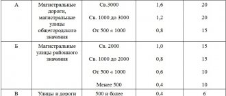
Calculation of perimeter security lighting system
The role of the security lighting system is not only to provide the lighting required for video surveillance at the protected facility (in particular, in the perimeter zone). A well-designed lighting system is also a powerful psychological factor that can prevent intrusion into a protected area. Firstly, good lighting greatly increases the risk of criminals being detected or apprehended. Secondly, lighting can demonstrate the strengths of the physical perimeter defense and even enhance the appearance of its reliability.
Light direction
Without dwelling on the psychological aspects, let's look at the technical side of the issue. Let's start with the simplest; how to direct light sources? It all depends on the relative position of the guarded line and the security point. If the security point is located in a protected area, then the lighting is directed outside the perimeter at a slight angle to the horizon. In this case, security officers clearly see potential intruders while remaining in the shadows themselves. If the security point is located outside the perimeter, the lighting is directed inside the protected area; perhaps directly to the object. Then the security will be clearly visible to any object trying to cross the brightly lit protected space. In any case, a well-implemented lighting system should ensure detection and constant visibility of the intruder from a distance of more than 200 m.
General requirements for security lighting
Once upon a time, security lighting systems had limited value - they allowed a person (watchman or sentry) to see what was happening at the protected site. Now the task of such systems is somewhat more complicated. Since lighting devices are most often installed in conjunction with a video surveillance system, their task is to ensure not just visibility in the protected area (which may include the fencing of the territory, the perimeter of the building, exclusion zone, patrol path (detour path), but optimal visibility taking into account the characteristics used CCTV cameras. From all of the above it follows that security lighting is not the same as ordinary street or, say, decorative lighting. It is designed separately, and there are very specific standards for it: documents of the Ministry of Internal Affairs, GOST 12.1.046-85 and Standard design solutions for the design of perimeter security lighting TPR9 88 GPKI "Spetsavtomatika". Accordingly, to connect the security lighting network, a separate group of lighting boards is used, which can be located in the security room or at a checkpoint (it is also possible to install a board on the external wall of the checkpoint on the side of the guarded territory). The security lighting system must be supplemented by emergency lighting, which is turned on automatically upon an alarm signal from the sensors of the perimeter security system. The inclusion can be controlled by a system for collecting and processing information. In this case, the zone from which the alarm signal came from, and sometimes two neighboring ones, is highlighted. For emergency lighting, CCD spotlights and DRL, PKN, PFS lamps are used, providing illumination from 10 to 50 lux. As for the security lighting system itself, according to the standards, it must provide illumination from 2 to 5 lux at night (usually 3–4 lux). This level of illumination is optimal for video surveillance of the perimeter and for urgent technical work (troubleshooting). Regardless of the time of day, the minimum illumination in the horizontal plane at ground level or in the vertical plane of the fence wall must be at least 0.5 lux. In this case, it is advisable to ensure that a strip of 6 to 15 meters inside the perimeter security zone is evenly illuminated. To achieve this, the lighting is calculated so that the cones of light overlap each other and form a continuous stripe. According to the regulations, light sources of security lighting systems mounted on fences must be located no higher than the level of the fence. The choice of design of devices is quite wide: these can be lifting, console lamps, spotlights, etc. The lighting source is either 220 V incandescent lamps or (together with black and white CCTV cameras) IR spotlights. To avoid mechanical damage, lamps must be covered with a metal mesh. The emergency lighting system from the security room is turned on.
Lighting calculation
When designing a security lighting system, in order to select the optimal number of lighting fixtures, the distance between them and the direction of the light cone, lighting calculations are carried out individually for each controlled area. To calculate the illumination from N sources at a certain point, it is necessary to know the luminous efficiency of the light sources; the distance between each of them and the illuminated object; angle of incidence of light. Lighting engineering calculations are based on the laws of propagation, reflection and absorption of radiation of various wavelengths (lamps are considered as point sources of light, and illuminated walls as secondary distributed sources). It is carried out for a group of characteristic points in several iterations, taking into account the sensitivity of television cameras. Illumination at a given point is calculated using the following formula:
Where: E – illumination at a given point, i – number of the light source, N – total number of light sources, I – luminous efficiency of the source, ? – angle of incidence of light from the source (the angle between the direction towards the light source and the perpendicular to the illuminated surface), R – distance from the light source to the selected point.
The luminous output of the source I (lm) is determined as follows:
Where ? (lm/W) – source luminous efficiency coefficient, P (W) – lamp power.
Coefficient ? depends on the type and power of the lamps. Here are some of its meanings.
| Lamp power | Luminous efficiency coefficient |
| Incandescent lamps | |
| 60 W | 12 lm/W |
| 150 W | 14 lm/W |
| High pressure mercury lamps | |
| 125 W | from 38 lm/W |
| 1000 W | up to 50 lm/W |
Calculation of illumination in the field of view of each camera according to formula (1) is carried out only for those light sources that are located between the camera and the illuminated object. In this case, we can neglect light sources located far from the video surveillance camera, since the light emitted by them is practically not perceived by the camera. Illumination is determined not only in the horizontal, but also in the vertical plane. When calculating illumination, it is worth considering that, as a rule, the object is illuminated from a different direction from where the camera is looking. In addition, to ensure that light reaches the camera only after reflection from the object, special devices are used: visors, hoods, etc.
Selection of light sources according to spectral characteristics
The spectral response of a CCD matrix, like that of the human eye, has a maximum at a wavelength of approximately 0.55 µm and can extend into the IR region (from 0.7 to 1.1 µm). Therefore, both gas-discharge lamps (most often high-pressure mercury lamps of the DRL type), which have a maximum spectral characteristic at a wavelength of about 0.5 microns (that is, close to the maximum characteristic of the CCD matrix), and incandescent lamps (they have a maximum accounts for 1.1 µm). However, calculation of effective illumination shows that incandescent lamps have low efficiency, therefore gas-discharge lamps, in particular DRLs, are more often used in security lighting systems. DRL lamps are marked with their rated power and red ratio. For example, DRL125(15), a DRL lamp with a power of 125 W and a red ratio of 15%. The red ratio rcr is a characteristic of a light source that shows its proximity to natural light. This value is calculated through the ratio of the red luminous flux to the total luminous flux of the light source (in percent).
Here S(?) is the spectral characteristic of radiation, K(?) is the spectral characteristic of vision. Gas-discharge lamps with a low red ratio (about 6%) provide optimal matching of the emission spectrum with vision characteristics. However, for CCD cameras, lamps with rcr = 12–15% are better suited, since they provide greater effective irradiation of the object. When using gas-discharge lamps, including DRLs, the stroboscopic effect should be taken into account. It occurs when the frame frequency of the camera and the power supply frequency of the lighting device are multiples and is expressed in image distortion. The strobe effect can be eliminated by synchronizing the frame rate with the phase of the supply voltage.
Calculating the contrast between object and background
The probability of detecting an intruder depends on its contrast relative to the background (protected object). The security lighting system should be designed to ensure maximum visibility of the object against the background, taking into account the sensitivity of CCTV cameras. As a rule, the camera's specifications indicate its sensitivity for high contrast values (about 85%). In real conditions, the contrast of the object relative to the background is much lower, due to which the sensitivity of the camera on the object is also reduced. This can be compensated for by additional, brighter lighting. Contrast K is calculated using the following formula:
where kо is the object reflection coefficient, kф is the background reflection coefficient.
Contrast of the object relative to the background
| K<0.2 | Small |
| 0,2 | Average |
| K>0.5 | Big |
Background
| kf<0.2 | Dark |
| 0.2< kf <0.4 | Average |
| kf >0.4 | Light |
Reflectance coefficients for some surfaces
| Green grass | 0,14 |
| Yellow grass | 0,22 |
| Sand | 0,15… 0,35 |
| Loamy soil | 0,15 |
| Concrete | 0,1… 0,19 |
| Light knitwear | 0,25… 0,35 |
| dark face | 0,19… 0,25 |
| Fair face | 0,35… 0,43 |
Calculation of contrast for different combinations of object and background shows that its average value in real conditions is approximately 15%, i.e. approximately 6 times lower than the value for which the cameras' specifications are indicated.
Infrared illumination
IR illumination is used in conjunction with black-and-white cameras and day/night cameras. Depending on the tasks assigned to the backlight, you can use IR emitters with visible or invisible glow. In the first case, the emitted wavelengths will range from 715 to 800 nm, in the second case - about 830 nm. Two types of illuminators are used for IR illumination: floodlights with halogen incandescent lamps and semiconductor IR illuminators. Halogen lamps (with a tungsten emitter) have a spectral maximum at a wavelength of 1 micron, which explains their fairly high efficiency. To suppress the visible part of the radiation spectrum, you can use dispersion filters based on IR glasses or (less commonly) interference filters.
Observation range
| IR illuminator power | Observation range |
| 500 W | 150–200 m |
| 300 W | 80–120 m |
| 50 W | 15–30 m |
| 20 W | 5–15 m |
When calculating IR illumination, it should be taken into account that different types of CCD matrices use only up to 15% of the light energy of the IR illuminator.
Using the light energy of an IR illuminator
| CCD type | Light filter | |
| 715 µm | 830 µm | |
| Line hyphen | 3 | 2 |
| ExView | 5 | 3 |
| Personnel transfer | 15 | 10 |
Semiconductor IR illuminators, compared to halogen lamps, have greater spectral brightness at the operating wavelength. Their operating range is entirely in the IR region of the spectrum with a central wavelength from 880 to 950 nm. The main difficulty when using such emitters is the effective removal of heat from the LED pad. Due to the complexity of calculations, when designing IR illumination, they usually rely on the range of possible maximum ranges indicated in the passport of each IR illuminator when using the illuminator in conjunction with a standard television camera.
External lighting panel
This device differs from a conventional panel only in that it contains devices for automatically or manually turning on the lighting. To ensure automatic control of outdoor lighting use:
- photo relay;
- motion sensors;
- sound sensors;
- annual relays;
- relays that control the switching on of lighting depending on the geographic coordinates of the place where it is installed.
Manual control mode may be required in the following cases:
- repair of the lighting network during the daytime;
- turning on the lighting when the relay is faulty;
- turning on the lighting when the conditions for relay operation are not met.
SCHO-400-6/1000-D
To switch to manual lighting control mode, use special switches. The sensors that are needed for control are located in places convenient for work. Manual control can be carried out in the following ways:
- One of the manual control key positions.
- Switch for external or internal installation.
- Push-button station.
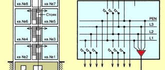
SCHO scheme
If the load that is connected to the switchboard exceeds the maximum permissible norm, then the connection is made through the starter. In this case, the relay will control the inclusion of the starter, and it, in turn, will turn on the lamps. Such a lighting board is marked as “SHCHNO”.
What are lighting shields used for?
A lighting board is a device for receiving and redistributing electric current along circuits that are used to power lighting. In fact, a lighting board differs from a distribution board only in that it controls the power supply to the external or internal lighting circuits of objects.
The task of the lighting board is to receive and distribute three-phase current with voltages up to 380 volts, as well as to protect the network from short-circuit currents and overloads. Unlike distribution panels, lighting panels are usually not equipped with electricity meters.
Structure of the lighting panel
According to GOST, lighting panels are produced by factories in the form of a ready-made, assembled structure that requires a minimum of manipulation during installation and connection. To install the shield, you need to fix the box on the wall, connect the outgoing lines of the lighting network, and then connect the incoming line.
A lighting panel can be a node element of several networks (external panel for several rooms), and an element that distributes current over several zones of one network (internal, apartment lighting panels). Each network or network section is connected to a separate switching group of the panel and has its own switch, fuse and emergency switch. An input load switch or an input circuit breaker can be installed on the input line of the panel, which allows you to disconnect the entire panel from the network. Thus, the design of the lighting panel provides both protection of the elements of the panel itself from loads and currents during a short circuit, and protection of each network zone connected to a separate switching group.
Types of lighting panels
Different models of lighting panels differ from each other primarily in the features of their external design. The internal, technical contents of the panels are generally the same and differ in the number of switching groups and the presence/absence of additional emergency switches and fuses. The difference in the external design of lighting panels is due to the different number of outgoing lines and different methods of mounting the panel.
The following types of lighting panels are distinguished:
- OSHV (i.e., a lighting panel with a switch) - equipped with an additional emergency switch for the input line, can be hung on walls or installed in niches intended for this purpose;
- UOShchV (i.e., a recessed lighting panel with a switch) is a model that differs from OshchV in the installation method (installed in a prepared niche in the wall);
- SCHO (i.e. one-way service panel) is a panel equipped with a manual water line switch and automatic switches on each switching group.
Why are OSCH installed and where are they used?
The main reason for installing lighting panels is the need to protect the network from overloads by distributing the load. And the fuses and emergency switches in them provide additional protection of the circuit from currents during a short circuit. In addition, the ability to turn off lighting in different areas of the room and emergency de-energization of the entire network is convenient, especially when an external panel regulates the lighting of several rooms.
The scope of application of lighting panels is very wide. Installation of small internal lighting panels is necessary in office premises, private (up to three floors) residential buildings, industrial premises and workshops. And large boards are used to regulate external lighting in large open objects, country houses and private areas.
Source