Connecting wires and cables
How to properly connect a wire in a junction box
The most controversial and painful problem during electrical installation work is the connection of wires and cables in the junction box. Electricians weld, sleeve (crimp), solder, use various clamps (pads, clamps, terminals, PPE - connecting insulating clamps), twist. How many electricians, so many different opinions.
What do the rules for connecting wires and cables say?
We will use several sources that are relevant today. PUE-7 (Rules for electrical installations), SNiP 3.05.06-85 (Electrical devices), GOST R 50571.5.52-2011. (Low-voltage electrical installations).
PUE-7 Chapter 2.1
Section: Electrical wiring
2.1.21. Connection, branching and termination of wire and cable cores must be carried out using crimping, welding, soldering or clamping (screw, bolt, etc.) in accordance with current instructions approved in the prescribed manner.
2.1.22. At the points of connection, branching and connection of wire or cable cores, a supply of wire (cable) must be provided, ensuring the possibility of re-connection, branching or connection.
SNiP 3.05.06-85
Electrical installation work
Section: Electrical wiring
3.34. All connections and branches of installation wires must be made by welding, crimping in sleeves or using clamps in branch boxes.
Metal branch boxes where wires enter them must have bushings made of insulating materials. It is allowed to use pieces of polyvinyl chloride tube instead of bushings. In dry rooms, it is allowed to place wire branches in sockets and niches of walls and ceilings, as well as in ceiling voids. The walls of the sockets and niches must be smooth, the branches of the wires located in the sockets and niches must be covered with covers made of fireproof material.
GOST R 50571.5.52-2011
526 Electrical connections
526.2 When choosing means of connection, the following should be considered:
— conductor material and its insulation;
- the number and shape of wires forming the conductor;
- cross-sectional area of the conductor;
- the number of conductors that will be connected together.
Notes:
1 The use of solder connections is recommended to be avoided, except for communication circuits. If such connections are used, they must be made taking into account possible displacements, mechanical forces and temperature increases due to short circuits.
Expanded comment
Vags for connecting wires
One of the very important steps when installing electrical wiring is connecting the wires in the junction boxes. It is very important to make the connection in the junction box reliable, because subsequently, access to it may prove difficult, especially since in some modern houses the branch boxes are completely plastered over.
There are several different ways to connect wires: regular twisting with a layer of electrical tape (or heat shrink), twisting with welding of the ends, twisting with PPE (tip with a spring), connection using Wago clamps.
Which of these methods is better has been debated for a long time. Many cite various documents and regulations that state that connections must be made by welding. However, this rule is valid for aluminum wires, which are now practically not used anywhere. For copper, the reliability of welding is somewhat questionable, although it is still better than conventional twisting with electrical tape.
If you still decide to connect the wires by twisting them with electrical tape, then it is better to use heat-shrinkable tubing and wrap it with a small layer of electrical tape. The most optimal, in my opinion, is the connection using PPE (connecting insulating clamp) or Wago.
What we see after plastering the walls:
We take out the cables and clean the box. We cut the cables with a margin and make them the same length. I do about 70-90 mm, if measured from the wall.
Remove the insulation from the cable.
We clean the wires. The length of the bare copper section is about 30-40 mm
Then we twist it. It is convenient to do this with pliers. We bite off the ends a little.
Next, we put on PPE for the twist and twist it.
We wrap a layer of electrical tape over the PPE, I use black fabric electrical tape.
Then we carefully stuff everything into the box. After puttying, the box will need to be closed with a lid.
Below are photos of the connection using Wago clamps.
We expose the wires; the length of the exposed copper section should be about 8-10mm.
We insert the wires into the clamps and snap them into place. Make sure that the clamp holds the conductors well.
Then, carefully put everything into the box.
How to properly connect a wire in a junction box
The most controversial and painful problem during electrical installation work is the connection of wires and cables in the junction box. Electricians weld, sleeve (crimp), solder, use various clamps (pads, clamps, terminals, PPE - connecting insulating clamps), twist. How many electricians, so many different opinions.
What do the rules for connecting wires and cables say?
We will use several sources that are relevant today. PUE-7 (Rules for electrical installations), SNiP 3.05.06-85 (Electrical devices), GOST R 50571.5.52-2011. (Low-voltage electrical installations).
PUE-7 Chapter 2.1
Section: Electrical wiring
2.1.21. Connection, branching and termination of wire and cable cores must be carried out using crimping, welding, soldering or clamping (screw, bolt, etc.) in accordance with current instructions approved in the prescribed manner.
2.1.22. At the points of connection, branching and connection of wire or cable cores, a supply of wire (cable) must be provided, ensuring the possibility of re-connection, branching or connection.
SNiP 3.05.06-85
Electrical installation work
Section: Electrical wiring
3.34. All connections and branches of installation wires must be made by welding, crimping in sleeves or using clamps in branch boxes.
Metal branch boxes where wires enter them must have bushings made of insulating materials. It is allowed to use pieces of polyvinyl chloride tube instead of bushings. In dry rooms, it is allowed to place wire branches in sockets and niches of walls and ceilings, as well as in ceiling voids. The walls of the sockets and niches must be smooth, the branches of the wires located in the sockets and niches must be covered with covers made of fireproof material.
GOST R 50571.5.52-2011.
526 Electrical connections
526.2 When choosing means of connection, the following should be considered:
— conductor material and its insulation;
- the number and shape of wires forming the conductor;
- cross-sectional area of the conductor;
- the number of conductors that will be connected together.
Notes:
1 The use of solder connections is recommended to be avoided, except for communication circuits. If such connections are used, they must be made taking into account possible displacements, mechanical forces and temperature increases due to short circuits.
Expanded comment
We have reviewed all regulations governing the connection of wires. Let's look at the advantages and disadvantages.
Crimping (sleeving)
All standards recommend
Very high quality connection, large contact area. There is perhaps only one drawback: the sleeve is large in size and you have to make large distribution boxes, which affects the design of the room.
Sleeve, twist and terminal Vago
Photo and brief description
On the left in the photo is a connection made using a sleeve. The wires are inserted into a tinned sleeve and crimped with a special press. If the sleeve is chosen correctly, the connection turns out to be very good. There is a twist in the center, if done as in the photo it will be no worse than the sleeve, but it is prohibited by the rules, we do not use it in our work. On the right is an attempt to repair the wiring with the help of Vaga, the connection got hot, the terminal melted, and it’s not far from a fire.
Welding
All standards recommend
Good contact, small dimensions. The disadvantage is that it is problematic to weld the connection of a large number of wires without damaging the insulation (very strong heating).
Soldering
It prescribes the use of only PUE, SNiP is silent, and GOST generally recommends avoiding connections using soldering.
It is quite difficult to properly solder even two wires, but if successful, the connection will be of high quality. It is practically impossible to solder five, six or more wires, especially under the ceiling or in a hard-to-reach place where most customers ask to put a junction box so that it is not an eyesore.
Twist
Although no one has come up with a better idea yet. The wires are always twisted first, and then boiled, soldered, or crimped. I will not agitate, we will follow the rules, twisting in its pure form is PROHIBITED!
PPE, Vago terminal and screw clamp
Photo and brief description
On the left in the photo is a connection made using PPE. The wires are first twisted, which in itself is not bad, and the cap is screwed on top in full accordance with the rules. In the center of Vaga (with hoisting flags is considered the best option), it worked under load for about two years, melted plastic and insulation. On the right is a screw clamp, the problem is the same as with Vaga, the connection gets hot, the consequences are unpredictable
Squeezes
All standards recommend
There are a lot of different wire clamps, all of them are certified, but, unfortunately, they have different quality.
The most common Wago terminals: installation is quick, looks beautiful, but cannot withstand long-term loads close to the maximum. Ours only in the case of work on an agreed project, where the model of connecting terminals is clearly stated. Thus, we relieve ourselves of responsibility in the event of an emergency, shifting it to the designer and manufacturer of the terminals.
Wire connection methods
As already mentioned, for various methods of connecting wires to a junction box, there is its own electrical installation technology, which consists of the length of stripped conductors, their bending and the use of appropriate tools.
Since each of the possible methods has many specific nuances and requires the use of special tools and skills, the types of wire connections are presented below in the form of a list with links:
- Terminal blocks;
- Wago terminal blocks;
- PPE caps;
- Connecting sleeves;
- Soldering wires;
- Welding of conductors.
Wiring in a junction box using terminal blocks
Each of the above methods has its own advantages and disadvantages, which you must familiarize yourself with by studying the materials and following the links provided. You should choose the type of connections for doing electrical installation yourself based on the availability of tools, skills, the ability to purchase materials and the expected quality of contacts.
Wire welding is considered the most reliable, but it requires a special welding machine and specific skills. Soldering conductors, which also has good performance, requires soldering iron skills. Wago terminal blocks are quite easy to install, reliable if the products are correctly selected according to the load, and allow the connection of multi-core wires without the use of special lugs, but you should be wary of counterfeits.
Connections in the junction box are made using Wago terminal blocks
The use of sleeves is reliable; when using special products, it is possible to connect copper and aluminum, but the connection itself requires special pliers and is non-separable, which does not give a chance for easy correction of electrical installation errors. PPE caps are reliable if the technology is followed and the diameter is selected correctly. Terminal blocks require bolted connections to be securely tightened.
PPE caps in the junction box Twisting in its pure form is not included in the list of compounds permitted by the PUE
Testing wire connections in junction boxes
After all connections have been made, the exposed areas of the conductors are insulated using heat-shrinkable tubing, and the wires are laid in junction boxes. The boxes themselves are left open until the installed electrical wiring is tested. First, voltage is supplied to the connected lines by turning on the corresponding circuit breakers.
Insulating connections in the junction box using heat shrink tubing
If, after switching on, nothing sparked anywhere and the machine was not knocked out due to a short circuit due to an erroneous connection of wires or poor-quality insulation of connections, the electrical wiring is tested with load current (loading), which is carried out by connecting various electrical appliances to the mounted lines. It is recommended to load each line with the maximum permissible current.
The download should continue for some time (preferably several hours). During this period, possible electrical installation defects will have time to manifest themselves. A visual inspection of the connections in the junction boxes should be carried out - signs of high temperature will be visible by melting of the insulation or terminal blocks
It is also important that there is no characteristic odor of overheated or burnt insulation.
Melted insulation of one of the connections in the junction box
After relieving the voltage, you should check all connections by touch - they should not be hot. If, when loading the electrical wiring with the maximum rated current for several hours, no comments are identified regarding the operation of the connections, then the electrical installation is considered normal, the junction boxes can be closed and the wiring can be put into operation.
General requirements
2.1.13. Permissible long-term currents on wires and cables of electrical wiring must be taken in accordance with Ch. 1.3 taking into account the ambient temperature and installation method. 
2.1.14. The cross-sections of current-carrying conductors of wires and cables in electrical wiring must be no less than those given in table. 2.1.1. The cross-sections of conductors for charging lighting fixtures must be taken according to 6.5.12-6.5.14. The cross-sections of grounding and neutral protective conductors must be selected in compliance with the requirements of Chapter. 1.7. 
Table 2.1.1. The smallest cross-sections of current-carrying conductors of wires and cables in electrical wiring. 
Core cross-section, mm 2
Cords for connecting household electrical receivers
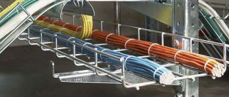
Cables for connecting portable and mobile power receivers in industrial installations
Twisted two-core wires with stranded cores for stationary installation on rollers
Unprotected insulated wires for fixed indoor electrical wiring:
– for conductors connected to screw terminals
– for conductors connected by soldering:
Unprotected insulated wires in external electrical wiring:
Unprotected and protected insulated wires and cables in pipes, metal sleeves and blind boxes
Cables and protected insulated wires for stationary electrical wiring (without pipes, sleeves and blind boxes):
Protected and unprotected wires and cables laid in closed channels or monolithically (in building structures or under plaster)
2.1.15. In steel and other mechanical strong pipes, hoses, boxes, trays and closed channels of building structures, joint laying of wires and cables is allowed (with the exception of mutually redundant ones): 
1. All circuits of one unit. 
2. Power and control circuits of several machines, panels, panels, consoles, etc., connected by the technological process. 
3. Circuits powering a complex lamp. 
4. Circuits of several groups of one type of lighting (working or emergency) with a total number of wires in the pipe no more than eight. 
5. Lighting circuits up to 42 V with circuits above 42 V, provided that the wires of circuits up to 42 V are enclosed in a separate insulating pipe. 
2.1.16. In one pipe, sleeve, box, bundle, closed channel of a building structure or on one tray, the joint installation of mutually redundant circuits, circuits of working and emergency evacuation lighting, as well as circuits up to 42 V with circuits above 42 V is prohibited (for an exception, see 2.1.15 , clause 5 and in 6.1.16, clause 1). The laying of these chains is allowed only in different compartments of boxes and trays that have solid longitudinal partitions with a fire resistance limit of at least 0.25 hours made of fireproof material. 
It is allowed to lay emergency (evacuation) and working lighting circuits on different outer sides of the profile (channel, angle, etc.). 
2.1.17. In cable structures, industrial premises and electrical premises, for electrical wiring, wires and cables with sheaths only made of fire-resistant or non-combustible materials should be used, and unprotected wires - with insulation only made of fire-resistant or non-combustible materials. 
2.1.18. With alternating or rectified current, the laying of phase and neutral (or direct and return) conductors in steel pipes or insulating pipes with a steel sheath must be carried out in one common pipe. 
It is allowed to lay phase and neutral working (or direct and return) conductors in separate steel pipes or in insulating pipes with a steel sheath, if the continuous load current in the conductors does not exceed 25 A. 
2.1.19. When laying wires and cables in pipes, blind boxes, flexible metal sleeves and closed channels, it must be possible to replace wires and cables. 
2.1.20. Structural elements of buildings and structures, closed channels and voids of which are used for laying wires and cables, must be fireproof. 
2.1.21. Connection, branching and termination of wire and cable cores must be carried out using crimping, welding, soldering or clamping (screw, bolt, etc.) in accordance with current instructions approved in the prescribed manner. 
2.1.22. At the points of connection, branching and connection of wire or cable cores, a supply of wire (cable) must be provided, ensuring the possibility of re-connection, branching or connection. 
2.1.23. Connections and branches of wires and cables must be accessible for inspection and repair. 
2.1.24. At junctions and branches, wires and cables should not experience mechanical tension. 
2.1.25. Places of connection and branching of conductors of wires and cables, as well as connecting and branch clamps, etc. must have insulation equivalent to the insulation of conductors of entire sections of these wires and cables. 
2.1.26. Connection and branching of wires and cables, with the exception of wires laid on insulating supports, must be carried out in junction and branch boxes, in insulating housings of connecting and branch clamps, in special niches of building structures, inside the housings of electrical installation products, devices and machines. When laying on insulating supports, the connection or branch of the wires should be made directly at the insulator, the face or on them, as well as on the roller. 
2.1.27. The design of junction and branch boxes and clamps must correspond to the laying methods and environmental conditions. 
2.1.28. Connection and branch boxes and insulating housings of connecting and branch clamps should, as a rule, be made of fireproof or non-combustible materials. 
2.1.29. Metal elements of electrical wiring (structures, boxes, trays, pipes, sleeves, boxes, brackets, etc.) must be protected from corrosion in accordance with environmental conditions. 
2.1.30. Electrical wiring must be made taking into account possible movements at points of intersection with temperature and sedimentary seams. 
Source
Mechanical connection of wires
Threaded connection of wires
Soldering is the most reliable type of connecting wires and contacts. But it has disadvantages - the inseparability of the resulting connections and the high complexity of the work. Therefore, the most common type of connection of wires to electrical contacts of devices is threaded, screws or nuts. To ensure the reliability of this type of connection, it is necessary to perform it correctly.
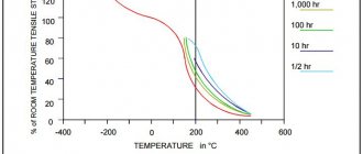
Linear expansion due to temperature changes is different for metals. Aluminum changes its linear dimensions especially strongly, then, in descending order, brass, copper, and iron. Therefore, over time, a gap forms between the contact of the connected metals, increasing the contact resistance. As a result, the screws must be tightened periodically to ensure reliable connections.
In order to forget about maintenance, additional slotted washers, called split washers or Grover washers, are installed under the screws. The Grover selects the gaps that arise and thereby ensures high contact reliability.
Often electricians are lazy and do not twist the end of the wire into a ring. In this option, the contact area of the wire with the contact pad of the electrical device will be many times smaller, which reduces the reliability of the contact.
If the formed ring of wire is slightly flattened with a hammer on an anvil, the contact area will increase several times. This is especially true when forming a ring of stranded wire soldered with solder. Instead of a hammer, you can add flatness with a file, grinding off the ring a little at the points of contact with the contacts.
This is how an ideal threaded connection of wires to contact pads of electrical devices should be made .
Sometimes it is necessary to connect copper and aluminum conductors with each other, or with a diameter of more than 3 mm. In this case, the most accessible is a threaded connection.
The insulation is removed from the wires to a length equal to four screw diameters. If the veins are covered with oxide, then it is removed with sandpaper and rings are formed. A spring washer, a simple washer, a ring of one conductor, a simple washer, a ring of another conductor, a washer and, finally, a nut are put on the screw, screwing the screw into which the entire package is tightened until the spring washer is straightened.
For conductors with a core diameter of up to 2 mm, an M4 screw is sufficient. The connection is ready. If the conductors are made of the same metal or when connecting an aluminum wire to a copper wire whose end is tinned, then there is no need to place a washer between the rings of the conductors. If the copper wire is stranded, then it must first be tinned with solder.
Connecting wires with a terminal block
Connecting wires with low current load can be done using terminal blocks. Structurally, all terminal blocks are designed identically. Thick-walled brass tubes with two threaded holes on the sides of each are inserted into the housing combs made of plastic or carbolite. The wires to be connected are inserted into the opposite ends of the tube and secured.
The tubes come in different diameters and are selected depending on the diameters of the conductors being connected. You can insert as many wires into one tube as its internal diameter allows.
Although the reliability of connecting wires in terminal blocks is lower than when connecting by soldering, much less time is spent on electrical installation. An undeniable advantage of terminal blocks is the ability to connect copper and aluminum wires in electrical wiring, since brass tubes are coated with chromium or nickel.
When choosing a terminal block, you need to take into account the current that will flow through the switched electrical wiring wires and the required number of terminals in the comb. Long combs can be cut into several short ones.
Connecting wires using a Wago flat-spring terminal block
Terminal blocks with flat spring clamps Wago (Wago) from a German manufacturer are widely used. Wago terminal blocks come in two designs. Disposable, when the wire is inserted without the possibility of removal, and with a lever that makes it easy to both insert and remove wires.
The photo shows a Wago disposable terminal block. It is designed for connecting any types of single-core wires, including copper and aluminum with a cross-section from 1.5 to 2.5 mm2. According to the manufacturer, the block is designed to connect electrical wiring in junction and distribution boxes with a current of up to 24 A, but I doubt it. I think it’s not worth loading the Wago terminals with a current of more than 10 A. The proof is given below.
The photo shows a six-pin Wago terminal block, removed during the repair of the kitchen electrical wiring. Despite the small load on the sockets, the only powerful appliances in the kitchen that were connected for a short time were a microwave oven and an electric kettle; the terminal burned out and its body melted. I replaced it with a simple screw terminal block, which has been providing a reliable connection of wires for many years.
Wago spring terminal blocks are very convenient for connecting chandeliers and connecting wires in junction boxes. It is enough just to forcefully insert the wire into the hole of the block, and it will be securely fixed. In order to remove the wire from the block, considerable force will be required. After removing the wires, deformation of the spring contact may occur and a reliable connection of the wires when reconnected is not guaranteed. This is a big disadvantage of a disposable terminal block.
A more convenient Wago terminal block is reusable and has an orange lever. Such terminal blocks allow you to connect and, if necessary, disconnect any electrical wires, single-core, stranded, aluminum in any combination with a cross-section from 0.08 to 4.0 mm2. Rated for current up to 34 A.
It is enough to remove 10 mm of insulation from the wire, lift the orange lever up, insert the wire into the terminal and return the lever to its original position. The wire will be securely fixed in the terminal block.
The Wago terminal block is a modern tool-free way to connect wires quickly and reliably, but is more expensive than traditional connection methods.
About the distribution box
In an apartment or house, wires from the electrical panel are routed to different rooms. There are usually several connection points: switch, sockets, and so on. In order for all the wires to be collected in one place, distribution boxes were created. They carry wiring from sockets, switches and are connected in a hollow housing.
So that during repairs you do not have to look for where the wires are hidden in the walls, electrical wiring is laid on the basis of special rules prescribed in the PUE (Electrical Installation Rules).
The main recommendation is that all connections are made in the junction box.
Distribution boxes are classified according to the type of fastening. So, there are boxes for external installation and internal installation. For the second option, you need to prepare a hole in the wall into which the box will be inserted. As a result, the box lid is located flush with the wall. Often the cover is hidden with wallpaper or plastic during repairs. As a last resort, an outer box is used, which is attached directly to the wall.
There are round or rectangular junction boxes. In any case, there will be at least 4 exits. Each outlet has a fitting or thread to which a corrugated tube is attached. This is done to quickly replace the wire. The old wire is pulled out and new wiring is laid. It is not recommended to lay the cable in a groove on the wall. If the electrical wiring burns out, you will have to dig into the wall and disturb the finish in order to carry out repair work.
How to connect wires correctly?
elalex:
07/24/2014 at 13:16
to Kolka 07/24/2014 at 03:33 1. It’s a matter of taste whether it makes sense to continue the argument, but this is clearly not a dispute between the deaf and the dumb. Let's say I'm trying to find out as much as possible about my installation methods and general contact problems, and at the same time tell about my ideology of approach to PUE. 2.About salt water. Away from emotions, closer to science: do you happen to have data on the electrical conductivity of copper oxides? 3. For me, PUE is not a dogma, but food for thought. If I do not understand the logic of accepting some points and they clearly contradict my common sense, then I do not implement them quite responsibly, and I explain this to the customer. And my guarantee is always more important to my customer than my implementation of the PUE; usually they have absolute trust in me. For example, the famous clauses about the optionality of differential protection of lighting circuits and stationary electric stoves or about dividing the bathroom into zones. I would really like to know the details of the statistics on the use of twists: what type of twists, from what materials, under what operating conditions were destroyed, and what percentage they make up of all such twists. And just in case, to indiscriminately prohibit any twists - I do not accept such an idea as applied to me specifically. 4. According to the suitability of my method of connecting sockets. Of course, it is only suitable for certain types, usually Viko Carmen. It is clear that if someone ever cuts my cable in the socket, then the idea of continuity will not work. I explain to customers to replace the sockets with similar ones and watch the replacement process, although I very much doubt that they will take my advice. I strip the wires with two small kitchen knives. One was taken from the kitchen and was worn to the limit: a 5mm wide tip turned out to be indispensable for removing sheaths (at a level of 5mm from the entrance to the box) and insulating the cores in the depths of junction boxes, especially from broken (up to 1-2cm) old aluminum wires, or cleaning those burnt wires from burnt plastic. This is a renovation for you in a Khrushchev building, not a new installation. I think no other, new, expensive and beautiful one can do this. I don’t pay attention to scratches on the wires when removing insulation from copper; I consider it a trifle. On aluminum, this is a different matter; the insulation is cut only at an oblique angle to the axis of the core, but not perpendicularly, otherwise the wire may actually break off when twisted (but I will definitely notice this). I have not encountered any broken copper wires during twisting due to their cuts; copper is too ductile for this. 5. If possible, there is no need for long analogies with other (non-electric) situations; I am interested in the essence of the objection in a short sentence. 6.I again explained my idea poorly (incompletely). I install 13A machines at 1.5mm2, others use 16A; I set 20A to 2.5mm2, others set 25A, and nothing bad happens to anyone. I am familiar with the protective characteristics of machine guns. What was meant about hot rooms is that a bundle of 3x2.5 VVG cables is laid under the kitchen ceiling. Questions: What kind of automatic devices are used to protect these cables? How much load can they withstand? In what document is all this written? As far as I know from the PUE, and this goes without saying, the amperage of the cores directly depends on the number of cores (in the PUE - in the pipe). The more cores, the stronger the heating, and the less load the cores can withstand. Is this nonsense? I have two calipers, one of which I always have at work, but I use it extremely rarely. The impression is that you are a stern boss. Maybe, in your conditions, punctually fulfilling the PUE is correct, but I need more freedom in decision-making, which is why I left my bosses for free. Maybe in 10 years, when I fall off a stepladder from old age, I will have to become the same. 7.About selectivity. I would be interested to know your opinion about my typical apartment power supply scheme. In the floor panel there is a D63 machine gun. Next is the VVG 5x6 cable (phase and neutral - 2 wires in parallel), in the apartment there are 2 RCDs (not difavtomats), from them groups of circuit breakers B6, B13 (on a 1.5 mm2 line), B20 (on a 2.5 mm2 line), B40 (for an electric stove, line 5x2.5mm2). Any change in this circuit (in terms of protective characteristics, ratings, and the type and location of differential protection) will worsen either the maximum possible power consumption or the selectivity of protection against overloads and short circuits. The problem of the machine D in the floor panel is known to thinking people; there was even an official request from designers to the developers of the Ukrainian PUE. Although unthinking machine gun sellers ask me every time about the style of engines with a long and difficult start. I wonder how it might seem to you that, according to my logic, it is possible to install D machines for group lines? It seems to me that if you can and should put D in one place, this does not mean at all that you can and should put it in another place. 8. As I understand it, I belong to neither the first nor the second type. I have not seen any cases where a laboratory was called in during apartment renovations. But I regularly observe how serious electricians from networks or electrical installation organizations try to transfer their work methods to small jobs such as apartment renovations, but not all of their methods work. You can also live with low-quality electrical equipment for decades and not notice anything bad. As for me, we had a nice conversation.
What are distribution boxes for?
There are many factors that speak in favor of the existence of junction boxes:
- The power system can be repaired in a matter of hours. All connections are accessible, you can easily find the area where the wires have burned out. If the cable was laid in special channels (corrugated tube, for example), then the failed cable can be replaced in an hour;
- Connections can be inspected at any time. As a rule, wiring problems occur at the connection points. If the socket or switch does not work, but there is voltage in the network, first check the quality of the connection in the junction box;
- the highest level of fire safety is created. It is believed that dangerous places are connections. Using a box will keep them in one place.
- minimal time and financial costs when repairing wiring. There is no need to look for broken wires in the walls.
Carrying out work in land and water
The need to install wires in underground or underwater conditions is quite rare. In these cases, certain conditions must be adhered to in order for the contact to be strong and reliable.
Laying wires in water can be done using a special electrical installation - a submersible pump. Then the ends of the conductors are soldered and treated with insulation. You need to put a heat shrink tube on top. If the recommendations and operating conditions are followed, the contact will be of high quality and reliable and will last for many years.
If the electrical wire is laid in the ground, the same method of protection is used. But if you want to make an even more secure connection, you can clamp the ends of the cable with a terminal block.
The connection box for the wires must be sealed. Additionally, it is filled with silicone. To protect against rodents, the wires can be laid in a durable tube or cable.
Connecting the wires in the box
There are several ways in which conductor connections can be made in junction boxes. Note that there are simple and complex methods, however, if executed correctly, all options will ensure the reliability of the electrical wiring.
Method number 1. Twisting method
It is believed that the twisting method is used by amateurs. At the same time, this is one of the most reliable and proven options. PUE do not recommend using twisting, since the contact between the wires is unreliable. As a result, the conductors may overheat, putting the room at risk of fire. However, twisting can be used as a temporary measure, for example, when testing an assembled circuit.
Experts say that even with a temporary connection of wires, all work must be performed according to the rules. It is worth noting that regardless of the number of cores in the conductor, the twisting methods are approximately the same. However, there are some differences. If multi-core wires are connected, then you should adhere to the following rules:
— it is necessary to clean the conductor insulation by 4 cm;
— untwist each conductor by 2 centimeters (along the veins);
— a connection is made to the junction of untwisted cores;
— you only need to twist the wires with your fingers;
— ultimately, the twist is tightened using pliers and pliers;
- exposed electrical wires are covered with insulating tape or heat shrink tubing.
It is much easier to use twisting when connecting solid wires. After the conductors have been stripped of insulation, they must be twisted by hand along their entire length. Then, using pliers (2 pieces), the conductors are clamped: with the first pliers at the end of the insulation, and with the second at the end of the connection. We increase the number of turns on the connection with the second pliers. The connected conductors are insulated.
Method number 2. Mounting caps - PPE
Very often, special caps are used for twisting conductors. As a result, it is possible to obtain a reliable connection with good contact. The outer shell of the cap is plastic (the material is not flammable), and inside there is a metal part with a cone-shaped thread. The insert increases the contact surface, improving the electrical parameters of twisting. Most often, thick conductors are connected using caps (no soldering required).
It is necessary to remove the insulation from the wire by 2 centimeters, slightly twist the wires. When the cap is put on, it must be turned with force. At this point the connection can be considered ready.
Before making the connection, you need to count the number of wires. Based on the data obtained (cross-section), a specific type of cap is selected. The advantages of twisting using plastic caps are that you do not need to spend a lot of time, as with conventional twisting. In addition, the connection is compact.
Method number 3. Connecting conductors by soldering
If you have a soldering iron on your household and you know how to work with it, then the wires can be connected by soldering. Before connecting the wires, they need to be tinned. Soldering flux or rosin is applied to the conductor. Next, the heated tip of the soldering iron is immersed in rosin and passed along the wire several times. A reddish coating should appear.
After the rosin dries, the wires are twisted. Using a soldering iron, tin is taken and the twist is heated until tin flows between the turns. The end result is a high-quality connection with excellent contact. However, electricians are not very fond of using this connection method. The fact is that it takes a lot of time to prepare. However, if you are doing the work for yourself, you should not spare any effort or time.
Method number 4. Welding cores
Using an inverter welding machine, you can connect wires. Welding is used over twisting. You need to set the welding current parameters on the inverter. There are certain standards for different connections:
- conductor with a cross section of 1.5 sq. mm - 30 A;
- conductor with a cross section of 2.5 sq. mm - 50A.
If the conductor is copper, then a graphite electrode is used for welding. The grounding from the welding machine is connected to the upper part of the resulting twist. An electrode is brought from below the twist and an arc is ignited. The electrode is applied to the twist for a couple of seconds. After some time, the connection will cool down, then it can be insulated.
Method No. 5. Terminal blocks
Another option for connecting conductors in a box is using terminal blocks. There are several types of pads: screw, with clamps, but the principle of the device is identical. The most common is a block with a copper plate for attaching wires. By inserting several wires into a special connector, they can be reliably connected. Installation using a clamp terminal makes the connection very simple.
Wire connection methods
There are several methods for connecting electrical wires. You can choose the most convenient and suitable option for your case.
Twist
Twist
Currently, connecting cables in junction boxes using the twisting method is prohibited - it is considered extremely unreliable compared to other existing options. By choosing twisting, you consciously accept all possible responsibility upon yourself.
How to properly splice and branch wires using twisting
The connection itself is extremely simple: approximately 10 mm of insulation is removed from the wires, and then they are carefully screwed onto each other. When connecting wires with a diameter of up to 1 mm, we perform at least 5 turns, in the case of twisting more “serious” cables - from 3 turns.
Crimping
Crimping tool
Popular connection option. It is performed using a special sleeve according to the size of the wire bundle. The sleeve material must also match the cable material.
To crimp the product, press pliers are used to crimp the sleeves. Craftsmen often try to perform crimping using pliers, but professionals recommend refraining from this option, because the connection will not be as reliable.
The work is performed in the following order.
We remove the insulation from the wires, focusing on the length of the sleeve used.
Second step
We twist the wires into a bundle and insert them into the connector.
We crimp the sleeve with the wires using press pliers.
Crimping process
We insulate the finished connection with heat shrink or regular electrical tape.
Crimping process
Welding
Welding
After making such a connection, you get essentially a solid wire, which is not afraid of either oxidation processes or other negative effects characteristic of detachable methods.
To connect wires using the welding method, you need to prepare the following:
- 24V welding machine with power from 1 kW;
- flux;
- carbon electrode;
- protective equipment (gloves, mask/goggles).
We work in this order.
We remove the insulation from the cables and strip the conductors until they shine. To do this we use sandpaper.
Second step
We connect the wires using the twisting method.
We pour flux into the recess of our electrode.
Twist welding machine TS 700 2
We turn on the welding machine, press the electrode against the cables and hold it until a ball forms - the so-called. "contact point".
Fifth step
Welding
We clean the resulting contact point from flux and cover it with varnish.
Finally, all we have to do is insulate the finished connection.
Soldering
Soldering
The procedure remains the same as when connecting wires by welding. The only difference is that the cables are connected using solder melted with a soldering iron. The molten solder should flow into the twist.
It is also not recommended to use soldering in areas of possible mechanical stress on the connection.
Screw terminals
Screw terminals
A great method for quickly and easily connecting wires in a junction box. Compact, inexpensive clamps allow you to connect both homogeneous and dissimilar conductors.
The job is done in two simple steps. You need to do the following:
- strip off approximately 5 mm of insulation from the ends of the wires;
- insert the wires into the clamp and tighten with a screw.
Bolted connections
Bolted connectionsWire termination
The connection is reliable, but very bulky. Suitable for the same bulky old-style boxes. In a modern box, a bolted connection may simply not fit.
The work is performed in the following order.
Second step
We put one of the wires to be connected on top of the bolt. First you need to peel off the insulation and form a ring from the cable. We do the same with the second wire in advance.
Fifth step
We put on the last washer and tighten the connection with a nut.
Of course, a bolted connection also needs insulation, which will not have the best effect on its dimensions.
Methodology for using RCD
Self-clamping connections
The most modern and popular option today. The clamps are extremely easy to use. In addition, such connections initially contain a paste that eliminates the risk of metal oxidation, which allows dissimilar conductors to be inserted into the clips without any fear.
We work in this order.
Self-clamping connections
First step. We remove approximately 10 mm of insulation from each wire.
Second step. Raise the clip lever up.
Third step. Insert the conductors into the connector.
Fourth step. We lower the lever down.
Clamps without levers simply snap into place.
Self-clamping connections
Connecting sockets
Usually a separate line is allocated to the sockets. The box contains three cables of two or three conductors. Each wire is painted a different color. As a rule, brown is the phase, blue is the neutral conductor, and the yellow-green wire is ground. One way or another, in the box all the wires are connected by color, forming groups.
Once the conductors are separated by color, they are folded, stretched, and adjusted to the same length. Don't cut too short - leave a 100mm margin so that you can re-connect if necessary. Having chosen the appropriate connection method, you need to connect the wires.
In old houses there is no grounding, which means there will be only two wires. Sometimes the wires in the cable are the same color. To determine where the phase is and where the zero is, you need to use an indicator screwdriver to determine the phase.
Basic wiring diagrams
When making connections in a junction box, knowing how to connect the wires is not everything. You need to figure out which wires to connect.
How to connect sockets
How to wire a socket from a distribution box? As a rule, the socket group runs on a separate line. In this case, everything is clear: you have three cables in the box, each with three (or two) conductors. In this case, usually brown is the phase wire, blue is neutral (neutral), and yellow-green is ground.
Wiring diagram for a socket in a distribution box
In another standard, the colors may be red, black and blue. In this case, the phase is red, blue is neutral, green is ground. In any case, the wires are collected by color: all of the same color in one group.
How to disconnect a junction box. The wires brought into the junction box are folded, stretched, and cut so that they are the same length. Do not cut short, leave a margin of at least 10 cm so that if necessary you can re-seal the connection. Then the conductors are connected using the chosen method.
If only two wires are used (in old houses there is no grounding), everything is exactly the same, only there are two connections: phase and neutral. By the way, if they are the same color, first find the phase (with a probe or multimeter) and mark it, at least by wrapping a piece of electrical tape around the insulation.
Connecting a single-key switch
If there is a switch, the matter is more complicated. There are also three groups, but their connection is different.
- Eat:
- input - from another junction box or from a panel;
- from the chandelier;
- from the switch.
How should the circuit work? Power - “phase” - goes to the switch key. From its output it is fed to the chandelier. In this case, the chandelier will light only when the switch contacts are closed (the “on” position). This type of connection is shown in the photo below.
Connecting a single-key switch in a distribution box
If you look carefully, this is what happens: the phase with a light wire goes to the switch. It leaves from another contact, but this time blue (do not mix it up) and connects to the phase wire that goes to the chandelier. Neutral (blue) and ground (if network) are twisted directly.
How to connect a switch with one key
If there is a switch in the room, then the connection in the box will be a little more complicated than with only sockets. There will also be three groups of conductors, but the connection is of a different type. Available:
— input cable – from another box or directly from the switchboard;
— wire for the chandelier;
- wire from the switch.
The circuit should work as follows. Power (that is, phase) is supplied to the switch key. From its output a wire is supplied to the lighting fixture. As soon as the switch contacts close, the chandelier will light up. The ground and neutral wires must be twisted together.
Connecting a switch with two keys
Connecting a switch with two keys in a distribution box is more complex than with a single-key switch.
The scheme is characterized by the fact that a cable with three cores must be laid to the device for 2 groups of lamps (if there is no grounding). One conductor is connected to the common contact, and the other two are connected to the output to the keys. You need to remember which conductor (by color) was connected to the common contact. The phase that comes in is connected to the common wire of the switch. The neutral wires from the input, as well as from the two light bulbs, are twisted - three conductors together. There remains a phase wire from the lamps and two from the switch. They are connected in pairs - one conductor from the switch to the phase of one light bulb, and the second output to the remaining lamp.