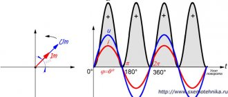
SF6 circuit breakers
Figure 1 – Design of a gas-insulated circuit breaker
An SF6 circuit breaker operates by isolating the phases between each other using gas (usually SF6 electric flow gas is used - the so-called “SF6 gas”). When a signal is received to turn off the equipment, the camera contacts open. They create an electric arc, which is placed in a gas environment. The arc separates the gas into individual components, and the high pressure in the reservoir helps to extinguish it.
Advantages:
- Multifunctional (can be used at any voltage)
- High response speed
- Possibility of use in critical situations (fire, earthquake)
- Long service life
Flaws:
- High cost of construction Inability to work at low temperatures
- Difficulty of maintenance
- The need to install a special foundation for such a structure
Traction and transformer substations - High-voltage AC circuit breakers
Page 13 of 52
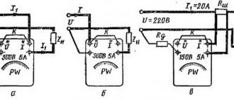
Purpose, classification and main parameters of high-voltage alternating current switches High-voltage switches are the main devices for turning on and off high-voltage circuits (above 1000 V) alternating current in normal and emergency (short-circuit) modes. Based on the type of arc-extinguishing medium, switches are divided into oil, air, gas-generating, vacuum and SF6. Switches are also distinguished according to the following characteristics: by the number of phases - one, two and three-phase; installation location - for indoor and outdoor; control method - with manual or remote drive; shutdown time - high-speed (up to 0.08 s), accelerated (up to 0.12 s), slow-acting (up to 0.25 s). Operation of high-voltage switches of normal design is provided at ambient temperatures from + 35 to -40 ° C at an altitude of no more than 1000 m above sea level. In addition to the normal design, high-voltage switches of special designs are produced for operation in northern, tropical, high-mountain, chemically active environments, etc. Switches must meet the following requirements: reliably disconnect circuits under factory-guaranteed conditions; ensure convenience and safety of operation; allow automatic reclosure (AR) after a trip. All parameters of the switch are indicated in the attached passport, and the main ones are indicated on its panel; they characterize the conditions for reliable operation of the circuit breaker. The most important parameters of the switch are the following. Rated voltage Unom (linear), which determines the quality and dimensions of the insulating parts, and therefore all dimensions of the switch and its weight. The switch can be used in installations with an operating voltage below the rated voltage, as this will not damage its insulation. Manufacturers also guarantee the operation of switches at elevated voltages, which should not exceed the rated voltage by 20% for switches with voltages up to 35 kV and by 15% for switches with voltages of 110 and 220 kV. Below are the relationships between the nominal Un and the largest working Hnaib. slave voltage in kV: 6/7.2; 10/12; 35/40.5; 110/126; 220/252. Rated current is the highest current (rms value) that the switch is capable of carrying for a long time at rated voltage, rated frequency and rated ambient temperature, while the temperature of the switch parts should not exceed that permissible for long-term operation. Thus, the rated current characterizes the long-term operation of the circuit breaker without overheating of live parts and contacts; it determines their dimensions, but does not affect the dimensions of the circuit breaker. The rated breaking current is the highest short-circuit current (the effective value of the periodic component of the short-circuit current) that is capable of reliably opening the circuit breaker at a voltage equal to the highest operating voltage in a certain operating cycle when the voltage in the corresponding electrical circuit is restored. There are two operating cycles for AC circuit breakers: with and without automatic reclosure. The cycle with automatic reclosure has the form OT-BO-180-BO, where O is the switch off by relay protection in the event of a short circuit on the protected circuit; T is the minimum current-free pause guaranteed for the circuit breaker for deionization of the medium before reclosing; VO - turning on the circuit breaker by an automatic reclosure device and immediately turning it off by relay protection; 180—time period, s, until the next switch on; VO - enable and disable. In a cycle without automatic reclosure, after the relay protection switch is turned off during a short circuit in the circuit, it can be turned on for this short circuit 2 more times, but with an interval of at least 180 s. This cycle is designated O-180-VO-180-VO. Most modern circuit breakers satisfy the autoreclose cycle, especially high-speed ones, in which the process of deionization of the arc gap and the medium is carried out actively. The need for fast shutdown and complete deionization of the environment is due to the fact that automatic reclosure ensures stable operation of the electrical system only if it occurs no more than 0.5 s after the circuit breaker is turned off. The rated disconnecting power is the highest power that the switch can reliably disconnect in short-circuit mode without mechanical damage or melting of the contacts. Dynamic withstand current is the largest value of the amplitude of the total short-circuit current that the switch can withstand in the on position without damage preventing its further operation. Thermal resistance current is a current such that, when flowing during time t,r, the temperature of the current-carrying parts of the switch should not exceed the permissible value for short-term operating mode. The tripping time of a motorized circuit breaker represents the time interval from the issuing of the tripping command until the arc goes out on all poles. It is equal to the sum of the intrinsic shutdown time of the circuit breaker with the tc.v drive. and arc burning time, i.e. toff. The proper shutdown time represents the time interval from the moment a current pulse is applied to the tripping coil of the circuit breaker drive until the moment the arcing contacts diverge. The arc burning time is the time interval from the beginning of the divergence of the arc extinguishing contacts until the moment the arc goes out at all poles. Technical solutions in the field of production of high-voltage switches are aimed at increasing parameters and reducing the dimensions of switches through the use of higher quality insulating materials and effective methods of arc extinguishing.
- Back
- Forward
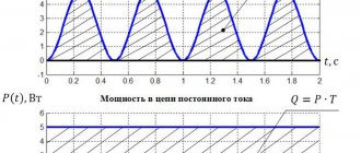
Vacuum circuit breakers
Figure 2 – Design of a vacuum circuit breaker
The operating principle of a vacuum switch is based on the high dielectric strength of vacuum and its dielectric properties. At the moment the contacts open, an arc occurs in the gap between them due to the evaporation of metal from their surface. When the current passes through zero, the vacuum restores the dielectric properties and the arc no longer occurs.
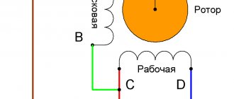
Figure 3 – Operating principle of a vacuum circuit breaker
Advantages:
- Ease of design and repair
- Ability to work not only in a horizontal position
- Reliability and long service life
- Compactness
- Low fire hazard
Flaws:
- Small resource during short circuit
- Risk of switching overvoltages
- High price
Classification of high-voltage circuit breakers
By arc extinguishing method
§ SF6 circuit breakers (tank and column);
§ Vacuum circuit breakers;
§ Oil switches (tank and low oil);
§ Air circuit breakers.
By purpose
§ Network switches for voltages from 6 kV and higher, used in electrical circuits (except for circuits of electrical machines and electrothermal installations) and intended for passing and switching current under normal operating conditions of the circuit, as well as for passing for a given time and switching current in given abnormal conditions such as short circuit conditions
§ Generator circuit breakers for voltages from 6 to 20 kV, used in circuits of electrical machines (generators, synchronous compensators, powerful electric motors) and designed for passing and switching current under normal conditions, as well as in starting modes and during short circuits.
§ Switches for voltages from 6 to 220 kV for electrothermal installations , used in circuits of large electrothermal installations (for example, steel-smelting, ore-smelting and other furnaces) and designed for passing and switching current under normal conditions, as well as in various operating modes and during short circuits .
§ Special purpose switches.
By type of installation
§ Supported , that is, having basic insulation to the ground of a support type.
§ Suspended , that is, having the main insulation to the ground of a suspended type.
§ Wall-mounted , that is, mounted on the walls of closed switchgears.
§ Roll-out , that is, having devices for rolling out from switchgear cells.
§ Built into complete distribution devices.
By accommodation category and climatic version
§ five categories of placement (outdoor and indoor with different heating and ventilation conditions);
§ six climatic versions (U, HL, TV, TS, T and O) depending on the geographical location of installation.
General structure and principle of operation of air switches
In air circuit breakers (AC), the energy of compressed air is used both as a driving force that moves contacts and as an arc extinguishing medium. The principle of operation of the arc extinguishing device (AD) is that the arc formed between the contacts is subjected to intensive cooling by a stream of compressed air flowing into the atmosphere. When the current passes through zero, the arc temperature drops and the gap resistance increases. At the same time, mechanical destruction of the arc column and removal of charged particles from the gap occurs.
Explosives are structurally divided into:
§ Switch with open separator
§ Switch with gas-filled separator
§ Switch with chambers in a compressed air tank
General structure and principle of operation of SF6 circuit breakers
The insulating and extinguishing medium of the switches is sulfur hexofluoride SF6 (SF6 gas). The switches are a three-pole device, the poles of which have one (common) frame and are controlled by one drive, or each of the three poles of the switches has its own frame and is controlled by its own drive (pole-controlled switch).
The operating principle of the devices is based on extinguishing the electric arc (occurring between divergent contacts when the current is turned off) by a flow of SF6 gas.
There are two sources of gas flow:
§ an increase in pressure in one of the gas-filled cavities of the arc extinguishing device, due to a decrease in its closed volume, the possibility of gas flow from which into the divergence zone of the arc extinguishing contacts appears immediately before their opening
§ an increase in gas pressure in the same cavity due to its expansion under the influence of the thermal energy of the electric arc itself.
The first source prevails when switching off small currents, and the second – when switching off large ones.
Switch pole
For the column design, the pole is a vertical column consisting of two (or more) insulators, the top of which houses an arc extinguishing device (AD), and the lower one serves as a support for the DU and provides it with the required insulating distance from the grounded frame. Inside the support insulator there is an insulating rod connecting the moving contact of the remote control with the drive system of the device.
For the tank version, the pole is a metal cylindrical tank on which two insulators are installed, forming the high-voltage inputs of the circuit breaker. The remote control in such a switch is located in a grounded metal case.
For the combined design, the pole is a metal case in the form of a sphere, on which porcelain insulators are installed, forming the high-voltage inputs of the switch, one of which houses an arc extinguishing device, and the other has built-in current transformers.
A filter is usually installed in the upper part of the insulator - an absorber of moisture and decomposition products of SF6 gas under the action of an electric arc. The filter element in it is an activated adsorbent – synthetic zeolite NAX.
Also, all modern switches are equipped with a safety valve - a device with a thin-walled membrane that bursts at the pressure that occurs during an internal short circuit, but does not reach the value at which the insulators themselves are tested.
Arcing device
The arc extinguishing device is designed to quickly extinguish the electric arc that forms between the switch contacts when they open. The development of a rational and reliable design of an arc extinguishing device presents significant difficulties, since the processes that occur when extinguishing an electric arc are extremely complex, have not been sufficiently studied and are determined by many factors, which are not always possible to foresee in advance. Therefore, the final development of an arc extinguishing device can be considered complete only after its experimental verification.
Modern circuit breakers are equipped with an auto-compression type arc extinguishing device, which demonstrates its design advantages when switching off high currents.
The remote control contains fixed and movable contact systems, each of which has main contacts and arc-extinguishing contacts equipped with elements made of arc-resistant material. The main contact of the fixed system and the movable arc extinguishing are of the socket type, and the main contact of the movable system and the fixed arc extinguishing are of the pin type.
The movable system contains, in addition to the main and arc-extinguishing contacts, a stationary current-carrying sleeve connected to the current output of the remote control; a piston device that creates increased pressure in the sub-piston cavity when switched off, and two fluoroplastic nozzles (large and small), which direct gas flows from the high pressure zone to the divergence zone of the arc extinguishing contacts. The large nozzle, in addition, prevents the radial displacement of the contacts of the moving system relative to the contacts of the fixed one, since it never leaves the guide sleeve of the main fixed contact.
The main contact of the moving system is a stepped copper sleeve, the narrow part of which is adapted to the entrance to the socket main contact of the fixed system, and the wide part has two streams in which current-collecting (closed wire) spirals are placed, constantly in contact with the fixed current-carrying sleeve enclosing them .
Gas system
The gas system of the devices includes:
§ autonomous sealing valves (ASVs) and column filling valves;
§ a manifold, which ensures the connection of the gas cavities of the columns with each other and with a signaling device for changes in SF6 gas density during operation of the apparatus;
§ the signaling device itself, which is a pointer electric contact pressure gauge with a temperature compensation device that brings the readings to the pressure value at a temperature of 20ºC;
§ connecting tubes with nipples and seals.
The indicator for changes in SF6 gas density (density sensor) has three pairs of contacts, one of which, which closes when the density of SF6 gas decreases significantly due to its leakage, is intended to provide a signal (for example, light) about the need to refuel the columns; and the other two, which open when the SF6 gas density drops unacceptable, are designed to block switch control or to automatically turn off the device while simultaneously blocking switching on (which is determined by the substation design).
Drive unit
Switch drives provide control of the switch - turning on, holding in the on position and turning off. The drive shaft is connected to the switch shaft by a system of levers and rods. The switch drive must provide the necessary reliability and speed of operation, and with electrical control, the lowest power consumption.
Two types of drives are used in SF6 circuit breakers:
Spring drive:
§ The energy accumulator is a set of helical coil springs
§ The control body is a kinematic system of levers, cams and shafts.
Spring-hydraulic drive:
§ The energy accumulator is a set of disc springs
§ The control body is the hydraulic system.
Requirements for switches
The switch is the most important device in a high-voltage system; in case of emergency, it must always ensure smooth operation. If the switch fails, an accident develops, which leads to severe destruction and large material losses associated with undersupply of electricity and the cessation of work of large enterprises.
In this regard, the main requirement for switches is particularly high reliability of their operation in all possible operating modes. Disabling any loads by the switch should not be accompanied by overvoltages that are dangerous for the insulation of the installation elements. Due to the fact that the short circuit mode is the most severe for the system, the switch must ensure that the circuit is disconnected in the shortest possible time.
General requirements for the designs and characteristics of switches are established by the following standards:
§ GOST R52565-2006 “AC switches for voltage from 3 to 750 kV. General technical conditions."
§ GOST 12450-82 “High voltage alternating current switches. Disabling unloaded lines."
§ GOST 8024-84 “Permissible heating temperatures of current-carrying elements, contact connections and contacts of apparatus and electrical devices of alternating current for voltages over 1000 V.”
§ GOST 1516.3-96 “Alternating current electrical equipment for voltages from 1 to 750 kV. Requirements for electrical insulation strength."
Removing the circuit breaker for inspection and repair is associated with great difficulties, since you have to either switch to another switchgear scheme or simply disconnect consumers. In this regard, the switch must allow as many short circuit trips as possible without inspection and repair. Modern circuit breakers can disconnect up to 15 short circuits without inspection at full tripping power.
21. Current-limiting reactor is an electrical device designed to limit short-circuit current. It is connected in series to the circuit and works as an additional inductive resistance that reduces the current during a short circuit, which increases the stability of the generators and the system as a whole.
Application
During a short circuit, the current in the circuit increases significantly compared to the normal mode current. In high-voltage networks, short circuit currents can reach such [ what?
] values that it is not possible to select installations that could withstand the electrodynamic forces arising from the flow of these currents. To limit the short circuit current, current-limiting reactors are used.
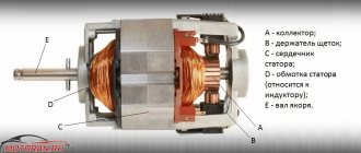
Oil switches
Figure 4 – Design of the oil switch
In arc extinguishing devices of oil switches, the arc is extinguished by means of its effective cooling in the flow of gas and steam generated during the decomposition and evaporation of the oil
Advantages:
- Reliability
- Simplicity of design and operation
- Strength
Flaws:
- Large dimensions
- Fire hazard
- Difficult to install
Air circuit breakers
Figure 5 – Air circuit breaker design
The principle of operation of the air circuit breaker is to extinguish the arc using a high-speed flow of compressed air directed into the blow channels. Under the influence of the air flow, the arc is stretched and directed into the blow channels, where it is finally extinguished.
Advantages:
- High response speed
- High fire safety
- Long service life
Flaws:
- High cost of equipment and installation (compressors, receivers, etc.)
- The need for regular maintenance
Air switches
To extinguish the arc, air-type switches use compressed air under a pressure of 2-4 MPa. The arc extinguishing device and live parts are insulated using porcelain and other similar materials. Air circuit breakers differ in design depending on factors such as rated voltage, method of compressed air supply, and others.
High rated current devices, similar to low-oil circuit breakers, are equipped with a main and arc extinguishing circuit. When turned on, the main current flows to the main contacts, which are located openly. After switching off, they open first and then the current flows to the arc extinguishing contacts located in another chamber. Immediately before they open, compressed air is supplied from the reservoir to the chamber, extinguishing the arc, in the longitudinal or transverse direction.
In the disconnected position, an insulating gap of the required dimensions is created between the contacts. For this purpose, the contacts are separated at a sufficient distance. Switches for indoor installation are designed for currents up to 20 thousand amperes and voltages of 10-15 kV. They have an open type separator, after which the compressed air stops flowing into the chambers and the arc extinguishing contacts close.
A typical air circuit breaker design consists of an arc chute, a compressed air reservoir, main contacts, a shunt resistor, an isolator and a 110 kV capacitive voltage divider providing two breaks per phase. In open circuit breakers designed for a voltage of 35 kV, one break per phase is sufficient.
Load switches
A load switch is a high-voltage switching device that occupies an intermediate position between a disconnector and a circuit breaker in terms of the permissible load of switching currents. Capable of disconnecting without damage both rated load currents and overcurrents in emergency modes. The load switch allows switching the rated current, but is not designed to interrupt short-circuit currents.
According to the principle of arc extinguishing, load switches are classified:
- Autogas (the most common type)
- Vacuum
- SF6
- Air
- Electromagnetic
In distribution networks, the most common designs of load switches (VNR, VNA, VNB) with gas-generating type extinguishing devices.
Figure 6 – Load switch with gas-generating type extinguishing devices (BH) a – general view of the switch; b – extinguishing chamber
As can be seen from the figure, the device is based on the elements of a three-pole disconnector for indoor installation. Extinguishing chambers are mounted on the support insulators of the disconnector. But the disconnector drive is modified to ensure sufficient response speed when turning on and off.
In the “on” position, the knives enter the extinguishing chambers. The disconnector contacts and the sliding contacts of the extinguishing chambers are closed. When the current is turned off, the contacts of the disconnector are first turned off, then the current is shifted through the auxiliary knives into the extinguishing chambers. After this, the contacts in the chamber open. Arcs are ignited and extinguished in a flow of gases, which are products of decomposition of the plexiglass liners located in the chamber. In the "off" position, the auxiliary knives are located outside the extinguishing chambers, providing sufficient insulation breaks.
High voltage switches. Classification and main parameters.
BBs are used to turn on and off a high-voltage circuit. In normal, not normal and emergency modes.
The following requirements apply to explosives:
1 operational reliability
2 minimum circuit shutdown time
3 small dimensions and weight
4 convenience, safety of installation and operation
5 possibility of using automatic restart.
The reliability of the switch determines the reliability of the electrical installation and even the entire power supply system.
The minimum shutdown time (speed) reduces the thermal effect of the short-circuit current, as well as the risk of the accident spreading to other installations.
According to the principle of arc extinguishing and the type of arc extinguishing medium, switches are divided into: oil, air, electromagnetic, SF6, vacuum.
Currently, most oil switches are used, but they are already being replaced by vacuum or SF6 switches. Airborne and electromagnetic ones have not become widespread on railways. In oil switches, arc extinguishing occurs in the oil.
Oil switches
are divided into:
1
multi-volume (in which oil is used as an arc extinguishing medium and as insulation)
2
low-volume (oil is used only for arc extinguishing)
Air circuit breakers –
The arc is extinguished using a jet of compressed air.
Electromagnetic switches
extinguishing occurs in the air, but the arc moves in an electromagnetic field.
In SF6
In switches, arc extinction occurs in an environment of sulfur hexafluoride.
In vacuum
Switches are extinguished in a vacuum.
High voltage circuit breakers are classified:
By number of phases (1.3)
By installation location (indoor or outdoor)
By speed (up to 0.08 fast-acting, up to 0.12 accelerated, up to 0.25 not fast-acting)
Main parameters of explosives:
1-Un
rated voltage (is this linear voltage? which determines the quality and dimensions of the insulating parts of the switch and their dimensions)
2-In
rated current (characterizes the long-term operation of the circuit breaker without overheating of live parts and contacts and determines their dimensions, but not explosives)
3-In.off
. rated breaking current (this is the highest current that reliably trips the circuit breaker at Un and a given operating cycle)
4-
This is the rated shutdown power - the power that the switch reliably turns off in short-circuit mode without mechanical damage and contact melting.
5-iud.max iprs.sk
– this is the largest value of the amplitude of the total short-circuit current. Which the switch maintains in the on position without damage and preventing its further operation.
6-it-
The maximum thermal resistance current is the largest root mean square value of the short-circuit current flowing through the switch for a certain period of time t during which the heating temperature of the current-carrying parts will not cause damage, preventing. long-range operation of the switch.
7-tv
– circuit breaker shutdown time, tв=tсв+tд is the period of time from the issuing of the shutdown command until the moment the arc goes out.
8- tsv
the switch's own response time is the time interval from the issuing of the shutdown command to the start of contact separation.