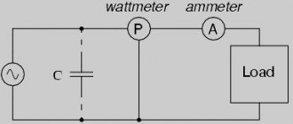
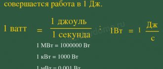
AC power
Within an alternating current circuit, there are three types of power: active type or P, reactive type or Q, and full type or S. In the first case, the standard unit of measurement is the Watt (W or W), and the formula for calculating active power parameters is:
P = U × I × cos φ.
The calculations of positive or negative active power directly depend on the characteristics of the phase shift angle coefficient or the latter indicator.
For reactive type power measurements, a special volt-ampere with the designation “Var” or Var is used.
This value characterizes the loads that are formed inside electrical structures under the influence of oscillations of electromagnetic fields in alternating sinusoidal current circuits.
The calculation is carried out on the basis of root-mean-square voltage and current parameters multiplied by the angular sinusoid of the phase shift, according to the values:
Q = U × I × sin φ.
In conditions of values at the level of 0/+90°, the sine value will be positive, and for values within the range of 0/-90° - only negative. Measurements of total electrical power are carried out exclusively in volt-amperes (VA or V A).
Dependence of power on time for alternating and direct current
The value corresponding to the product of the standard voltage in the clamping area with the indicators of periodic electric current inside the circuit should be calculated in accordance with the formulas:
S = U × I or S = √Р2 + Q2, where
- the P value is represented by active power;
- Q2 value is an indicator of reactive power.
Of no small importance is the complex power corresponding to the impedance. In any case, it must be taken into account that positive power corresponds to P > 0, and negative power corresponds to P < 0.
Large domestic producers of electrical energy generate alternating current with a so-called industrial frequency of 50 Hz and voltage levels in the range of 10-20 kV, and the electrical voltage is increased at special transformer substations.
Total power and its components
Electrical power (P) in physics is a measure that shows how quickly the transformation or transfer of electricity occurs. The unit of measurement is watt (W, W). The value of P depends on the voltage (U) and current (I) in the closed circuit.
For direct current, the load consumed by P is the result of the product of current and voltage:
P = I*U (A*B = W).
P in a constant current circuit
Attention! In this case, the values of both electrical characteristics are constant, which means that at every second of time their values are instantaneous.
The formula changes form if there is a source of electromotive force E (EMF) in the circuit:
P = I*E.
For circuits where the current changes its values periodically along a sinusoid, this formula is not suitable. It is necessary to calculate P based on its instantaneous values in the time interval.
The total power S in its value corresponds to the expression:
S = U*I,
Where:
- U – potential difference at the terminals, (V);
- I – current, (A).
To designate S, use the non-systemic unit B*A (V*A).
Loads included in variable current circuits can be:
- active;
- reactive: capacitive or inductive.
Active load (AH)
A similar load is the elements of devices that have active resistance. The working part of such devices heats up when electricity passes through them.
The current passing through the load does work, which is spent on heating and releasing thermal energy. How is this load measured? It is measured in ohms (ohms).
Examples of AN include: iron, electric stove, hair dryer coils, lamp filament, resistive resistance.
For your information. AN behaves the same way both with constant and with time-varying current.
Example AN
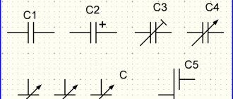
Capacitive load
Devices that can store energy in an electric field and create recirculation (full or partial return) of power are called capacitive loads. A capacitive load (EC) at an alternating voltage, passing current, shifts its phase forward by 900.
The main elements related to EN are:
- capacitors;
- cable lines (capacitance between cores);
- Power lines (power lines) of ultra-high voltage;
- generators operating in overexcitation mode.
EH delivers reactive power (Q).
Circuit with capacitor
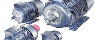
Inductive load (IN)
A load in which the current is phase-shifted back from the voltage by 900 is called inductive. She also consumes Q.
Chain with coil
When an inductor (choke), which has a low active resistance, is connected to an alternating voltage network, an emf is formed in it. Electromotive force opposes applied voltage.
Important! In the case of pure inductance L, the resistance to sinusoidal current increases with increasing frequency. The average power P released by such a load is zero.
Examples of ID are:
- asynchronous motors;
- electromagnets;
- chokes;
- reactors;
- transformers;
- rectifiers
This also includes thyristor converters.
AC Power Formula
The power indicators of an alternating type electric current are the product of the current data and the voltage, and the level will be zero in conditions of passing through zero, but necessarily maximum at the peak amplitude.
Despite the complexity of measuring power, it is important to remember that such data are not representative, so from a practical point of view, the active average power in a certain period is of interest.
In a single-phase circuit
For a single-phase circuit, the formula for determining the total power is used: S = U × I , where
- S —indicators of total power characteristics (Ba);
- I is the level of effective electric current taking into account the generator winding (A);
- U - parameters of the calculated effective voltage value in the generator (V).
The full power characteristics taken into account in standard independent calculations affect the dimensions of the generator with variable electric current, which is determined by the cross-section and number of turns of the winding wires, as well as the thickness of the insulating material. For active and reactive resistance, the power consumed in active resistance and in the reactive part is important.
Single-phase AC electrical circuits
Reactive power indicators are caused by energy fluctuations under conditions of the formation and loss of electric or magnetic fields. The electrical energy stored within the field of such resistance is progressively returned back to the generator, which is connected to a standard electrical circuit.
The presence of reactive currents between the reactive receiver and the generator, which have inductive and capacitive reactance, contributes to the useless load of the line and generator, which is accompanied by additional energy losses.
Types of capacities
Power is a measured physical quantity that is equal to the rate of change with the conversion, transmission or consumption of system energy. According to a narrower concept, this is an indicator that is equal to the ratio of time spent on work to the period itself spent on work. In mechanics it is designated by the symbol N. In electrical engineering the letter P is used. You can often also see the symbol W, from the word watt.
AC power is the product of current, voltage and cosine of the phase shift. In this case, only the active and reactive varieties can be easily counted. You can find out the full power value through the vector dependence of these indicators and area.
Main power varieties
Active power
Active is called useful force, which determines the process of direct conversion of electricity into the required type of force. In each electrical appliance it is transformed in its own way. For example, a light bulb produces light with heat, an iron produces heat, and an electric motor produces mechanical energy. Accordingly, it shows the efficiency of the device.
Active variety
Reactive power
Reactive is the one that is determined using an electromagnetic field. Formed during the operation of electrical appliances. Note! This is a harmful and parasitic power characteristic, which is determined by the nature of the load. For a light bulb it is zero, but for an electric motor it can be a large value.
The difference between the values is that the active power characteristic shows the efficiency of the devices, and the reactive one is the transfer of this efficiency. The difference is also observed in definition, symbol, formula and significance.
Note! As for the meaning, the second is needed only to control the voltage created from the first value and overcome power fluctuations. Both are measured in watts and have a large meaning in electromagnetic radiation, the mechanical form of a generator or an acoustic wave. Actively used in industry.
Jet variety
Full power
Total is the sum of active and reactive power. Equal to the network power indicator. This is the product of voltage and current while ignoring the phase of the angle between them. All energy dissipated with absorbed and returned is total energy.
It is the product of voltage and current, the unit of which is watt multiplied by ampere. When the circuit is active, the total is equal to the active. If we are talking about an inductive or capacitive circuit, then the total is greater than the active.
You might be interested in which electric current is more dangerous for humans and why
Full variety
Complex power
This is the sum of all power indicators of the phases of the electricity source. This is a complex indicator, the module of which is equal to the full power indicator of the electrical circuit. The argument is the phase shift between the electric current and the mains voltage. It can be expressed by an equation where the total power indicator that is generated by electricity sources is equal to the total power indicator that is consumed in the electrical circuit.
Note! Calculated by using the appropriate formula. So, it is necessary to multiply the complex voltage by the complex current or multiply the double value of the complex current by the impedance. You can also divide twice the complex voltage by twice the impedance.
Complex variety
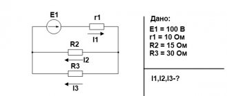
In a three-phase circuit
The power indicators of alternating current with a uniform three-phase load are determined by the presence of an equivalent current flowing through the conductors of the phase. In this case, the current indicators under the conditions of using the neutral conductor are “O”. Formula for calculating alternating current power under three-phase network conditions: P = 3 × U φ × I × cos(φ).
Symmetrical (uniform) phase load in a three-wire three-phase current circuit
The flow of currents of different magnitudes inside phase conductors represents an asymmetrical or uneven load. In this case, it is the asymmetrical load that is accompanied by the flow of current through the zero or neutral wires, therefore the level of power indicators is determined in accordance with the standard and well-known formula:
Total = Ua × Ia × cos(φ1) + Ub × Ib × cos(φ2) + Uс × Iс × cos(φ3).
Average power in active load
The power parameters of the electrical network or any installation are the most important data of almost any electrical device. The transmission of passing or consumed power characteristics of the active type is carried out over a certain period of time.
Table values of average power characteristics of main household appliances
| Device | Indicators |
| Charger | 2.0 W/hour |
| Fluorescent lamps "DRL" | 50 W/hour or more |
| Electric kettle | 1.5 kW/hour |
| Acustic systems | 30 W/hour |
| Washing machine | 2.5 kW/hour |
| High pressure washing | 3.5 kW/hour |
| Semi-automatic inverters | 3.5 kW/hour |
| Kitchen blender | 1.0-1.2 kW/hour |
| Microwave oven | 1.8 kW/hour |
| Kitchen toasters | 1.2 kW/hour |
| TV | 0.2 kW |
| Fridge | 0.4 kW |
| Vacuum cleaner | 1.0 kW |
| Desktop computer | 0.55 kW |
| Electric stove | 2.5 kW/hour |
| Hair dryer | 1.0 kW/hour |
| Iron | 1.0 kW/hour |
| Electric oven | 1.2 kW/hour |
| Electric heater | 1.4 kW/hour |
Definition
Only alternating current can have active and reactive power, since the network characteristics (current and voltage) of direct current are always equal. The unit of measurement for active power is Watt, while reactive power is measured by reactive voltampere and kiloVAR (kVAR). It is worth noting that both full and active characteristics can be measured in kW and kVA, this depends on the parameters of the specific device and network. In industrial circuits it is most often measured in kilowatts.
Energy ratio
Electrical engineering uses the active component to measure the energy transfer of individual electrical devices. Let's look at how much power some of them consume:
| Device | Power of household appliances, W/hour |
| Charger | 2 |
| Fluorescent lamp DRL | From 50 |
| Acoustic system | 30 |
| Electric kettle | 1500 |
| Washing machine | 2500 |
| Semi-automatic inverter | 3500 |
| High pressure washer | 3500 |
Based on everything said above, active power is a positive characteristic of a specific electrical circuit, which is one of the main parameters for selecting electrical appliances and controlling electricity consumption.
Active component generation
Reactive component designation:
This is a nominal value that characterizes the loads in electrical devices using EMF fluctuations and losses during operation of the device. In other words, the transmitted energy goes to a specific reactive converter (this is a capacitor, diode bridge, etc.) and is manifested only if the system includes this component.
Power in the presence of a phase shift between current and voltage
Under conditions of alternating electric current, coincidences in current direction and voltage are noted only in the absence of coil induction and capacitors. In this case, the vector directions of current and voltage are identical. The presence of coils and a capacitor in the circuit is accompanied by the coincidence of current phases and voltage indicators, but vector rotation occurs at the same speed and at constant angle parameters.
The phase shift or shift coincides with the angle that is observed between the vector radii of the current indicators and voltage parameters, and a lag in these criteria provokes a mismatch.
AC current and voltage phase shift
In this case, the power characteristics are negative due to the product of positive and negative quantities. In such conditions, an external type electrical circuit becomes the standard source of electricity. A small amount of energy entering the circuit at positive power values is returned only in the presence of negative values.
The duration of parts of the period directly depends on the level of phase shift, while the displacement indicators are determined by the duration of negative powers, or the so-called average power characteristics of the electric current.
Characteristics
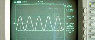
Alternating current flows through a circuit and changes its direction with magnitude. Creates a magnetic field. Therefore, it is often called periodic sinusoidal alternating electric current. According to the law of a curved line, its value changes after a specific period of time. That's why it's called sinusoidal. Has its own parameters. The important ones are to indicate the period with frequency, amplitude and instantaneous value.
A period is the time during which the electric current changes, and then it repeats again. Frequency is the period per second. Measured in hertz, kilohertz and millihertz.
Amplitude is the maximum current value with voltage and flow efficiency over a full period. Instantaneous value is an alternating current or voltage that occurs during a specific time.
You may be interested in Determining voltage drop
AC Characteristics
Power balance
Independently finding some electrical unknowns, as a rule, requires mandatory verification of the correctness of the obtained values, taking into account the power balance.
In accordance with generally accepted characteristics, the balance in an electrical circuit is based on the law of conservation of energy, therefore the total power consumed and supplied must be equal.
The calculations take into account equivalent resistance indicators and Ohm’s law, familiar to most from physics courses.
Small discrepancies in values are allowed, which is caused by standard roundings carried out in the process of performing independent calculations. Thus, regardless of the level of complexity of the created circuit, the balance must converge, which is a guarantee of maintaining operability and complete operational safety.