PWM operating principle
The pulse width modulated signal is generated in two ways:
- analog;
- digital.
With the analog method of creating a PWM signal, the carrier in the form of a sawtooth or triangular signal is supplied to the inverting input of the comparator, and the information input is supplied to the non-inverting input. If the instantaneous carrier level is higher than the modulating signal, then the output of the comparator is zero, if lower – one. The output produces a discrete signal with a frequency corresponding to the frequency of the carrier triangle or saw, and a pulse length proportional to the level of the modulating voltage.
As an example, the pulse width modulation of a linearly increasing triangular signal is given. The duration of the output pulses is proportional to the output signal level.
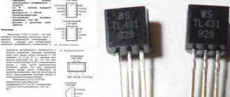
Analog PWM controllers are also available in the form of ready-made microcircuits, inside of which a comparator and a carrier generation circuit are installed. There are inputs for connecting external frequency-setting elements and supplying an information signal. The signal that controls powerful foreign keys is removed from the output. There are also inputs for feedback - they are needed to maintain the established control parameters. This is, for example, the TL494 chip. For cases where the consumer power is relatively small, PWM controllers with built-in switches are produced. The internal key of the LM2596 chip is designed for current up to 3 amperes.
The digital method is carried out using specialized chips or microprocessors. The pulse length is regulated by an internal program. Many microcontrollers, including the popular PIC and AVR, have a built-in module on board for hardware implementation of PWM; to receive a PWM signal, you need to activate the module and set its operating parameters. If such a module is missing, then PWM can be organized using a purely software method, it is not difficult. This method provides greater capabilities and greater freedom due to flexible use of outputs, but uses more controller resources.
Application area
With the development of microcontroller technology, new opportunities have opened up for PWM. This principle has become the basis for electronic devices that require both adjusting output parameters and maintaining them at a given level. The pulse-width modulation method is used to change the brightness of light, the rotation speed of motors, as well as in controlling the power transistor of pulse-type power supplies (PSUs).
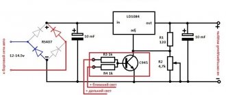
Pulse width (PW) modulation is actively used in the construction of LED brightness control systems. Due to low inertia, the LED has time to switch (flash and go out) at a frequency of several tens of kHz. Its operation in pulse mode is perceived by the human eye as a constant glow. In turn, the brightness depends on the duration of the pulse (open state of the LED) during one period. If the pulse time is equal to the pause time, that is, the duty cycle is 50%, then the brightness of the LED will be half of the nominal value. With the popularization of 220V LED lamps, the question arose of increasing the reliability of their operation with unstable input voltage. The solution was found in the form of a universal microcircuit - a power driver operating on the principle of pulse width or pulse frequency modulation. A circuit based on one of these drivers is described in detail here.
The mains voltage supplied to the input of the driver chip is constantly compared with the in-circuit reference voltage, generating a PWM (PWM) signal at the output, the parameters of which are set by external resistors. Some microcircuits have a pin for supplying an analog or digital control signal. Thus, the operation of the pulse driver can be controlled using another PHI converter. It is interesting that the LED does not receive high-frequency pulses, but a current smoothed by the inductor, which is a mandatory element of such circuits.
The Arduino microcontroller can also operate in PWM controller mode. To do this, call the AnalogWrite() function, indicating in parentheses the value from 0 to 255. Zero corresponds to 0V, and 255 to 5V. Intermediate values are calculated proportionally.
The widespread proliferation of devices operating on the PWM principle has allowed humanity to move away from linear-type transformer power supplies. The result is an increase in efficiency and a several-fold reduction in the weight and size of power supplies.
A PWM controller is an integral part of a modern switching power supply. It controls the operation of a power transistor located in the primary circuit of the pulse transformer. Due to the presence of a feedback circuit, the voltage at the power supply output always remains stable
The slightest deviation of the output voltage is detected through feedback by a microcircuit, which instantly corrects the duty cycle of the control pulses. In addition, a modern PWM controller solves a number of additional tasks that help increase the reliability of the power supply:
provides a soft start mode for the converter; limits the amplitude and duty cycle of control pulses; controls the input voltage level; protects against short circuits and overtemperature of the power switch; if necessary, switches the device to standby mode.
PWM signal characteristics
Important characteristics of a PWM signal are:
- amplitude (U);
- frequency (f);
- duty cycle (S) or duty cycle D.
The amplitude in volts is set depending on the load. It must provide the rated supply voltage of the consumer.
The frequency of the pulse width modulated signal is selected based on the following considerations:
- The higher the frequency, the higher the control accuracy.
- The frequency should not be lower than the response time of the device controlled using PWM, otherwise noticeable ripples of the controlled parameter will occur.
- The higher the frequency, the higher the switching losses. It occurs due to the fact that the key switching time is finite. In the locked state, the entire supply voltage drops across the key element, but there is almost no current. In the open state, the full load current flows through the switch, but the voltage drop is small, since the throughput resistance is a few ohms. In both cases, power dissipation is negligible. The transition from one state to another occurs quickly, but not instantly. During the unlocking and locking process, a large voltage drops on a partially open element and at the same time a significant current flows through it. At this time, power dissipation reaches high values. This period is short, the key does not have time to warm up significantly. But with increasing frequency, such time intervals per unit time become larger, and heat losses increase. Therefore, it is important to use fast elements to build keys.
- When controlling an electric motor, the frequency has to be moved beyond the human audible range - 25 kHz and above. Because at a lower PWM frequency an unpleasant whistle occurs.
These requirements are often in conflict with each other, so the choice of frequency in some cases is a search for a compromise.
The amount of modulation is characterized by the duty cycle. Since the pulse repetition rate is constant, the duration of the period is also constant (T=1/f). A period consists of a pulse and a pause, having a duration of timp and tpause, respectively, and timp+tpause=T. The duty cycle is the ratio of the pulse duration to the period – S=tpulse/T. But in practice it turned out to be more convenient to use the inverse value - the duty cycle: D=1/S=T/timp. It is even more convenient to express the fill factor as a percentage.
PWM controller principle
The operation of a PWM regulator is no different. A PWM regulator is a device that performs the same function as a traditional linear power regulator (that is, it changes the voltage or current due to a power transistor that dissipates significant power on itself). But the PWM controller is much more efficient. This is achieved due to the fact that the control power transistor operates in the key mode (either turned on, then a large current passes, but the voltage drop is small, or turned off - no current passes). As a result, such power transistors practically do not dissipate power and energy is not wasted.
After the power transistor, the voltage comes out as rectangular pulses with varying duty cycle depending on the required power. But the signal needs to be demodulated (that is, the average voltage is isolated). This process occurs either in the load itself (when it is inductive) or if a low-pass filter is placed between the load and the power stage.
An example of using a PWM regulator
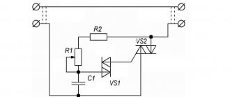
The simplest example of using a PWM voltage regulator is the NE555 PWM chip, which every radio amateur is familiar with. Thanks to its versatility, you can design a wide variety of parts: from the simplest single-shot pulse generator with 2 in the harness to a modulator consisting of a large number of components. The PWM voltage regulator has a wide range of applications - circuits for adjusting the brightness of LEDs and strips, as well as adjusting the rotation speed of motors.
Why is PWM used?
The main reasons for using PWM are the ease of its implementation, for which the backlight only needs the ability to turn on and off frequently, as well as the wide range of possible brightness values provided with its help.
It is possible to reduce the brightness of CCFL backlights by reducing the current flowing through the lamp, but only by about half due to their strict current and voltage requirements. This makes PWM the only simple way to achieve a wide range of dimming. A CCFL lamp is typically controlled by an inverter, switching on and off at a frequency of tens of kilohertz, which is beyond the flicker perceptible to humans. However, PWM typically operates at a much lower frequency, around 175 Hz, which can cause noticeable image artifacts.
The brightness of LED backlights can be adjusted over a wide range by changing the current passing through them, although as a result the color temperature changes slightly. This analogue approach to changing the brightness of LEDs is also undesirable due to the fact that the auxiliary circuits must take into account the heat generated by the LEDs. When turned on, LEDs heat up, which reduces their resistance and further increases the current flowing through them. This can lead to a rapid increase in current in ultra-bright LEDs and cause them to fail. By using PWM, the current can be forced to be held at a constant level during the operating cycle, resulting in the color temperature always being the same and no overcurrent occurring.
Principle of operation
Voltage stabilizer 12 volts
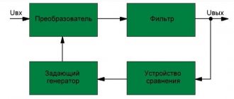
A switching voltage regulator uses the principle of comparing the reference voltage with the output voltage. The circuit allows you to adjust the duration of the key opening. The input voltage from the power source (PS) is passed by the switch according to the control signal of specified parts (pulses), taking into account that the average potential (lowered or increased) was stable.
IC block diagram