Features of operation, ease of inclusion in many circuits and good characteristics have made the TL431 chip a very popular adjustable stabilizer on the market. With a minimal set of additional electronic components (several resistors and capacitors), it is capable of providing operating voltage in the range from 2.5 to 36 V, with a stabilization current from 1 to 100 mA. To obtain large values, powerful transistors are usually added to the TL431 output.
This device is also called a controlled programmable zener diode. It was first introduced to the world by the American company Texas Instruments (TI) back in 1977. Since then, it has been constantly improved and is now an integral part of many modern switching power supplies, where it serves as a reference voltage source. It can be an excellent replacement for Zener diodes in various electronic circuits.
Tsokolevka
The pinout of the TL431 depends on the housing design of the device in which it is placed. There are five varieties in total: for installation in holes: TO-92; for surface mounting: SOT-23, SOT-25, SOT-89 and SOP-8. The electronic circuits inside such plastic packages have only 3 contacts, with the purpose of: 1 – control electrode; 2 – anode; 3- cathode. Some types of housings of this microcircuit have more metal pins, but they are not used or are combined with neighboring ones. How this is done is clearly shown in the figure.
AC models
Cherry AC zener diodes TL431 are often used for dipole inverters. How to check the functionality of the connected element? This can be done using a regular tester. The output resistance parameter must be no more than 70 Ohms
It is also important to note that devices in this series are switched on via a vector converter
In this case, scalar modifications are not suitable. This is largely due to the low threshold of current conduction
It is also important to note that the nominal voltage does not exceed 4 W. The operating current in the circuit is maintained at 2 A
To reduce heat losses, various thyristors are used. Today, expansion and phase modifications are produced.
TL431 Specifications
Let's consider the maximum permissible performance characteristics of the microcircuit. If during its operation they are exceeded, the device will inevitably fail. Long-term operation with parameters close to the limit values is also not allowed. Let's look at them in more detail:
- cathode output voltage (VKA), relative to the anode terminal, up to 37 V;
- possible current values: for continuous cathode output (IKA) from –100 mA to 150 mA; for reverse input from -50 mA to 10 mA;
- typical impedance up to 0.22 Ohm;
- power dissipation (for different types of packaging) PD: 0.8 W (SOT-89); 0.78 W (TO-92); 0.75 W (SO-8); 0.33 W (SOT-23); 0.5 W (SOT-25);
- crystal temperature (TJ): operating: 0…+70 °C; -40 ... +125OS (for some car versions); maximum (TJmax) up to +150°C;
- body thermal resistance RθJC: 97OC/W (D); 156 OS/W (LP); 28 OS/W (KTP); 127OS/W (P); 52OS/W (PK); 149OS/W (PW);
- storage temperature: -65… +150 °C.
The maximum power dissipation can be calculated using the standard formula PD= (TJmax-TA)/ RθJC. In it, TA is the ambient temperature.
Recommended operating parameters
In operating conditions, the recommended values for using the TL413 are: input reference voltage (VREF) no more than 36 V; cathode current (IKA) should be in the range from 1 to 100 mA; compliance with temperature conditions of use. It is worth considering that with IKA <5 mA, this microcircuit may function unstable. Below are the electrical parameters of the device, measured at a temperature of TA = 25°C.
What can be replaced
Today you can replace the device with a domestic or foreign analogue. TL431, TL431A, TL431ACD, TL431ACZ, TL431CLP, TL431CD and others do an excellent job.
The main analogue of the TL 431 pinout is TL431CD
In general, the TL431 pinout is an adjustable zener diode used as a voltage reference in various power supplies. From the very beginning of its release, it was used in computers, laptops and other electronics. The principle of its operation is simple: the operational amplifier opens the transistor and current begins to flow to the anode. It has its own relay, current stabilizer and charger. Analogue equipment is TL431CLP, TL431CD and others.
TL431 connection diagrams
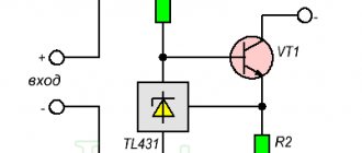
Let's figure out how the TL431 works using the example of a simple stabilization circuit, consisting of a zener diode itself and one resistor. The positive pole of the power supply is connected to the cathode, and the negative pole of the power supply is connected to the anode. To turn on the microcircuit, a reference voltage (Vref) is applied to its control electrode.
If its value is more than 2.5 V, then the zener diode will almost immediately open and begin to pass current through itself (IKA), which can be used to power the corresponding load. Its value will increase as the Vin level increases. IKA can be determined by the formula IKA = (Vin—Vref)/R. In this case, the output voltage of the circuit will be stabilized at the reference level (VKA = Vref), not exceeding 2.5 V and regardless of the Vin supplied at the input.
The maximum IKA value of the TL431 is limited not only by 100 mA, but also by the power dissipation into its housing.
Calculation of a parametric stabilization scheme
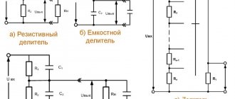
To obtain a higher voltage at the output of the microcircuit (up to 36 V), a resistive divider is additionally connected to its control electrode. It consists of two resistors (R1 and R2) connected between the cathode and anode. In this case, the internal resistance of the zener diode increases by (1 + R1/R2) times.
To calculate the stabilization circuit on the TL431, initial data on the input (VIN) and output (VKA) voltages, as well as currents: stabilization (IKA) and load (IL) are required. With this data, you can calculate the values of other electronic components shown in the figure below.
The output voltage and resistance ratings are related to each other by the following formula VKA= Vref *(1 + R1/R2)+ Iref *R1. Where Vref = 2495 mV and Iref = 2 µA are typical values, they are indicated in the electrical parameters from the datasheet for the device.
Resistance R1 can also be taken from the datasheet. Most often they are taken with ratings from 10 to 30 kOhm. The value of R1 is limited by the small reference current (Iref = 2 µA), which is often neglected for calculations of stabilization circuits on the TL431. Therefore, to calculate the value of R2, without taking into account Iref, you can use the following formula R2=R1/((VKA/Vref)-1).
Stabilization voltage adjustment
To build circuits with the ability to manually adjust the output voltage, a potentiometer is installed instead of the usual R1. The value of the limiting resistor R, which resists the current at the input (IIN), is calculated using the formula R = (VIN-VKA) / IIN. Here IIN = IKA+ IL.
Despite the advantages of the TL431 microcircuit, it also has a very significant drawback - it is a small load current that it can withstand. To solve this problem, powerful bipolar or field-effect transistors are included in the circuit.
Examples of various circuits based on the TL431 zener diode can be seen in the following video.
A simple lithium battery charger.
The main difference between a charger and a power supply is a clear limitation of the charging current. The following circuit has two limiting modes: - current; — by voltage;
As long as the output voltage is less than 4.2 V, the output current is limited; when the voltage reaches 4.2 V, the voltage begins to be limited and the charging current decreases. In the following diagram, current limitation is carried out by transistors VT1, VT2 and resistors R1-R3. Resistor R1 performs the function of a shunt, when the voltage across it exceeds 0.6 V (opening threshold VT1), transistor VT1 opens and closes transistor VT2. Because of this, the voltage at the base of VT3 drops; it begins to close and, consequently, the output voltage decreases, and this leads to a decrease in the output current. This is how current feedback and stabilization works. When the voltage approaches the level of 4.2 V, DA1 begins to come into operation and limit the voltage at the output of the charger.
And now a list of circuit component values:
- DA1 – TL431C;
- R1 – 2.2 Ohm;
- R2 – 470 Ohm;
- R3 – 100 kOhm;
- R4 – 15 kOhm;
- R5 – 22 kOhm;
- R6 – 680 Ohm (needed to adjust the output voltage);
- VT1, VT2 – BC857B;
- VT3 – BCP68-25;
- VT4 – BSS138.
How to check with a multimeter
TL431 cannot be tested with a multimeter as it is not a simple zener diode but an integrated circuit. The resistances between its terminals differ from different manufacturers. Therefore, in order to verify its serviceability, they usually assemble the simplest verification schemes.
To check in the circuit shown in the figure on the left, 12 V is supplied to the input. If the device is working properly, then a voltage of 4.9-5.0 V should appear at the output, and when the S1 button is closed - 2.5 V. A multimeter, in this case, is needed to measure the test results .
The TL431 can also be tested in another LED test circuit (picture on the right). When the resistance R2 of the potentiometer changes, 2.5 V appears on the control electrode. The diode should jump into a glowing state. This will mean that the device is working properly. This operating principle can be used to create a battery discharge indicator.
For car inverters
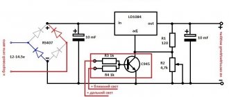
For automotive inverters, AC zener diodes TL431 are often used. The connection circuit in this case involves the use of two-digit triodes. The filters themselves are used in the open type. If we consider circuits without an expander, the threshold voltage fluctuates around 10 W.
The direct operating current is 4 A. The system overload parameter is allowed at 3 mA. If we consider modifications with expanders, then in this case high-capacity modulators are installed. Resistors are used as standard selective type.
In some cases, amplifiers of different power are used. The threshold voltage parameter, as a rule, does not exceed 12 W. The output impedance of the system can range from 70 to 80 ohms. The stabilization accuracy rate is approximately 2%. The operating current of the systems is no more than 4.5 A. The zener diodes are directly connected through the cathode.
Manufacturers
Due to its good parameters, reliability and low cost, TL431 is used in various technical solutions. Therefore, many foreign companies are engaged in its production. There is even a fully translated datasheet tl431 in Russian from Texas Instruments (TI). Here are links to some datasheets of devices sold in the Russian Federation: ON Semiconductor, STMicroelectronics, Nexperia, HTC Korea, NXP Semiconductors. There are still manufacturers of these products, but they are difficult to find in Russian stores. These include: Unisonic Technologies, Motorola, Fairchild Semiconductor, Diodes Incorporated, HIKE Electronics, Calogic, Sangdest Microelectronic (Nanjing), SeCoS Halbleitertechnologie GmbH, Hotchip Technology, Foshan Blue Rocket Electronics, etc.
