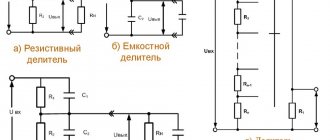
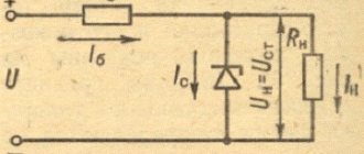
Simple parametric voltage stabilizer
The input voltage Uin must be significantly higher than the stabilization voltage of the zener diode VD1. And so that the zener diode does not fail, the current through it is limited by a constant resistor R1. The output voltage Uout will be equal to the stabilization voltage of the zener diode, but with the output current the situation is more complicated.
The fact is that each zener diode has a certain range of operating current through it, for example, the minimum stabilization current is 5 mA, and the maximum is 25 mA. If we connect a load at the output of such a stabilizer, then part of the current begins to flow through it.
And the maximum value of this current will depend on both resistance R1 and the minimum stabilization current of the zener diode - the maximum load current will be reduced by the minimum stabilization current of the zener diode. That is, it turns out that the lower the resistance R1, the greater the current that can be supplied to the load. At the same time, the current through R1 should not be greater than the maximum stabilization current of the zener diode.
Rice. 1. Circuit of the simplest parametric stabilizer using a zener diode and a resistor.
Since, firstly, the zener diode needs a certain margin to maintain the output voltage stable, and secondly, the zener diode can fail if the maximum stabilization current is exceeded, which can happen when the load is turned off or it is operating in a mode with low current consumption.
A stabilizer according to this scheme is very ineffective and is suitable only for powering circuits that consume a current not exceeding the maximum current of the zener diode. Therefore, stabilizers according to the circuit in Fig. 1 are used only in circuits with a small load current.
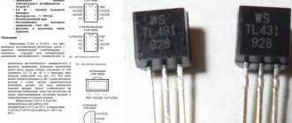
TL431 connection diagrams
The TL431 zener diode microcircuit can be used not only in power circuits. Based on the TL431, you can design all kinds of light and sound signaling devices. With the help of such designs it is possible to control many different parameters. The most basic parameter is voltage control.
By converting some physical indicator into a voltage indicator using various sensors, it is possible to make a device that monitors, for example, temperature, humidity, liquid level in a container, degree of illumination, gas and liquid pressure. Below we present several circuits for connecting the controlled zener diode TL431.
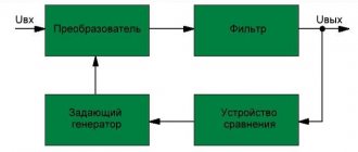
Professional digital oscilloscope
Number of channels: 1, screen size: 2.4 inches, resolution...
More details
Current stabilizer on TL431
This circuit is a current stabilizer. Resistor R2 acts as a shunt, on which a voltage of 2.5 volts is established due to feedback. As a result of this, we obtain a direct current at the output equal to I=2.5/R2.
Overvoltage indicator
The operation of this indicator is organized in such a way that when the potential at the control contact TL431 (pin 1) is less than 2.5 V, the zener diode TL431 is locked, only a small current passes through it, usually less than 0.4 mA. Since this current value is enough for the LED to light up, to avoid this, you just need to connect a 2...3 kOhm resistance in parallel with the LED.
If the potential supplied to the control pin exceeds 2.5 V, the TL431 chip will open and HL1 will start to light up. Resistance R3 creates the desired limitation of the current flowing through HL1 and the zener diode TL431. The maximum current passing through the zener diode TL431 is around 100 mA. But the LED's maximum allowable current is only 20 mA. Therefore, it is necessary to add a current-limiting resistor R3 to the LED circuit. Its resistance can be calculated using the formula:
R3 = (Upit. – Uh1 – Uda)/Ih1
where Upit. - supply voltage; Uh1 – voltage drop across the LED; Uda – voltage on open TL431 (about 2 V); Ih1 – required current for the LED (5...15mA). It is also necessary to remember that for the TL431 zener diode the maximum allowable voltage is 36 V.
The magnitude of the voltage Uz at which the alarm is triggered (the LED lights up) is determined by the divider across resistances R1 and R2. Its parameters can be calculated using the formula:
R2 = 2.5 x Rl/(Uз - 2.5)
If you need to accurately set the response level, then you need to install a trimming resistor with a higher resistance in place of resistance R2. After fine tuning is completed, this trimmer can be replaced with a permanent one.
Sometimes it is necessary to check several voltage values. In this case, you will need several similar signaling devices on the TL431 configured for their own voltage.
Checking the serviceability of TL431
Using the above circuit, you can check the TL431 by replacing R1 and R2 with one 100 kOhm variable resistor. If by rotating the variable resistor slider the LED lights up, then the TL431 is working.
Low voltage indicator
The difference between this circuit and the previous one is that the LED is connected differently. This connection is called inverse, since the LED lights up only when the TL431 chip is locked.
If the monitored voltage value exceeds the level determined by the divider Rl and R2, the TL431 chip opens and current flows through resistance R3 and pins 3-2 of the TL431 chip. At this moment, there is a voltage drop on the microcircuit of about 2V, and it is clearly not enough to light the LED. To completely prevent the LED from burning, 2 diodes are additionally included in its circuit.
At the moment when the value under study is less than the threshold determined by the divider Rl and R2, the TL431 microcircuit will close, and the potential at its output will be significantly higher than 2V, as a result of which the HL1 LED will light up.
Voltage change indicator
If you only need to monitor voltage changes, the device will look like this:
This circuit uses a two-color LED HL1. If the potential is below the threshold set by the divider R1 and R2, then the LED lights up in green, but if it is above the threshold value, then the LED lights up in red. If the LED does not light up at all, this means that the controlled voltage is at the level of the specified threshold (0.05...0.1V).
Working with TL431 sensors
If it is necessary to monitor changes in any physical process, then in this case the resistance R2 must be changed to a sensor characterized by a change in resistance due to external influence.
An example of such a module is given below. To summarize the operating principle, various sensors are shown in this diagram. For example, if you use a phototransistor as a sensor, you will end up with a photo relay that responds to the degree of illumination. As long as the illumination is high, the resistance of the phototransistor is low.
As a result, the voltage at the control contact TL431 is below the specified level, which is why the LED does not light up. As illumination decreases, the resistance of the phototransistor increases. For this reason, the potential at the control contact of the zener diode TL431 increases. When the response threshold (2.5V) is exceeded, HL1 lights up.
This circuit can be used as a soil moisture sensor. In this case, instead of a phototransistor, you need to connect two stainless electrodes, which are stuck into the ground at a short distance from each other. After the soil dries, the resistance between the electrodes increases and this causes the TL431 chip to operate and the LED lights up.
If you use a thermistor as a sensor, you can make a thermostat from this circuit. The circuit's response level in all cases is set by resistor R1.
TL431 in circuit with sound indication
In addition to the above lighting devices, you can also make a sound indicator on the TL431 chip. A diagram of such a device is shown below.
This sound alarm can be used to monitor the water level in any container. The sensor consists of two stainless electrodes located at a distance of 2-3 mm from each other.
As soon as water touches the sensor, its resistance will decrease, and the TL431 chip will enter linear operating mode through resistances R1 and R2. In this regard, self-generation appears at the resonant frequency of the emitter and a sound signal will be heard.
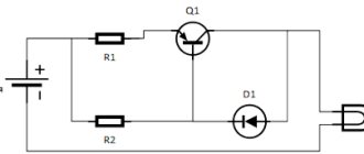
Voltage stabilizer using a transistor
If you need to provide a more or less significant load current and reduce its effect on stability, you need to enhance the output current of the stabilizer using a transistor connected according to the emitter follower circuit (Fig. 2).
Rice. 2. Circuit of a parametric voltage stabilizer using one transistor.
The maximum load current of this stabilizer is determined by the formula:
In = (Ist - Ist.min)*h21e.
where Ist. is the average stabilization current of the zener diode used, h21e is the current transfer coefficient of the base of transistor VT1.
For example, if we use a KS212Zh zener diode (average stabilization current = (0.013-0.0001) / 2 = 0.00645A), a KT815A transistor with h21 e - 40), we can get no more current from the stabilizer according to the circuit in Fig. 2: ( 0.006645-0.0001) * 40 = 0.254 A.
In addition, when calculating the output voltage, you need to take into account that it will be 0.65V lower than the stabilization voltage of the zener diode, because the silicon transistor drops about 0.6-0.7V (approximately take 0.65V).
Let's try to calculate the stabilizer according to the diagram in Figure 2.
Let's take the following initial data:
- Input voltage Uin = 15V,
- output voltage Uout = 12V,
- maximum current through the load In = 0.5A.
The question arises, what to choose - a zener diode with a large average current or a transistor with a large h21e?
If we have a KT815A transistor with h21e = 40, then, following the formula In = (Ist -Ist.min) * h21e, we will need a zener diode with a difference between the average current and the minimum current of 0.0125A.
In terms of voltage, it should be 0.65V greater than the output voltage, that is, 12.65V. Let's try to find it from the reference book.
Here, for example, is a KS512A zener diode, its stabilization voltage is 12V, the minimum current is 1 mA, the maximum current is 67 mA. That is, the average current is 0.033A. In general it is suitable, but the output voltage will not be 12V, but 11.35V.
We need 12V. It remains to either look for a 12.65V zener diode, or compensate for the lack of voltage with a silicon diode, connecting it in series with the zener diode as shown in Figure 3.
Fig.3. Schematic diagram of a parametric voltage stabilizer, supplemented with a diode.
Now we calculate the resistance R1:
R = (15 -12) / 0.0125A = 240 Ohm.
A few words about choosing a transistor based on power and maximum collector current. Maximum collector current Ik.max. must be no less than the maximum load current. That is, in our case, no less than 0.5A.
And the power should not exceed the maximum permissible. You can calculate the power that will be dissipated by the transistor using the following formula:
P = (Uin - Uout) * Iout.
In our case, P = (15-12)*0.5=1.5W.
Thus, Ik.max. transistor must be at least 0.5A, and Pmax. at least 1.5W. The selected transistor KT815A is suitable with a large margin (Ik.max.=1.5A, Pmax.=10W).