A thyristor battery charger has a number of advantages. This circuit allows you to safely charge any 12 V car battery, without the risk of boiling.
Additionally, devices of this type are suitable for restoring lead-acid batteries. This is achieved by monitoring charging parameters, which means the ability to simulate recovery modes.
A common, simple, but very effective thyristor phase-pulse power regulator circuit has long been used to charge lead-acid batteries.
Find out the charging time of your battery
Charging on KU202N allows:
- achieve charging current up to 10A;
- produce a pulse current that has a beneficial effect on the life expectancy of the battery;
- assemble the device yourself from inexpensive parts available at any radio electronics store;
- repeat the circuit diagram even for a beginner who is superficially familiar with the theory.
Conventionally, the presented scheme can be divided into:
- A step-down device is a transformer with two windings that converts 220V from the network into 18-22V, which is necessary for the operation of the device.
- The rectifier unit that converts the pulse voltage into a permanent one is assembled from 4 diodes or implemented using a diode bridge.
- Filters are electrolytic capacitors that cut off alternating components of the output current.
- Stabilization is carried out using zener diodes.
- The current regulator is produced by a component built on transistors, thyristors and variable resistance.
- Monitoring of output parameters is realized using an ammeter and a voltmeter.
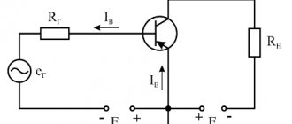
Principle of operation
A circuit of transistors VT1 and VT2 controls the thyristor electrode. The current passes through VD2, which protects against return pulses. The optimal charging current is controlled by component R5. In our case, it should be equal to 10% of the battery capacity. To monitor the current regulator, this parameter must be installed in front of the connection terminals with an ammeter.
This circuit is powered by a transformer with an output voltage of 18 to 22 V. It is imperative to place the diode bridge, as well as the control thyristor, on the radiators to remove excess heat. The optimal radiator size should exceed 100cm2. When using diodes D242-D245, KD203, be sure to isolate them from the device body.
This thyristor charger circuit must be equipped with a fuse for the output voltage. Its parameters are selected according to your own needs. If you do not intend to use currents greater than 7 A, then a 7.3 A fuse will be sufficient.
Features of assembly and operation
Theristor testing circuit
The charger assembled according to the presented diagram can later be supplemented with automatic protective systems (against polarity reversal, short circuit, etc.). Particularly useful, in our case, will be the installation of a system for cutting off the current supply when charging the battery, which will protect it from overcharging and overheating.
It is advisable to equip other protective systems with LED indicators that indicate short circuits and other problems.
Monitor the output current carefully as it may vary due to line fluctuations.
Like similar thyristor phase-pulse regulators, a charger assembled according to the presented circuit interferes with radio reception, so it is advisable to provide an LC filter for the network.
Thyristor KU202N can be replaced with similar ones KU202V, KU 202G or KU202E. You can also use the more productive T-160 or T-250.
DIY thyristor charger
To assemble the presented circuit yourself, you will need a minimum of time and effort, along with low costs for components. Most of the components can be easily replaced with analogues. Some parts can be borrowed from failed electrical equipment. Before use, the components should be checked, thanks to this, a charger assembled even from used parts will work immediately after assembly.
Unlike models on the market, the performance of a self-assembled charger is maintained over a larger range. You can charge a car battery from -350C to 350C. This and the ability to regulate the output current, giving the battery a large amperage, allows in a short time to compensate the battery for a charge sufficient to turn the starter on the engine.
Thyristor chargers have a place in car enthusiasts' garages due to their ability to safely charge a car battery. The schematic diagram of this device allows you to assemble it yourself using products from the radio market. If knowledge is not enough, you can use the services of radio amateurs who, for a fee that is several times less than the cost of a store-bought charger, will be able to assemble the device for you according to the diagram provided to them.
The use of thyristor chargers is justified - restoration of battery functionality occurs much faster and more “correctly”. The optimal value of the charging current and voltage is maintained, so it is unlikely to harm the battery. After all, overvoltage can cause the electrolyte to boil away and destroy the lead plates. And all this leads to failure. But you need to remember that modern lead batteries can withstand no more than 60 full discharge and charge cycles.
Self-production of simple chargers made on a thyristor
Any experienced car owner almost certainly has a charger (charger) in their garage or home. The highest quality type involves smooth regulation of current and output voltage. It will not be possible to do this with step switches; the best option is to use an electronic circuit, where the main role is played by a thyristor - a component that changes U and I in the load. However, store-bought devices are quite expensive, and if you have skills in working with a soldering iron and knowledge in the field of radio engineering, you can design a charger using a thyristor yourself, which will cost an order of magnitude cheaper.
- The principle of phase-pulse power control using a thyristor
- DIY thyristor charger
- Selection of the scheme and principle of its operation
- List of components in the circuit and selection of possible analogues
- Calculation of transformer, thyristor and diode parameters
- Disadvantages of thyristor memory
General description of the charger circuit
Anyone can make thyristors if they have knowledge of electrical engineering. But in order to do all the work correctly, you need to have at least the simplest measuring device on hand - a multimeter.
It allows you to measure voltage, current, resistance, and check the performance of transistors. And there are the following functional blocks:
- A step-down device - in the simplest case, it is a regular transformer.
- The rectifier block consists of one, two or four semiconductor diodes. A bridge circuit is usually used because it produces almost pure direct current without ripple.
- A filter bank is one or more electrolytic capacitors. With their help, the entire alternating component in the output current is cut off.
- Voltage stabilization is carried out using special semiconductor elements - zener diodes.
- An ammeter and a voltmeter monitor current and voltage, respectively.
- The output current parameters are adjusted by a device assembled using transistors, a thyristor and a variable resistance.
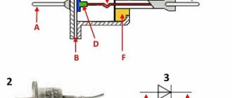
What is a unijunction transistor. How does it work and several circuits on it
In old TVs, you can find a KT117 transistor on the switching power supply board. This is a unijunction transistor. I have never seen any other such transistors, except KT117. Such transistors are called a double-base diode and are used in pulse generator circuits; they do not serve to amplify the signal or operate at high frequencies.
This transistor can be imagined as a plate with two base terminals with an n-region (electrons), in the middle of this plate there is a p-region (holes). The plate has a high resistance and if you connect a load - a low-power lamp, the current will not flow through the lamp or is insignificant, there is no movement of electrons. If you apply voltage to the p-region up to a certain value, holes will begin to flow sharply from this region into the n-region of electrons, current will flow through the n-region and the lamp will flash. We remove the voltage from the p-region, the lamp will go out. Now let's turn on a capacitor that will be charged and discharged through the lamp, then we get a simple flasher. So we have a generator. This is similar to the operation of a dinistor, so the dinistor has replaced the unijunction transistor from thyristor control circuits at high voltages.
Operating parameters: interbase resistance; on-off current; operating and off voltage.
Instead of a lamp, a 100 Ohm resistor is connected. The signal on this resistor will be as shown in the photo.
Such a saw signal will be on the capacitor.
An adjustable sound generator based on a unijunction transistor. By changing the resistance of resistor R3 and applying different voltages to the capacitor, you can change the tone of the sound in the speaker.
Using the KT117 transistor, you can assemble a thyristor control circuit to control the rotation of an electric motor, change the brightness of an incandescent lamp, etc. The circuit is powered by a 12V step-down transformer; after the diode bridge, a filter capacitor is not needed, this is what the operation of this circuit is based on.
Source
The main element is a transformer
There’s simply no way without it; it’s impossible to make a thyristor-controlled charger without using a transformer. The purpose of using a transformer is to reduce the voltage from 220 V to 18-20 V. This is exactly what is needed for normal operation of the charger. General design of the transformer:
- Magnetic core made of steel plates.
- The primary winding is connected to a 220 V AC source.
- The secondary winding is connected to the main board of the charger.
Some designs may use two secondary windings connected in series. But in the design discussed in the article, a transformer is used, which has one primary and the same number of secondary windings.
Simple charger for car batteries
An easy-to-replicate charger with adjustable charging current using the pulse-phase control method of a thyristor is proposed.
The device diagram is shown in the figure. Setting the required charging current from 0 to 10 A is carried out in a known way: by changing the opening delay of the control element - the SCR - after the moment the alternating supply voltage passes through zero. After connecting the XP1 plug to the network and closing the SA1 switch, a voltage of 220 V, 50 Hz is supplied through the fuse link FU1 to the primary winding of the step-down transformer T1. Capacitor C1 is noise suppressing. Neon lamp HL1 – indicator of the presence of mains voltage. The voltage from the secondary winding, composed of six sections connected in series, is supplied to the diode bridge VD1-VD4 and diodes VD5, VD6. The voltage rectified by the diode bridge is supplied through the ammeter PA1 and the fuse-link FU2 to the positive terminal of the battery being charged, and through the regulating element - the thyristor VS1 to the negative terminal. The rectified voltage from the cathodes of diodes VD5, VD6 and the negative terminal of the bridge VD1-VD4 is supplied to the voltage limiter, and through resistor R2 to the LED HL2. The glow of the latter indicates the presence of voltage on the secondary winding of transformers T1. The limiter is assembled using a zener diode VD7 and resistor R3. From its output, a voltage close to a trapezoidal shape (half-sine wave with cut off vertices) and a frequency of 100 Hz is supplied to the control unit of the trinistor VS1. It is a pulse generator based on a unijunction transistor VT1. Variable resistor R4, resistor R5 and capacitor C2 are the timing circuit of the generator. With the beginning of each trapezoidal pulse, formed, as indicated above, by the zener diode VD7 and resistor R3, charging of capacitor C2 begins through resistors R4, R5. Unijunction transistor VT1 is closed. When capacitor C2 reaches the turn-on voltage of the microcircuit, capacitor C2 is discharged through the circuit section emitter - base 1 of transistor, resistor R6. The pulse on resistor R6 opens the thyristor VS1, and the voltage from the diode bridge VD1-VD4 is supplied to the battery being charged. The duration of this voltage supply is the difference between the duration of the half-cycle of the network voltage (10 ms) and the delay in turning on the SCR from the beginning of the half-cycle (the passage of the network voltage through zero). When the variable resistor R4 slider is moved to the left according to the circuit, the SCR will open closer to the end of each trapezoidal pulse arriving at the control unit, and the charging current will be less. On the contrary, when you move the resistor slider to the right, the charging current will increase.
Structurally, the device can be placed either in a home-made case or in a ready-made one, for example, from some device that has served its useful life. Cases from devices B3-38 - B3-41, B3-47, B3-57 are very suitable, which can be easily modified by replacing the front panel and drilling the required number of ventilation holes to ensure cooling of the device.
Fuse link FU1-VP1-1 5 A, 250 V. It is not recommended to use a link with a lower current, as it will systematically burn out when the device is turned on. Insert FU2 - VP3B for 10 A. Switch SA1 type T3 can be replaced with a key switch with light indication, for example, R59-2 [1], while elements R1 and HL1 are excluded. Capacitor C1 - K73-17 for a voltage of 630 V. Its capacitance can be in the range of 0.01...0.22 µF. This capacitor is soldered directly to terminals 1 and 6 of transformer T1. Capacitor C2 - any with a voltage of at least 25 V.
Transformer T1 is a unified TPP320-127/220-50 [2] with a power of 220 W. It can be replaced with TPP318-127/220-50 or TPP310-127/220-50, the winding connection circuit is identical.
It is possible to use the TPP323-127/220-50 transformer, in which case the windings with pins 11-12, 13-14, 18-17, 20-19 must be connected in parallel, i.e., solder together pins 11, 13, 18, 20 and 12, 14, 17, 19.
The secondary windings of this transformer can be connected in another way by making a rectifier according to the usual full-wave circuit. In this case, instead of the diode bridge VD1-VD4, only two diodes are installed. Windings with terminals 11-12, 13-14 should be connected in parallel, windings with terminals 18-17, 20-19 should also be connected in parallel, i.e. terminals 11, 13 should be together; 12, 14; 14, 17; 19 and 18, 20, and then connect pin 14 to pin 18 - this will be the middle point and the negative terminal of the rectifier. The extreme terminals 11, 13 and 19, 17 are soldered to the anodes of powerful rectifier diodes.
You can also use a network transformer from an old color tube TV. First you need to remove all its secondary windings, while counting the number of turns of the filament winding. Next, on each of the two frames, a new secondary winding is wound with a wire with a cross-section of at least 3 mm2 in any heat-resistant insulation with a number of turns three times greater than incandescent.
After assembling the transformer, the coils are connected in series. If there is no wire of the required cross-section, you can use a bundle of thinner wires, weaving them into a braid [3]. Before installing a homemade transformer, it is necessary to check the insulation resistance between the primary and secondary windings - it must be at least 20 MOhm. Otherwise, you should dry the transformer in a warm, dry place and measure the insulation resistance again, and if it is again less than 20 MOhm, then it is better not to use such a transformer.
D214 diodes can be replaced by any with a forward current of at least 10 A and a reverse voltage of at least 100 V. They are installed on heat sinks with a surface area of at least 50 cm2. Diodes VD5, VD6 – any low-power silicon ones. We can replace the thyristor with any one from the KU202 series or a more powerful one, for example, from the T122 series (T122-20, etc.) [4]. It is installed on a heat sink with an area of at least 100 cm2. We will replace the KT117A transistor with KT117B, KT117G; KT132A, KT132B; KT133A, KT133B or imported 2N2646, 2N2647, 2N4870, 2N4871. Instead of a unijunction transistor, its transistor analogue can be used. Ammeter PA1 and voltmeter PV1 - M4202, M4203. Fixed resistors - any type. Variable resistor R4 with linear characteristic. Its resistance can be from 100 to 680 kOhm. In this case, you will need to select the capacitance of capacitor C2 so that the time constant R4C2 remains the same. The resistor terminals must be connected so that when the handle is rotated clockwise, the introduced resistance decreases.
No printed circuit board was developed. A correctly assembled device does not require adjustment. However, before turning it on for the first time, instead of fuse link FU1, you should connect a 220 V incandescent lamp with a power of 100...150 W. When you turn on SA1, the lamp should flash and go out. If it burns at almost full intensity, you should check the correct connection of the transformer windings and the presence of short circuits in the secondary circuit. Next, turning the variable resistor knob to the extreme counterclockwise (initial) position, connect a 12 V 15 W car lamp in parallel with the voltmeter PV1. It shouldn't glow. By smoothly rotating the variable resistor knob clockwise, you should make sure that the lamp lights up and its brightness increases to full when the voltmeter readings are about 15 V. It may be necessary to adjust the capacitance of capacitor C2. When operating the device, before connecting the load, the handle of the variable resistor R4 should always be set to the initial position.
Literature
- Yushin A. Key switches with light indication. – Radio, 2005, No. 5, p. 52.
- Unified transformers - Radio, 1982, No. 1, p. 59, 60.
- Kobelev F. G. How to make welding machines with your own hands. – Petersburg: Science and Technology, 2011, p. 156.
- Thyristors (Technical reference book). Per. from English, ed. Labuntsova V. A., Obukhova S. P., Sviridova A. F. Ed. 2nd add. – M.: Energy, 1971, p. 111-118.
Authors: A. KVAKINA, P. MIKHEEV, Zheleznogorsk, Krasnoyarsk Territory
Rough calculation of transformer windings
It is advisable to use a transformer with an existing primary winding in the design of a thyristor charger. But if there is no primary winding, you need to calculate it. To do this, it is enough to know the power of the device and the cross-sectional area of the magnetic circuit. It is advisable to use transformers with a power of over 50 W. If you know the cross-section of the magnetic circuit S (sq. cm), you can calculate the number of turns for every 1 V of voltage:
N = 50 / S (sq. cm).
To calculate the number of turns in the primary winding, you need to multiply 220 by N. The secondary winding is calculated in a similar way. But you need to take into account that in a household network the voltage can jump up to 250 V, so the transformer must withstand such changes.
Winding and assembly of the transformer
Before you start winding, you need to calculate the diameter of the wire that you will need to use. To do this you need to use a simple formula:
d = 0.02×√I (windings).
The wire cross-section is measured in millimeters, the winding current is measured in milliamps. If you need to charge with a current of 6 A, then substitute the value of 6000 mA under the root.
Having calculated all the parameters of the transformer, you begin winding. Lay the coil evenly to the coil so that the winding fits in the window. Fix the beginning and end - it is advisable to solder them to free contacts (if any). Once the winding is ready, you can assemble the transformer steel plates. Be sure to coat the wires with varnish after winding is completed, this will help get rid of the humming noise during operation. The core plates can also be treated with an adhesive solution after assembly.
PCB manufacturing
To make a printed circuit board on a thyristor yourself, you need to have the following materials and tools:
- Acid for cleaning the surface of foil material.
- Solder and tin.
- Foil textolite (getinax is more difficult to obtain).
- Small drill and drill bits 1-1.5 mm.
- Ferric chloride. It is much better to use this reagent, since with its help excess copper is removed much faster.
- Marker.
- Laser printer.
- Iron.
Before starting installation, you need to draw the tracks. It is best to do this on a computer, then print the drawing on a printer (necessarily laser).
Printing should be done on a sheet from any glossy magazine. The drawing is translated very simply - the sheet is heated with a hot iron (without fanaticism) for several minutes, then cools down for a while. But you can also draw paths by hand with a marker, and then place the PCB in the solution for a few minutes.
Purpose of memory elements
The device is based on a phase-pulse regulator on a thyristor. There are no scarce components in it, so if you install serviceable parts, the entire circuit will be able to work without adjustment. The design contains the following elements:
- Diodes VD1-VD4 are a bridge rectifier. They are designed to convert alternating current into direct current.
- The control unit is assembled on unijunction transistors VT1 and VT2.
- The charging time of capacitor C2 can be adjusted by variable resistance R1. If its rotor is shifted to the extreme right position, the charging current will be highest.
- VD5 is a diode designed to protect the thyristor control circuit from reverse voltage that occurs when turned on.
This scheme has one big drawback - large fluctuations in the charging current if the network voltage is unstable. But this is not a hindrance if a voltage stabilizer is used in the house. You can assemble a charger using two thyristors - it will be more stable, but it will be more difficult to implement this design.
Description of the thyristor memory
A thyristor charger is a device with electronic control of the charging current. Such devices are produced on the basis of a thyristor power regulator, which is phase-pulse. There are no scarce components in a memory device of this type, and if all its parts are intact, then it will not even have to be configured after manufacturing.
Using such a charger, you can charge a vehicle battery with a current from zero to ten amperes. In addition, it can be used as a regulated power source for certain devices, for example, a soldering iron, a portable lamp, etc. In its form, the charging current is very similar to pulsed, and the latter, in turn, allows you to extend the battery life. The use of a thyristor charger is allowed in the temperature range from -35 to +35 degrees.
Scheme
If you decide to build a thyristor charger with your own hands, you can use many different circuits. Let's consider the description using the example of circuit 1. The thyristor charger in this case is powered from winding 2 of the transformer unit through the diode bridge VDI + VD4. The control element is designed as an analogue of a unijunction transistor. In this case, using a variable resistor element, you can regulate the time during which the capacitor component C2 will be charged. If the position of this part is to the far right, then the charging current will be the highest, and vice versa. Thanks to the diode VD5, the control circuit of the thyristor VS1 is protected.
Advantages and disadvantages
The main advantage of such a device is high-quality charging with current, which will not destroy, but increase the service life of the battery as a whole.
If necessary, the memory can be supplemented with all sorts of automatic components designed for the following options:
- the device will be able to turn off automatically when charging is complete;
- maintaining optimal battery voltage in case of long-term storage without use;
- another function that can be regarded as an advantage - the thyristor charger can inform the car owner whether he has connected the battery polarity correctly, and this is very important when charging;
- also, if additional components are added, another advantage can be realized - protecting the node from output short circuits (video author - Blaze Electronics channel).
As for the shortcomings themselves, these include fluctuations in the charging current if the voltage in the household network is unstable. In addition, like other thyristor regulators, such a charger can create certain interference with signal transmission. To prevent this, it is necessary to additionally install an LC filter during the manufacture of the memory. Such filter elements are, for example, used in network power supplies.
Read also: GOST stud strength classes
Installation of elements on a printed circuit board
It is advisable to mount the diodes and thyristor on separate radiators, and be sure to isolate them from the housing. All other elements are installed on the printed circuit board.
It is undesirable to use wall-mounted installation - it looks too unsightly and is dangerous. To place elements on the board, you need:
- Drill holes for the legs with a thin drill.
- Tin all printed tracks.
- Cover the tracks with a thin layer of tin, this will ensure reliable installation.
- Install all elements and solder them.
After installation is complete, you can coat the tracks with epoxy resin or varnish. But before that, be sure to connect the transformer and the wires that go to the battery.
Final assembly of the device
After installing the charger on the KU202N thyristor, you need to find a suitable housing for it. If there is nothing suitable, make it yourself. You can use thin metal or even plywood. Place the transformer and radiators with diodes and thyristor in a convenient place. They need to be well cooled. For this purpose, you can install a cooler in the rear wall.
You can even install a circuit breaker instead of a fuse (if the dimensions of the device allow). On the front panel you need to place an ammeter and a variable resistor. Having assembled all the elements, you begin testing the device and its operation.
Compact thyristor charger
Figure 1 shows a diagram of a simple charger for a car battery.
Fig. 1 When a certain voltage value is reached (set by the circuit R2, V1, V2), the charger on the thyristor disconnects it from the battery. The reference voltage on the battery is compared at each positive half-cycle while the thyristor is closed. When the battery is discharged, the thyristor opens at the moments of each positive half-cycle with some delay, but only as the battery is close to being fully charged, the thyristor will open with a greater delay and when a certain value is reached, when the battery is fully charged, the thyristor will stop opening. The voltage comparison takes place in the thyristor control electrode circuit. The voltage at the thyristor output depends on its parameters, so it is possible to select a thyristor if the voltage of 13.5V turns out to be slightly underestimated. Any transformer for a voltage in the secondary winding of 20V based on the value of the charging current.
Bornovolokov E.P., Florov V.V. Amateur radio circuits - 3rd edition, revised. and additional - K.: Technology, 1985
Automatic charger
Figure 2 shows a diagram of an automatic charger that allows you to charge a car battery when discharged and stop charging when the battery is fully charged. It is advisable to use such a device for batteries that are stored for a long time.
Fig.2
Switching to charging mode is done by measuring the voltage at the battery terminals. Charging begins when the voltage at the battery terminals drops below 11.5 V and stops when it reaches 14 V.
The op amp in the circuit serves as a precision voltage comparator that monitors the battery voltage level. Its inverting input receives a reference voltage of 1.8 V, and a battery voltage of about 2 V is supplied to the non-inverting input through a divider (when the battery is fully charged). In this case, the relay is disabled because the op-amp output is at a high voltage level. When the voltage drops at the battery terminals, the voltage at the non-inverting input of the op-amp becomes 1.8 V, the comparator switches, this leads to the relay turning on, and the battery begins to charge.
After assembling the charger, it must be adjusted:
1. Discharge the battery to a voltage of 11.5 V 2. Connect the charger to the battery 3. Adjust R6 until the relay is activated 4. When charging the battery, measure the voltage at its terminals, when it reaches 14 V, adjust the potentiometer R5 until the relay turns off If necessary repeat the setup process
Charger for LM317
Fig.3
Based on the LM317 stabilizer, you can make a simple and effective charger. The proposed device is designed for charging 12 V batteries. The maximum charging current is 1.5A. The charging current can be adjusted using potentiometer R5. As the battery charges, the charger reduces the charging current. The LM317 stabilizer must be installed on the radiator.
Charge current indication unit
If your car battery charger does not have an ammeter, it is difficult to ensure reliable charging. There may be deterioration (loss) of the contact on the batteries, which is quite difficult to detect. Instead of an ammeter, a simple indicator is proposed in Fig. 4. It is connected to the gap in the “positive” wire from the charger to the battery.
Fig.4
The circuit is a transistor switch VT1, which turns on the LED HL1 when charging current flows through R1. In this case, the voltage drop across resistor R1 (more than 0.6V) is sufficient to open transistor VT1 to ignite HL1. For a specific battery, the R1 rating is selected so that the LED lights up at the required charging current. By the brightness of its glow, you can approximately estimate the charging current. Resistor R1 is a wire-wound resistor, made from 6…12 turns of winding wire with a diameter of 1 mm. You can use wire with high resistivity (nichrome) or an industrial resistor, for example, PEVR-10.
Charger with car voltage regulator
A simple charger, shown in Fig. 5, will serve to charge the battery and keep it in working condition for a long time.
Fig.5
From the secondary winding of transformer T1, the current in which is limited by being connected in series with the primary winding of the ballast capacitor (C1 or C1 + C2), the current is supplied to the diode-thyristor bridge, the load of which is the battery (GB 1). An automotive 14 V generator voltage regulator (GVR) of any type, intended for generators with a grounded brush, is used as a regulating element. Thus, the battery maintains a voltage of 14 V at a charging current determined by the capacitance of capacitor C2, which is approximately calculated by the formula:
3200. I z. U 2
C (uF) = ————— ——— ,
U 1 2
where Iz is the charging current (A), U 2 is the voltage of the secondary winding when the transformer is “normally” turned on (V), U 1 is the mains voltage.
The device requires virtually no setup. You may need to check the capacitance of the capacitor by monitoring the current with an ammeter. In this case, it is necessary to short-circuit terminals 15 and 67 (B, V and Sh).
From railway (RL 5-99)
Reversing attachment for the charger
This attachment, the circuit of which is shown in Fig. 6, is made on a powerful composite transistor and is intended for charging a car battery with a voltage of 12V alternating asymmetric current. This ensures automatic training of the battery, which reduces its tendency to sulfate and extends its service life. The set-top box can work together with almost any full-wave pulse charger that provides the required charging current.
Fig.6
When the output of the set-top box is connected to the battery (the charger is not connected), when capacitor C1 is still discharged, the initial charging current of the capacitor begins to flow through resistor R 1, the emitter junction of transistor VT 1 and resistor R 2. Transistor VT 1 opens, and a significant battery discharge current, quickly charging capacitor C1. With an increase in the voltage on the capacitor, the battery discharge current decreases to almost zero.
After connecting the charger to the input of the set-top box, a battery charging current appears, as well as a small current through resistor R 1 and diode VD 1. In this case, transistor VT 1 is closed, since the voltage drop across the open diode VD 1 is not enough to open the transistor. Diode VD 3 is also closed, since the reverse voltage of the charging capacitor C1 is applied to it through diode VD 2.
At the beginning of the half-cycle, the output voltage of the charger is added to the voltage on the capacitor, and the battery is charged through the diode VD 2, which leads to the return of the energy accumulated by the capacitor to the battery. Next, the capacitor is completely discharged and diode VD 3 opens, through which the battery now continues to charge. A decrease in the output voltage of the charger at the end of the half-cycle to the level of the battery EMF and below leads to a change in the polarity of the voltage on the diode VD 3, closing it and stopping the charging current.
In this case, transistor VT 1 opens again and a new impulse occurs in discharging the battery and charging the capacitor. With the beginning of a new half-cycle of the charger's output voltage, the next battery charging cycle begins.
The amplitude and duration of the battery discharge pulse depend on the values of resistor R2 and capacitor C1. They are selected according to the recommendations.
The transistor and diodes are placed on separate heat sinks with an area of at least 120 cm 2 each.
In addition to the KT827A transistor indicated in the diagram, you can use KT827B, KT827V. The set-top box can use transistors KT825G - KT825E and diodes KD206A, but the polarity of the diodes, capacitor, as well as the input and output terminals of the set-top box must be reversed.
Fomin.V
Nizhny Novgorod
Simple automatic charger
A typical charger for charging starter batteries consists of a transformer, the winding of which has taps, a diode half-wave rectifier and an ammeter that measures the charging current. Such a charger cannot control the charging process and cannot restore sulfated batteries.
Fig.7
If at the output of such a charger you turn on a node, the diagram of which is shown in Fig. 7, then the device will become automatic and learn to restore the batteries with a training current.
When the battery is connected, the thyristor opens only on positive half-cycles of the pulsating voltage. On the negative side (when the rectifier diode of the charger is closed), the thyristor is closed and a training discharge of the battery occurs through resistor R 3.
At the beginning of each half-cycle, even before the thyristor opens, the voltage on the battery is measured. If this is the voltage of a fully charged battery (13.5 V), then the zener diode opens and prevents the thyristor from opening.
As the battery charges, the thyristor opens closer to the top of the pulsating voltage. The closing of the thyristor occurs at the decline of the half-wave of the pulsating voltage, when this voltage becomes lower than the voltage on the battery.
Karavkin V.
Literature:
Vasiliev V.
"Charger"
and. Radio No. 3 1976
Car battery recharging device
If the car sits idle for a long time, its battery gradually discharges. This is especially felt when storing a car in unheated garages in the winter - at subzero temperatures. Starting the engine involves searching for a starting device from familiar car enthusiasts or trying to get a charged battery from them for temporary use. A car battery recharger can help avoid this problem. The simplicity of the circuit and the absence of scarce radio components make it accessible for repetition.
It is well known that all chemical current sources are subject to self-discharge. The degree of self-discharge depends on a number of reasons. The reasons due to the design features of the batteries are not discussed in this article - motorists have to use the batteries that are on their vehicles. The technological (for cars) reason for battery discharge is due to the storage conditions of the battery. Both the service life of the battery and the degree of its readiness to work in the electrical equipment of the car will depend on this.
The self-discharge current of car batteries largely depends on the “age” of the battery. Approximately, we can assume that the self-discharge current of a battery when stored in an unheated room or outdoors is up to 180 mA. Approximately this battery charging current will ensure its constant readiness for operation.
In the circuit (Fig. 8), low-power transformer TR 1 reduces the voltage of 220 V to approximately 12 V.
Fig.8
The alternating voltage is rectified by bridge rectifier D 1 and supplied through resistor R 3 to the “OUT” output. It is possible to use the XR 1 car plug, which can be inserted into the car's cigarette lighter socket. When power is applied to the circuit, the green LED D 2 lights up.
When charging current flows to the car battery, a voltage drop is created across resistor R 3. When applied to the base of transistor T1 through resistor R 4, this voltage causes saturation of the transistor and LED D 3 (RED) lights up.
Yakovlev E.L.
Uzhgorod
(“Radioamator” No. 12, 2009)
Battery charger
In the absence of a full-fledged charger, a fairly simple rectifier can be made according to the simple circuit in Fig. 9.
Fig.9
It cannot replace a full-fledged charger, since the charging current is only 0.4 ... 0.5 A, but it is quite suitable for, for example, bringing the battery to the working state that was lost in 2 ... 3 days during the months of winter inactivity. The rectifier is assembled on four silicon diodes. A 220V lamp with a power of 70...100 W is connected in series with them, limiting the charging current. The circuit can use diodes having a maximum permissible reverse voltage of at least 400 V and an average rectifying current of at least 0.4 A. Diodes D7Zh, D226, D226D, D237B, D231, D231B, D232 or others with similar characteristics are suitable.
When working with the rectifier, care should be taken, since all its parts are connected directly to the electrical network through the lamp and therefore touching them is dangerous. If the rectifier is connected to the network, then you should not even touch the battery case, as it may be covered with a thin film of electrolyte - a conductor of electric current. If it is necessary to measure the voltage or density of the electrolyte in the battery, the rectifier must be disconnected from the network.
Gornushkin Yu.
“Practical advice for a car owner”
Simple charger
The circuit is a simple transformerless power supply that produces a constant voltage of 14.4 V, with a current of up to 0.4 A. (Fig. 10)
Fig.10
The design is simple and is used to recharge a battery that has been stored for a long time.
As practice shows, restoration requires a small current, about 0.1-0.3 A (for 6ST-55). If the stored battery is periodically, approximately once a month, recharged for 2-3 days, then you can be sure that it will be ready for use at any time, even after several years of such storage (practically tested).
The source is built according to the circuit of a parametric stabilizer with capacitive ballast resistance. The voltage from the mains is supplied to the bridge rectifier VD 1 ... VD 4 through capacitor C 1. At the output of the rectifier, a 14.4 V zener diode VD 5 is switched on. Capacitor C 1 dampens excess voltage and limits the current to no more than 0.4 A. Capacitor C 2 smoothes out the ripples of the rectified voltage. The battery is connected in parallel with VD 5.
The device works as follows. When the battery self-discharges to a voltage below 14.4 V, its “soft” charging begins with a weak current, and the value of this current is inversely dependent on the voltage on the battery. But in any case (even with a short circuit) it does not exceed 0.4 A. When charging the battery to a voltage of 14.4 V, the charging current stops altogether.
The device uses: capacitor C 1 - paper BMT or any non-polar one for 3...5 μF and a voltage of at least 300 V, C2 - K50-3 or any electrolytic for 100...500 μF, for a voltage not lower than 25 V; rectifier diodes VD 1... VD 4 - D226, KD105, KD208, KD209, etc.; Zener diode D815E or others for a voltage of 14 -14.5 V at a current of not less than 0.7 A. It is advisable to mount the zener diode on a heat sink plate.
When operating devices of this type, you must follow safety rules when working with electrical installations.
Thyristor regulator in the charger.
Video “Simple thyristor charger with your own hands”
How to make a simple thyristor charger with your own hands - see the video below (the author of the video is the Blaze Electronics channel).
Hello uv. reader of the blog “My Radio Amateur Laboratory”.
In today's article we will talk about a long-used, but very useful circuit of a thyristor phase-pulse power regulator, which we will use as a charger for lead-acid batteries.
Let's start with the fact that the charger on the KU202 has a number of advantages: - The ability to withstand a charge current of up to 10 amperes - The charge current is pulsed, which, according to many radio amateurs, helps extend the life of the battery - The circuit is assembled from not scarce, inexpensive parts, which makes it very affordable in the price category - And the last plus is the ease of repetition, which will make it possible to repeat it, both for a beginner in radio engineering, and simply for a car owner who has no knowledge of radio engineering at all, who needs high-quality and simple charging.
Read also: Potential equalization box shdup
Over time, I tried a modified circuit with automatic battery shutdown, I recommend reading Charger for a car battery . At one time, I assembled this circuit on my knee in 40 minutes, along with wiring the board and preparing the circuit components. Well, enough stories, let's look at the diagram.
Scheme of a thyristor charger on KU202
List of components used in the circuit C1 = 0.47-1 µF 63V
R1 = 6.8k - 0.25W R2 = 300 - 0.25W R3 = 3.3k - 0.25W R4 = 110 - 0.25W R5 = 15k - 0.25W R6 = 50 - 0.25W R7 = 150 - 2W FU1 = 10A VD1 = current 10A, it is advisable to take a bridge with a reserve. Well, for 15-25A and a reverse voltage of at least 50V VD2 = any pulse diode, for a reverse voltage of at least 50V VS1 = KU202, T-160, T-250 VT1 = KT361A, KT3107, KT502 VT2 = KT315A, KT3102, KT503
As mentioned earlier, the circuit is a thyristor phase-pulse power regulator with an electronic charging current regulator. The thyristor electrode is controlled by a circuit using transistors VT1 and VT2. The control current passes through VD2, which is necessary to protect the circuit from reverse surges in the thyristor current.
Resistor R5 determines the battery charging current, which should be 1/10 of the battery capacity. For example, a battery with a capacity of 55A must be charged with a current of 5.5A. Therefore, it is advisable to place an ammeter at the output in front of the charger terminals to monitor the charging current.
Regarding the power supply, for this circuit we select a transformer with an alternating voltage of 18-22V, preferably in terms of power without reserve, because we use a thyristor in the control. If the voltage is higher, raise R7 to 200 Ohm.
We also do not forget that the diode bridge and the control thyristor must be installed on the radiators through heat-conducting paste. Also, if you use simple diodes such as D242-D245, KD203, remember that they must be isolated from the radiator housing.
We put a fuse at the output for the currents you need; if you do not plan to charge the battery with a current higher than 6A, then a 6.3A fuse will be enough for you. Also, to protect your battery and charger, I recommend installing my polarity reversal protection circuit on the relay or a circuit on the comparator, which, in addition to polarity reversal protection, will protect the charger from connecting dead batteries with a voltage of less than 10.5V. Well, in principle, we looked at the charger circuit for the KU202.
Printed circuit board of the thyristor charger on KU202
Assembled from Sergei
Good luck with your repetition and I look forward to your questions in the comments.
For safe, high-quality and reliable charging of any type of battery, I recommend a universal charger
Read also: Stainless steel pipe diameters table
In order not to miss the latest updates in the workshop, subscribe to updates on VKontakte or Odnoklassniki, you can also subscribe to updates by email in the column on the right
Don’t want to delve into the routine of radio electronics? I recommend paying attention to the proposals of our Chinese friends. For a very reasonable price you can purchase quite high-quality chargers
Charger 12V 1.3A
A simple charger with an LED charging indicator, green battery is charging, red battery is charged.
There is short circuit protection and reverse polarity protection. Perfect for charging a Moto battery with a capacity of up to 20Ah, a 9Ah battery will charge in 7 hours, a 20Ah battery in 16 hours. The price for this charger is only 403 rubles, delivery is free
This type of charger is capable of automatically charging almost any type of car and motorcycle batteries 12V up to 80Ah. It has a unique charging method in three stages: 1. Constant current charging, 2. Constant voltage charging, 3. Drop charging up to 100%. There are two indicators on the front panel, the first indicates the voltage and charging percentage, the second indicates the charging current. A fairly high-quality device for home needs, the price is only 781.96 rubles, delivery is free. At the time of writing these lines, the number of orders is 1392, rating 4.8 out of 5. When ordering, do not forget to indicate the Eurofork
Charger for a wide variety of 12-24V battery types with current up to 10A and peak current 12A. Able to charge Helium batteries and SASA. The charging technology is the same as the previous one in three stages. The charger is capable of charging both automatically and manually. The panel has an LCD indicator indicating voltage, charging current and charging percentage.
A good device if you need to charge all possible types of batteries of any capacity, up to 150Ah
The price for this miracle is 1,625 rubles, delivery is free. At the time of writing these lines, the number of orders is 23, rating 4.7 out of 5. When ordering, do not forget to indicate the Eurofork
If any product has become unavailable, please write in the comment at the bottom of the page. With uv.Admin-check
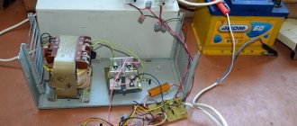
Sooner or later, every car enthusiast begins to need a battery charger. With the arrival of frost, I also thought about it. The batteries are old, they don’t hold a charge well, and I’m tired of borrowing chargers from friends. I drove around the city, looked at what was offered from a non-automatic one with the ability to adjust the charging current up to 10A. I looked at it, was stunned by the prices and decided, as usual, to conjure this device myself.
For implementation I chose a thyristor charger circuit. Simple, reliable, tested by a bunch of people. I am sure that devices assembled according to this scheme have already been in this community.