Device settings
Everyone knows that all car electronics are powered by 12V. In this case, the charging device must produce a current of 10% of the rated capacity. Without this, the memory will also work, but much slower.
To achieve these parameters, you will need:
- Transformer with 2 windings. The rule “the more turns, the better” applies here. If there are more windings, then it’s not scary. They just won't be used. Basically any pulse transformer will do.
- AC power comes from the outlet. A homemade car battery charger should provide a constant charger. In this case, you will need a rectifier.
- Tester. A multimeter is needed to determine the output voltage. It should be exactly 12 volts.
- It is impossible to make a battery charger without automatic control. Otherwise, the battery may explode. Therefore, a voltage control relay is necessary.
- Current adjustment will be required. A variable resistor will handle this. It is advisable to use a multi-turn current regulator so that the adjustment is smooth.
This is enough to assemble a simple charger.
The simplest scheme
The simplest circuit for assembling a charger for a car battery includes transformers. And what’s most interesting is that it is assembled from available components. But professional factory analogues are designed in a similar way. And, despite all the primitiveness of the homemade device, it is quite efficient.
In addition, such charging has a fairly high efficiency, and during operation it is not capable of generating heat. In addition, the device has a stable current, regardless of charge and supply fluctuations. In addition, there is short circuit protection.
Circuit diagram of a charger for a car battery
To assemble a homemade charger you need at least soldering skills, nothing more. Here are several circuit diagrams of a car battery charger that can be assembled in a couple of hours.
Simple circuits
Here are 3 circuit diagrams for a simple car battery charger. Perhaps you already have all the necessary components or you can buy them for next to nothing at a flea market.
With 1 diode
A 1 amp fuse and a switch are placed in front of the transformer for convenience. After the transformer, a diode is placed on one terminal of the winding, and a fuse on the other. You need to put an ammeter and a voltmeter in the gap. You can buy cheap Chinese testers with only a screen and wires. You can use Soviet switches.
The automatic charger circuit is not the best. The diode cuts off the lower part of the sine wave, which makes the pulsation uneven.
With diode bridge
This option is better suited for a car battery. DM is already a full-fledged voltage equalizer.
The charger for a car battery is assembled in the same way, but instead of a diode, a bridge is installed. From its minus, the wire goes to the fuse after the transformer.
You can buy a diode bridge or solder it yourself. To do this you only need 4 diodes. The diagram looks like this. The voltage is still pulsating, which is not good for batteries.
With diode bridge and capacitor
This is what a proper transformer charger looks like. A capacitor of 25-50 volts and 5000-6000 microfarads is placed between plus and minus.
The capacitor receives voltage and releases it, but already equalized and without ripple.
Adjustable circuits
If you want a homemade car battery charger to work correctly, you need a regulator. A regular tuning (variable) resistor of 4.7 kilo-ohms can handle this.
There are also 3 transistors in the circuit. Their location and number are signed, so there will be no problems. All you have to do is come to a radio store and show them the names. They are necessary for the resistor to work correctly.
Transistors need at least passive cooling, so it is better to attach an aluminum plate or install a cooler to their radiators.
Comment. In the diagram, an ammeter is installed in the gap of transistor P210 and the second fuse. With current and voltage adjustment, there is no need for it, since only the voltage needs to be adjusted. Therefore, it is better to put a voltmeter in its place.
A detailed video can be viewed below.
Reassembly of a switching power supply
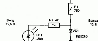
First, you should open the case, after which you should find that same TL431 chip. Now you need to pay attention to its output contact, near which there are two resistors (in the diagrams they are usually marked R12 and R13), connected by the REF leg.
It is optimal to adjust the upper arm of the divider. By reducing the resistance, the voltage at the output of the charger also decreases. If the parameter is increased, then the potential difference will also increase. If the power supply is designed for 12 V, then you will need a resistor with a higher resistance, and for 19 V - with a lower one.
Now, from a simple circuit of a charger for a car battery, you should remove the selected resistor (R13) and instead place a trimmer that is pre-set to the same resistance. After this, you need to apply a load to the charger output (for example, connect a light bulb from a headlight). Plug in and smoothly rotate the “trimmer” engine and at the same time control the voltage.
As soon as the required limits are reached (14.1-14.3 V), the power supply is disconnected from the network, and the “trimmer” engine is fixed in its position. Nail polish works well for this. Now all that remains is to assemble the body in reverse order. As a result, it doesn't take as much time as reading this entire manual.
The procedure for assembling a charger for a car battery
Consider how to make a charger for a car. This scheme is quite suitable for a beginner. It has been discussed previously. How to improve it is written above.
First you need to get a transformer. In radio equipment and old tape recorders you can find a good TS-180-2. It consists of 4 windings. It is necessary to connect pins 1 and 1 on the primary, and numbers 9 on the secondary. That is, if you connect 4 windings in 2 in series, you will get a two-winding transformer with a voltage of 13.6 volts, which is what is required for normal operation of the charger. You need to solder a power cord to pins No. 2.
How to connect a charger to a car battery? You just need to connect the diode bridge with wires with 10 pins. It is worth placing an ammeter with a limit of 15 amperes into the gap.
A voltage regulator is soldered into the ammeter circuit. You need to place a voltmeter between the terminals from the transformer.
To protect the automatic charger for car batteries, you need to install fuses. One on the battery side (10 A), the second at the input to the transformer (0.5 A).
You should not immediately set the current to high. To be on the safe side, you need to set the charger to a low current (from 1A), and then gradually increase it to 9-10A. When the battery is charged, the ammeter will show about 1 ampere. This means that the charger can be turned off.
Simple chargers with manual adjustment
Let's start with simple devices that allow you to manually adjust charging parameters. Since most passenger car batteries have a capacity of no more than 100-120 Ah, a charger that provides a current of up to 10 amperes will be quite sufficient.
Simple regulator with ballast capacitors
Anyone who knows how to use a multimeter and hold a soldering iron can make such a charger that does not have scarce parts. Let's take a look at the diagram below.
Circuit diagram of a simple charger with ballast capacitors
The device consists of a step-down transformer Tr1, a powerful rectifier assembled on diodes VD1-VD4 and a set of capacitors of different capacities C1-C4. Each of the capacitors can be connected to the transformer power circuit using a separate switch S2-S4. The capacitances of the capacitors are selected so that each subsequent one provides an output current of the charger twice as large as the previous one.
Depending on the rating and number of connected capacitors, the output voltage will change, and therefore the charging current. By combining capacitors with switches S2-S4, you can change the charging current from 1 to 15 A in 1 A increments, which is more than enough to charge any battery.
The voltage at the terminals of the battery connected to terminals XS2, XS3 can be monitored using a voltmeter PU1. The magnitude of the charging current will be shown by ammeter PA1. The power switch is toggle switch S1.
The design can use any network transformer (you can make it homemade) that provides a current of at least 10 A with an output voltage of 22-24 V. D305 diodes can be replaced with any rectifier designed for a forward current of at least 10 A and withstanding a reverse voltage of at least 40 V The rectifier bridge diodes must be installed on radiators isolated from each other with a dissipation area of at least 100 cm2 each.
Important! If semiconductors will be installed on one common radiator, then this must be done through insulating mica spacers. In this case, the dissipated area of the radiator is selected to be at least 300 cm2.
Capacitors C2-C4 are non-polar, paper, designed for an operating voltage of at least 300 V. Suitable, for example, are MBGCh, MBGO, KBG-MN, MBM, MBGP, which were widely used as phase-shifters for asynchronous motors in household appliances. Any DC voltmeter with a measurement limit of 30 V can work in place of PU1. PA1 is an ammeter with a measurement limit of 20-30 A, which can conveniently be used as any microammeter with an appropriate shunt.
With continuously adjustable charging current
The next circuit is more complicated, where it uses a thyristor as a regulating element. The advantage of this design is the smooth regulation of the output voltage, and therefore the charging current. The adjustment range is 0-10 A. The operating principle of the SZU is phase-pulse control of a key (thyristor).
The device consists of a power transformer T1, a rectifier bridge assembled on powerful diodes VD1-VD4, and a current control circuit assembled on transistors VT1, VT2 and thyristor VS1. An alternating voltage of 18-22 V is supplied from the secondary winding of the power transformer to the rectifier bridge. Straightened, it is fed to the control circuit. At the beginning of the half-wave, capacitor C2 begins to charge. Its charging speed can be smoothly adjusted using variable resistor R1.
As soon as the capacitor is charged to a certain value, an analogue of a unijunction transistor, assembled on elements VT1, VT2, will open. The capacitor will quickly discharge through the control electrode of the thyristor, the latter will open and will remain in this state until the end of this half-wave. When the next one appears, the process will repeat.
Expert opinion
Alexey Bartosh
Specialist in repair and maintenance of electrical equipment and industrial electronics.
Ask a Question
Thus, at each half-wave, the thyristor will open with one or another delay (depending on the charging time of capacitor C2), cutting off its leading edge. The larger part of the half-wave is cut off, the less effective voltage will be applied to the battery terminals, which means the charging current will be lower.
Any network transformer with a voltage on the secondary winding of 18-22 V at a current of at least 10 A is suitable as a power transformer. In place of VT1, in addition to the one indicated, KT361B-KT361E, KT502G, KT502V, KT3107A, KT501Zh-KT501K can work. Instead of KT315A, KT315B-D, KT3102A, KT312B, KT503V-G, P307 are suitable. Capacitors such as MBGP, K73-17, K42U-2, K73-16, K73-11 with a capacity of 0.47-1 μF can be used as C2. Instead of KD105B, KD105V, KD105G or D226 with any letter will do. Variable resistor R1 type SPO-1, SP-1, SPZ-30a.
Ammeter PA1 - any with a total deviation current of 10 A. Instead of powerful rectifier diodes D245, any of the KD213, KD203, D245, KD210, D242, D243 series, which can withstand a current of at least 10 A and a reverse voltage below 50 V, are suitable. They must be installed on radiators with an area of at least 100 cm2. Thyristor KU202V can be replaced with KU202G-E and even with T-160 or T-250. It is also installed on the radiator.
Healthy! If the output voltage of the transformer is slightly higher than 22 V (say, 24-28 V), then you can use it. The only thing is that it is necessary to increase the value of resistor R5 to 200 Ohms.
With asymmetric current charging
This charger has a current adjustment limit from 0 to 10 A and charges with an asymmetric current, in which the battery is charged for a certain time, and the rest is discharged with a current of about 600 mA. This significantly extends the life of the battery and prevents sulfation.
Here, the charging current is adjusted according to a high alternating voltage using a symmetrical thyristor (triac). The adjustment principle is the same as in the previous scheme - phase-pulse control. But the regulator circuit looks and works somewhat differently.
At the beginning of the positive half-wave, capacitor C2 is charged through resistor R3 and diode VD1 of the diode bridge VD1-VD4. As soon as the capacitor is charged to the ignition voltage of the gas-discharge lamp HL1 (charging time depends on the position of the variable resistor R1 slider), the latter will light up. The capacitor will quickly discharge through the control electrode of the triac, and it will open, supplying voltage to the mains winding of the step-down transformer T1.
The triac will remain in this state until the end of the half-cycle. With a negative half-wave, the capacitor will be charged through resistor R5 and diode VD2. In this case, the voltage polarity will be opposite to the previous one. Again there is a discharge in the lamp, the thyristor opens, passing a negative half-wave to the winding.
Expert opinion
Alexey Bartosh
Specialist in repair and maintenance of electrical equipment and industrial electronics.
Ask a Question
Curious! Resistors R3 and R5 play another important role. They alternately bypass the mains winding of the transformer through diodes VD3 and VD4. This prevents the triac from closing immediately after a short opening pulse until the current in winding T1, which is an inductive load, is higher than the holding current of the symmetrical thyristor.
The reduced voltage, the value of which depends on the position of the R1 slider, is rectified by diodes VD5, VD6 and supplied to the terminals of the battery, charging it with the current we have chosen. After the triac is closed and until it is opened again, the battery is discharged through the load resistor R6, which provides a discharge current of about 600 mA.
The charging current can be controlled using ammeter PA1; device PV1 shows the voltage at the battery terminals.
Important! When setting the value of the charging current using an ammeter, it is necessary to take into account the current (600 mA) flowing through resistor R6. That is, if we set 6 A on the device, the actual charging current flowing through the battery will be 6 – 0.6 = 5.4 A.
About the details. Any transformer of appropriate power (output current of at least 10 A) with an output voltage of 20 V and a tap from the middle is suitable as a network transformer. If the secondary winding does not have a tap from the middle, then you can use a rectifier assembled using a bridge circuit. Diodes VD5, VD6 - any powerful rectifier with a current of at least 10 A and a reverse voltage of at least 40 V.
VD1-VD4 can be replaced with any rectifier that can withstand a current of at least 200 mA and a voltage of 300 V. Capacitors C1, C2 - film or paper, non-polar. The triac can be replaced with KU208V. Ammeter PA1 has a measurement limit of 15-20 A, voltmeter PV1 - 20 V. Powerful rectifier diodes VD5, VD6 and triac VS1 must be installed on radiators. In this case, the diodes can be installed on a common radiator without insulating gaskets. Diodes VD1-VD4 do not need a radiator.
Automatic charging from power supply
A homemade recharger can also be made from a power supply from a computer. You'll have to modify it a little, but you get a good, almost factory memory. Perhaps the power supply can be found in the bins.
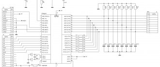
For the most part, power supplies are built on the basis of the TL494 PWM module. It is ideal for car chargers.
Next you just need to follow the instructions:
- All wires except yellow and black need to be cut.
- We solder them together: yellow with yellow, black with black.
- On the controller you need to cut the tracks that go to pins: 1, 14, 15, 16.
- It is necessary to make 2 holes in the case for trimming resistors (10 and 4.4 kilo-ohms).
- All that remains is to assemble this circuit. There is no need to route the board; everything is done by surface mounting.
In a do-it-yourself automatic charger, a multimeter that needs to be embedded into the PSU body will not hurt.
A simple pulse charger circuit
If you don’t want to search for a transformer or remake it, then you can pay attention to another option. If you have an unnecessary laptop charger lying around the house, you obviously shouldn’t throw it away, since this is a good option for creating a switching power supply for a battery.
Since the output voltage should not exceed 14.1-14.3 V, any ready-made unit is not suitable for this. However, you can start remaking it.
As a rule, in such devices, stabilizing power is maintained by a circuit that includes the following elements:
- TL431 chip;
- control optocoupler.
As soon as the output voltage exceeds the permissible limits (this is set by resistors), the microcircuit lights up the optocoupler LED. Thus, the PWM controller receives a signal about the need to reduce the duty cycle of the pulses that are supplied to the transformer.
At first glance, everything seems complicated, and it’s not really clear how to make a simple charger. At the same time, the manufacture of such a device is within the capabilities of every home craftsman with a personal car.
Safety precautions
When making a homemade charger, do not forget about basic safety rules:
- All devices, without exception, must be located on a fire-resistant surface, including the battery.
- The initial use of charging should be carried out with full control of all parameters. It is necessary to ensure control over the heating temperature of all elements of the charger and battery. Boiling of the electrolyte should be avoided; voltage and current must be controlled with a tester. All this will allow you to determine the duration of the battery to be fully charged, which will help in the future.
Assembling a charger for a car battery yourself using a simple circuit is not a problem. The main thing is to follow safety precautions. After all, you have to deal with dangerous voltage of 220 V!
Unnecessary block of a desktop computer
In this case, the “manufacturing” of a battery charger is difficult. However, this option for assembling a charger with your own hands does not require deep knowledge of electronics. In addition, the basis is already there - an old unnecessary power supply from a desktop computer, which is still operational.
Typically they provide an output voltage of +5 V and +12 V with a current of about 2 A. These parameters are quite sufficient to assemble a low-power device that will faithfully serve the owner of the vehicle for many years.
Fully charging the battery will require a certain amount of time, and quite a lot. Mainly it all depends on the capacity of the battery. However, using such a homemade device will avoid the effect of plate desulfation.
