What is grounding in a private house?
Grounding is the connection of metal network elements, equipment or mechanisms with a grounding device (ground loop), due to which, when leakage currents occur (insulation breakdown), the entire potential is completely transferred to the ground.
If we consider this issue at the “user” level, then grounding protects you from electric shock if the insulation in the electrical wiring is damaged.
How to connect zero and ground in an electrical panel and in what cases is this necessary?
How to correctly connect neutral and ground in the electrical panel of a private house or apartment.
Why do you need to connect the neutral wire to ground? What does the PUE say? When designing the power supply of buildings and structures, which include both working and protective grounding, the likelihood of voltage dangerous to the life and health of people appearing on the conductive (metal) housings of devices and equipment must be minimized. In this article we will talk about how to connect zero and ground and why it is needed. For those who are not interested in the preface and theory, the practical implementation is described at the end of the article. Content:
- Types of protection against electric shock
- Grounding systems
- Differences between grounding and grounding
- How to properly connect zero to ground
Is grounding necessary in a private house?
The danger of a short circuit is not only that household appliances and lighting fixtures fail. Grounding in a private house is necessary so that residents do not suffer from electric shock. This is possible if the wires are shorted to the device body. Electricity always seeks a way out and rushes into the ground. In nature, lightning, the same current, is always discharged upon contact with the ground. But if a person touches a bare conductor, his body itself becomes a conductor - the same earth. Often the outcome is extremely sad. Death occurs very often.
Is grounding necessary in a private house? Necessarily. The essence of the system is to provide the electrical charge with the shortest path for discharge into the ground. According to the laws of physics, he will look for a conductor with minimal resistance. And the circuit that will be discussed below is exactly this. And even if the “dose” is so large that the ground electrode cannot remove it completely, only a small part will pass through the human body and will not cause harm. Unless, perhaps, you will feel a slight short-term trembling. This shows that proper grounding is a guarantee of electrical safety.
According to GOST, SNiP and PUE, every residential building is required to be equipped with such a protection system against short circuits and stray currents. The regulatory documents, in particular, state that grounding for a home is installed if the design voltage in the power supply circuit with an alternating current of 100 V exceeds 40 W. Another problem that can be solved with the help of a grounding electrode is ensuring fire safety. As a result of short circuits, a fire often occurs, then a fire, and then the cost of restoration (if possible) is disproportionately greater than the cost of installing a ground loop.
How to properly make grounding in a private home is also asked by those who are faced with the problem of a bad signal. If there is a powerful emitter nearby, interference when using a telephone, TV, computer, or radio is inevitable. But if you protect the building, the received signal will always be excellent. But just don’t confuse this system with a lightning rod. In the latter case, the intended purpose is the same - the removal of a lightning discharge. In the event of a short circuit, the lightning rod will not be able to protect people from injury or devices from burning out. However, the general principle of operation is identical in both cases.
During installation, under no circumstances should the circuits of the lightning rod in the house be connected to grounding. Each system operates independently. Then, in the event of a lightning strike, there will be no power surge. If an induction effect occurs, the ground electrode will “remove” the current from the circuit, thereby ensuring safety. Moreover, each security system has an underground part. It can be general only if there is a sufficient cross-section. The wiring is always separate. The presence of one means of protection does not exclude the need to install another.
Protective circuit – generally accepted norm
The need to create a protective circuit is specified in PUE, SNiP and GOST. They are the very legally significant documents that regulate the activities of electricians and the actions of ordinary citizens when working with a 220 and 380 W power grid. It is these documents that will tell you how to make grounding in a private house, how to do it correctly. The advice of experts who will reveal all the secrets of mastery will also come in handy.
Previously, different standards were in effect. Two wires in electrical wiring was the generally accepted norm, but today such a network cannot be created. Everything has changed in accordance with the development of civilization and it is necessary to take care of the safety of your home yourself and pay attention to the electrical network.
Grounding standards
The main requirement for a grounding device is its resistance.
With a supply voltage in the system of 380/220V, this resistance for a private home should be no more than 30 Ohms.
If you have a gas boiler connected to your house, in order to protect and prevent a possible explosion of the boiler, gas workers impose more stringent standards - no more than 10 Ohms.
The lower the resistance of the grounding device, the greater its reliability.
According to Ohm's law I=U/R. That is, the less R, the greater the short-circuit current, which means the protective device will definitely work. But there are also “pitfalls” here, we’ll talk about them a little further.
Rules and requirements of the PUE
At any residential property located within the city limits and beyond, in accordance with the requirements of the PUE, special protection against dangerous voltages of 220/380 Volts is organized. For this purpose, special steel structures called grounding devices (GD) are installed on their territory. Their main purpose is to create conditions that guarantee the protection of people living in the house from electric shock.
In accordance with the PUE, chapter 1.7., part 1, clause 1.7.72, the dimensions of metal blanks are selected taking into account the need to obtain the required resistance to the flow of current into the ground. For various structural elements, these indicators may vary from sample to sample. However, their minimum sizes must comply with the following standards:
- the connecting strip between the pins cannot have a standard size of less than 12x4 mm (section 48 mm2);
- the pins themselves based on the corners are selected with sides of 4x4 mm;
- when using a round reinforcing bar, the cross-section should not be less than 10 mm2;
- the metal pipe should have a wall thickness of about 3.5 mm.
Please note: Having the owner of the house with data on the operating characteristics of the electrical circuit, in particular, will protect animals and residents from electric shock.
When arranging it, it is necessary to act in accordance with the provisions of industry standards regarding the operation of the equipment available at the site.
Basic requirements for ground loop resistance
If you do not know how to properly make grounding in a private house and what technical characteristics it should have, we recommend that you familiarize yourself with the PUE in which Chapter 1.7. entitled “Grounding and protective electrical safety measures” regulates the main technical characteristics of the grounding loop for equipment up to 1000 V.
According to this regulatory document, the resistance of the ground loop should be :
- No more than 4 Ohms for electrical installations up to 1000 V (this class of electrical installations includes the electrical equipment of a country house, house or cottage).
- No more than 10 Ohms if the total power of generators or transformers is less than 100 kVA.
- No more than 0.5 Ohm for electrical installations above 1000 V with large ground fault currents (over 500 A).
- No more than 10 Ohms for electrical installations over 1000 V with low ground fault current.
Differences in grounding and grounding
Do-it-yourself 380V grounding in a private house, the circuit of which assumes use in other conditions, is very different from grounding. Zeroing is often used in manufacturing plants. Grounding can only protect against short circuits and does not remove excess electricity. In domestic conditions, such a function is useless. It can even lead to burnout of electrical appliances.
Difference between grounding and grounding
Helpful information! When installing a grounding device, it is worth using a mechanism to turn off the equipment or a voltage limiter.
Types of ground loops
To quickly “drain” the current into the ground, the external subsystem redistributes it to several electrodes located in a certain order to increase the dissipation area. There are 2 main types of circuit connections.
Triangle - closed circuit
In this case, current is drained using three pins. They are rigidly connected by iron strips, which become the edges of an isosceles triangle. Before grounding a house in this way, it is necessary to understand the geometric proportions. The following rules apply:
- The number of pins and stripes is three.
- The pins are mounted in the corners of the triangle.
- The length of each strip is equal to the length of the rod.
- The minimum depth of the entire structure is about.5 m.
The structure is assembled before grounding is installed on the surface. The most reliable connection is a welded one. The tire is made from a strip of sufficient cross-section.
Linear
This option is made up of several electrodes arranged in a line or in a semicircle. An open contour is used in cases where the area of the site does not allow the formation of a closed geometric figure. The distance between the pins is selected within 1-1.5 depth. The disadvantage of this method is the increase in the number of electrodes.
Grounding schemes, which one to choose
Before making grounding in your private home, you will need to familiarize yourself with the features of the arrangement and operation of protective systems that involve the use of one of the well-known schemes. To do this, you need to consider the following important points:
- When organizing the power supply of any modern facility, in addition to the neutral and phase buses, a so-called “grounding” conductor must be connected to it.
- Its main purpose is to protect people from dangerous potential that enters the body of devices when the insulation of conductors is broken.
- To do this, the grounding bus on the substation side is connected to a special grounding element (circuit), which is installed directly on its territory.
Additional information: Thanks to this, the protection function via the neutral core (combined with the working zero or via a separate conductor) is transferred to the consumer side.
At the same time, the grounding devices considered here in the house are usually classified as “repeated” chargers, duplicating station ones in case of a break in the neutral (combined PEN conductor).
According to the method of grounding the neutral core of the transformer at the substation and the facility on the consumer side, all used circuits are divided into the following two categories:
- Firstly, these are systems with a solidly grounded neutral, which are the most common method of grounding transformers whose secondary windings are connected by a star. In this case, their midpoint is permanently connected to the circuit.
- Secondly, circuits with the so-called “isolated” neutral are often used, in which the middle point is not connected to ground or is connected to it through the high resistance of the protection device.
a) a network with a solidly grounded neutral, b) a network with an isolated neutral connected to the ground through an arrester
Useful note: In the second case, the working windings of the transformer perform a separating function and are usually used for industrial purposes or in special electric heating installations.
Their use is associated with the need to isolate current-carrying parts of equipment from the ground loop. According to the rules of electrical installations, a solidly grounded neutral is usually designated as “TN”. One of the most common methods of protective use of such a neutral is to connect metal housings of devices to it via a separate bus.
Why is grounding necessary?
Grounding in an electrical network is based on elementary physical laws and is a universal system for protecting people from electric shock, as well as a system for protecting electrical equipment for any purpose from insulation breakdown (grounding). Operation of electrical networks without grounding is potentially fire hazardous. Equipping a private home with a grounding loop is a prerequisite for the safe use of any electrical appliances and devices.
According to the rules for the construction of electrical installations (hereinafter referred to as PUE), which apply to all types of electrical installations, protective grounding must be provided.
1.7.56. To prevent electric shock if the insulation is damaged, the following protective measures in case of indirect contact should be applied separately or in combination:
- protective grounding (1.7.63, 1.7.65, 1.7.66);
— automatic power off (1.7.61, 1.7.63);
— potential equalization (1.7.78);
- equipment of class II or with equivalent insulation (1.7.86, 1.7.87);
— protective electrical separation of circuits (1.7.86, 1.7.88);
— insulating (non-conductive) rooms, zones, areas (1.7.86, 1.7.89);
— ultra-low (low) voltage systems BSNN, ZSNN, FSNN (1.7.68–1.7.70);
— potential equalization (1.7.65, 1.7.66).
For an objective understanding, you need to understand the following terms, according to the PUE:
- Direct touch is electrical contact of people or animals with live parts that are energized, or approaching them at a dangerous distance.
- Indirect touch is electrical contact of people or animals with an exposed conductive part that becomes energized as a result of insulation failure.
- Protection against direct contact - protection that prevents electric shock in the absence of damage to the insulation of conductors.
- Indirect contact protection - protection that prevents electric shock in the event of a single fault.
- Ground electrode - a conductive part (conductor) or a set of interconnected conductive parts (conductors) that are in electrical contact with the ground directly or through an intermediate conductive medium, such as concrete.
- Grounding conductor is a conductor connecting the ground electrode to a specific point in the system or electrical installation or equipment.
- Grounding device - a set of electrically connected grounding conductors and grounding conductors, including elements of their connection.
Grounding - making an electrical connection between a specific point in a system or installation or equipment and the local ground.
Note. Connection to local ground may be intentional, unintentional, or accidental, and may be permanent or temporary.
Having convinced yourself of the need for grounding, you can begin to consider the issue of independently equipping a private house with a grounding loop.
Grounding calculation for a private house: formulas and examples
Electrical installation rules (PUE) and GOST establish the exact framework for how many ohms the grounding should be. For 220 V it is 8 ohms, for 380 it is 4 ohms. But do not forget that for the overall result, the resistance of the soil in which the grounding loop is installed is also taken into account. This information can be found in the table.
| Type of soil | Maximum resistance, Ohm | Minimum resistance, Ohm |
| Alumina | 65 | 55 |
| Humus | 55 | 45 |
| Loess deposits | 25 | 15 |
| Sandstone, groundwater depth deeper than 5 m | 1000 | – |
| Sandstone, groundwater no deeper than 5 m | 500 | – |
| Sandy clay soil | 160 | 140 |
| Loam | 65 | 55 |
| peat bog | 25 | 15 |
| Chernozem | 55 | 45 |
Knowing the data, you can use the formula:
Formula for calculating rod resistance
Where:
- Ro – rod resistance, Ohm;
- L – electrode length, m;
- d – electrode diameter, m;
- T – distance from the middle of the electrode to the surface, m;
- Req – soil resistance, Ohm;
- T – distance from the top of the rod to the surface, m;
- ln – distance between pins, m.
But this formula is difficult to use. For simplicity, we suggest using an online calculator, in which you only need to enter data in the appropriate fields and click the calculate button. This will eliminate the possibility of errors in calculations.
To calculate the number of pins we use the formula
Formula for calculating the number of rods in a contour
where Rn is the standardized resistance for the grounding device, and ψ is the climatic coefficient of soil resistance. In Russia they take it as 1.7.
Let's consider an example of grounding for a private house located on black soil. If the circuit is made of a steel pipe, 160 cm long and 32 cm in diameter. Substituting the data in the formula, we get no = 25.63 x 1.7/4 = 10.89 . Rounding the result up, we get the required number of grounding conductors – 11.
Differences in grounding for 220V and 380V networks
The differences in the grounding systems of private houses with an operating voltage of 220 V or 380 V are insignificant. In both cases, a grounding loop is constructed. The difference lies in the way the circuit is connected to the home electrical network.
In a 220V network, the voltage is single-phase. In this case, a three-wire conductor and sockets with three contacts (phase, neutral, grounding) are used.
For 220 V network
The network is 380 V - three-phase voltage. In this case, a five-wire conductor and sockets with five contacts are used (phase - 3 pcs., neutral, ground electrode).
For 380 V network
DIY grounding device: step-by-step instructions
If you are asking the question: “how to make grounding at the dacha?”, then to complete this process you will need the following tool:
- a welding machine or inverter for welding rolled metal and bringing the circuit to the foundation of the building;
- an angle grinder (grinder) for cutting metal into specified pieces;
- wrenches for bolts with M12 or M14 nuts;
- bayonet and pick-up shovels for digging and burying trenches;
- a sledgehammer for driving electrodes into the ground;
- a hammer drill for breaking up rocks that may be encountered when digging trenches.
In order to correctly and in accordance with regulatory requirements perform a grounding loop in a private house, we will need the following materials:
- Corner 50x50x5 - 9 m (3 segments of 3 meters each).
- Strip steel 40x4 (metal thickness 4 mm and product width 40 mm) - 12 m in the case of one grounding point connected to the foundation of the building. If you want to make a grounding loop along the entire foundation, add the total perimeter of the building to the specified amount and also take a reserve for trimming.
- Bolt M12 (M14) with 2 washers and 2 nuts.
- Copper ground electrode. A grounding conductor of a 3-core cable or a PV-3 wire with a cross-section of 6–10 mm² can be used.
Once all the necessary materials and tools are available, you can proceed directly to the installation work, which is described in detail in the following chapters.
Choosing a place for installation
When choosing a site in the local area suitable for arranging a protective contour, we proceed from the following considerations:
- it should not be located too far from the house; this will not only save on the connecting bus due to its short length, but also reduce the resistance of the current flow circuit;
- the soil at the site where the control panel is installed must be soft enough to allow metal pins to be driven into it;
- The quality of the soil on the site also affects the effectiveness of grounding (loams, plastic clay and peat have minimal resistance).
Important! If suitable soil layers are deep, the length of the corner pins will have to be increased to reach the desired soil layers.
Ground loop material
The grounding loop consists of vertical and horizontal grounding conductors. Material from which it is not recommended to make vertical grounding conductors:
- ⚡corrugated fittings
- ⚡round steel with a diameter of less than 10mm
What can be made from:
- ⚡round steel 14mm or more (with a smaller diameter it is difficult to drive an electrode into the ground)
- ⚡steel corner with dimensions of at least 40*40*5
The end of the angle or round steel is cut at an angle of 30 degrees. This is the most optimal angle for steel to enter the ground.
The horizontal grounding conductor is made from a steel strip 40*4.
Pin parameters and materials
Electrodes or pins are usually made of steel profile. This material is attractive due to the possibility of deepening the rods by simply driving it in. At the same time, its electrical resistance fully satisfies the requirements with a sufficient cross section. Pins can be made from the following materials:
- Bar. The most common option is a rod with a diameter of 16-18 mm. It is not recommended to use fittings, because it is heated, which leads to an increase in resistivity. In addition, the corrugated surface leads to irrational use of the rod cross-section.
- Corner. The most commonly used corner is 50x50 mm in size with a wall thickness of 4-5 mm. The bottom is pointed to make driving easier.
- Pipe with a diameter of more than 50 mm with a wall thickness of 4-5 mm. Thick-walled pipes are recommended for hard soils and regions with frequent droughts. Holes are drilled at the bottom of such a pin. When the soil dries out, salt water is poured into the pipe, which increases the dispersive ability of the soil.
In what cases is it necessary to check the ground loop?
If you are installing a grounding device in a private house or country house, then the test can be performed with a regular test light (as described above), but if you need to put the facility into operation, legalize a change in the power supply scheme, or enter into a power supply agreement with a specialized organization , then you will need a ground loop test report.
This document can only be issued by a certified laboratory that will take measurements. In this case, the contractor that installed the grounding loop is obliged to provide you with a passport for the grounding loop with certificates for hidden work.
Why is a ground loop necessary?
Grounding in a private house can be done with your own hands. This method will remove stray currents and prevent the accumulation of static electricity on electrical equipment.
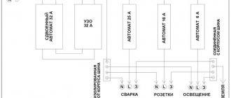
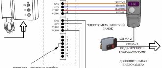
Installation diagram to the ground terminal in the panel
Related article:
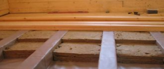
Electrical wiring in a wooden house: step-by-step instructions. With minimal knowledge of electrical work and with the help of our guide, you can do the wiring in your home yourself.
The circuit protects residents from electric shock. If the zero phase is broken, the housing of electrical equipment poses a great danger. For such cases, a grounding loop is provided, which is the phase through which electricity goes into the ground.
How does a lightning rod circuit work?
Helpful information! The device helps reduce the risk of fires and overloads, and also increases safety when working with various equipment.
Features of 220 and 380 V grounding schemes
The connection in each case is special. The only thing that remains unchanged is the outer contour. The design can be any (closed, linear). But from the moment you enter the house, you need to take into account some nuances. The same applies to the wiring device. A voltage of 220 Volts requires a two-wire line. In this case, one will have to be split into “ground” and “neutral”. The other is mounted on insulators.
380V is a power supply that uses a four-wire system. One of the cores must be split, as in the previous case. The rest are mounted through insulators without contacting each other. Another feature of this installation method is the need to use additional protective equipment. These are RCDs and differential circuit breakers. A “neutral” conductor is connected to them.
Choosing a grounding scheme for a private house
Today, there are two protection schemes against the damaging effects of current - TN-CS and TT connections. The peculiarity of the first is that in the neutral wire the protective zero is combined with the working one, while the second has a solidly grounded neutral. The supply of electricity to a private home most often occurs using overhead lines with a TN-C grounding scheme, which are characterized by the presence of a phase conductor (L) and a protective conductor PEN combined with neutral. To connect your own earth circuit, two methods are used:
- conversion of traditional circuit to TN-CS;
- connection to ground using the TT system.
Looking ahead, we note that the TT connection has become more widespread, since it involves grounding all current-carrying parts of the equipment. Nevertheless, let's consider both of these methods.
TN-CS connection
It has already been repeatedly stated above that a separate protective wire is not provided in the TN-C system. To obtain a connection point to grounding, the combined PEN conductor is divided into two separate lines - protective (PE) and zero working (N).
When connecting TN-CS, the PEN wire is divided into two separate lines
For these purposes, an insulated N busbar is installed in the electrical panel; in addition, a PE busbar is installed, connected to the cabinet casing. The PEN wire from the power line is connected to the latter. As busbars, pieces of copper tape are used, the cross-section of which corresponds to the maximum current strength. Then a jumper is installed between the two buses, and the shield itself is connected to the ground loop. The phase wire is mounted on a separate insulated busbar.
TT connection
This type of protection does not require any separation of the PEN wire. As in the previous case, the phase wire is attached to a separate insulated busbar, and the PEN conductor combined with the working neutral is connected to another busbar isolated from the panel. In the future, it is considered an ordinary neutral wire. The ground loop is connected to the metal casing of the cabinet, so it is not connected to the PEN wire.
Grounding connected according to the TT scheme involves isolation of the N and PE lines
Thanks to the features of this connection, there are advantages in comparison with the TN-CS circuit:
- if the PEN conductor combined with the working neutral burns out, the housing of any consumer will not be energized (the potential will be zero);
- the lack of connection between the network neutral and the protective wire makes it impossible for a phase imbalance voltage to appear on the electrical equipment housing.
Skeptics may claim that the cases described above will trigger the residual current device (RCD), which is equipped with almost all protective systems today. However, you shouldn’t tempt fate and rely on electronics - it’s better to provide yourself with double protection. It should be noted that due to the need for additional voltage relays and RCDs, the TT system costs consumers more than the TN-CS, so when choosing it, you must be prepared for additional expenses.
Video: TN-CS and TT grounding systems
Grounding of individual household appliances and equipment
It often happens that owners of private houses (especially country houses) do not see the point in installing full grounding. We cannot justify or condemn anyone, which means it is also worth considering this option. Let's figure out how to ground a water heater in a private house without installing the entire protection system.
Grounding sign GOST-21130
This is quite easy to do using a natural grounding electrode. From it you need to lay a cable directly to the device or to the outlet from which the device is powered. Often, a gas boiler in a private home is grounded in this way, but any other household appliance can be protected in this way.
There are “electricians” who, when asked how to ground an outlet in a private house, advise throwing a jumper from the neutral contact to the grounding one. It is clearly not worth listening to such advice - it is fraught with problems. We will definitely talk about such errors today. And now it’s worth taking a closer look at how to check a finished grounding loop to see if it meets the necessary requirements.
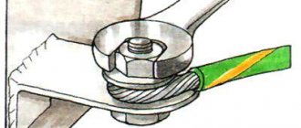
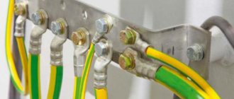
The connection seams on the tires must be well welded
Ready-made grounding kits for a private home
Self-installation can significantly reduce the cost of the grounding system. However, ready-made kits allow you to speed up work and increase the reliability of the circuit. The following models can be distinguished:
- ZandZ is a circuit with one or more stainless steel electrodes. Allowed depth is up to 10 m. The price depends on the length of the pins. The average price of a set with five-meter electrodes is 23,500 rubles.
- Galmar - has electrodes up to 30 m long. The average price is 41,000 rubles.
- Elmast . This system is manufactured in Russia and adapted to Russian operating conditions. Price – from 8000 rubles.
Important! There are many models on the Russian market, which allows you to make the best choice. The driving depth of their electrodes ranges from 5 to 40 m. The price range is 6,000-28,000 rubles.
Common mistakes when performing installation work
There are a number of characteristic shortcomings that people who are not specialists are susceptible to. If you know them, you can avoid possible mistakes. The list includes:
- Treatment of electrodes with moisture protection. Some people simply paint them, not realizing that the paint layer eliminates conductivity. Electricity is not released, the system does not perform its intended function.
- Refusal to weld. The welding machine is expensive, you don’t want to pay rent, and there is a misconception that the connection pins can be connected with bolts. Such fasteners will retain electrical conductivity for no more than one to two weeks. Corrosion will cause failure.
- Attempts to “move” the external contour as far as possible from the residential building. As a result, throughput decreases as the total resistance of the system increases. This occurs because the input is too large and becomes an obstacle to the movement of electrons.
- Saving on profile and wires. An insufficient section will work until the first case. Then the wires or other elements simply burn out, and it’s good if the grounding gets the job done until then. Next time, the harmful consequences of the short circuit are inevitable.
- Applications of copper and aluminum. Again, such a solution is resorted to in the name of economy. Often there are veins in the garage, workshop, or storage room. But when connecting such conductors, welding is impossible, which means that corrosion will eventually damage the circuit.
As soon as there is reason to think that there is a problem and the grounding is not working, find out what the problem is. Eliminate it immediately. Only in this case can the safety of property and health of family members be guaranteed. Hoping that the threat will not arise is perhaps the biggest mistake. This is why fires happen in private homes, people suffer, and household appliances break down.