Grounding for home
The article will touch upon the issue of installing grounding in a private home, country house, or small production facility with your own hands.
Many people mistakenly believe that grounding is an unnecessary, additional thing that, out of harm, is required by the energy supply organization or inspection inspectors. The most important thing that any consumer of electricity should understand is that grounding is an integral part of any power supply. This is the same necessity as installing automatic switches in the switchboard, metering devices and other equipment. To perform grounding efficiently, it is necessary to carry out a large amount of excavation work. Roughly calculate that, at a minimum, you will have to manually dig one cubic meter of earth. You will also need a welding machine and welding skills.
The best option is to do the grounding yourself, since not all electricians like to do it, and those who do, for the most part, do it poorly.
So, how is a ground loop made correctly?
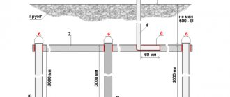
There are two most common options for a ground loop - a triangle and a linear one, in the form of a continuous strip along the house.
Both are correct. Which one to choose is up to you to decide, based on the free space near the house.
triangle ground loop linear ground loop
DIY grounding device: step-by-step instructions
If you are asking the question: “how to make grounding at the dacha?”, then to complete this process you will need the following tool:
- a welding machine or inverter for welding rolled metal and bringing the circuit to the foundation of the building;
- an angle grinder (grinder) for cutting metal into specified pieces;
- wrenches for bolts with M12 or M14 nuts;
- bayonet and pick-up shovels for digging and burying trenches;
- a sledgehammer for driving electrodes into the ground;
- a hammer drill for breaking up rocks that may be encountered when digging trenches.
In order to correctly and in accordance with regulatory requirements perform a grounding loop in a private house, we will need the following materials:
- Corner 50x50x5 - 9 m (3 segments of 3 meters each).
- Strip steel 40x4 (metal thickness 4 mm and product width 40 mm) - 12 m in the case of one grounding point connected to the foundation of the building. If you want to make a grounding loop along the entire foundation, add the total perimeter of the building to the specified amount and also take a reserve for trimming.
- Bolt M12 (M14) with 2 washers and 2 nuts.
- Copper ground electrode. A grounding conductor of a 3-core cable or a PV-3 wire with a cross-section of 6–10 mm² can be used.
Once all the necessary materials and tools are available, you can proceed directly to the installation work, which is described in detail in the following chapters.
Selecting a location for installing the ground loop
In most cases, it is recommended to install the ground loop at a distance of 1 m from the foundation of the building in a place where it will be hidden from the human eye and which will be difficult to reach for both people and animals.
Such measures are necessary so that if the insulation in the electrical wiring is damaged, the potential will flow to the ground loop and a step voltage may arise, which can lead to electrical injury.
Excavation work
After a location has been chosen, markings have been made (for a triangle with sides of 3 m), and the location for the strip with bolts to be laid out on the foundation of the building has been determined, you can begin excavation work.
To do this, it is necessary to remove a 30–50 cm layer of earth around the perimeter of a marked triangle with sides of 3 m using a bayonet shovel. This is necessary in order to later weld the strip metal to the ground electrodes without any special difficulties.
It is also worth additionally digging a trench of the same depth to bring the strip to the building and bring it to the facade.
Hammering of grounding conductors
After preparing the trench, you can begin installing the ground loop electrodes. To do this, you must first sharpen the edges of a 50x50x5 corner or round steel with a diameter of 16 (18) mm² using a grinder.
Next, place them at the vertices of the resulting triangle and, using a sledgehammer, hammer them into the ground to a depth of 3 m
It is also important that the upper parts of the grounding conductors (electrodes) are at the level of the dug trench so that a strip can be welded to them
Welding work
After the electrodes are driven to the required depth using a 40x4 mm steel strip, it is necessary to weld the grounding conductors together and bring this strip to the foundation of the building where the grounding conductor of the house, cottage or cottage will be connected.
Where the strip will reach the foundation at a height of 0.3–1 moth of earth, it is necessary to weld an M12 (M14) bolt to which the grounding of the house will be connected in the future.
backfilling
After all welding work has been completed, the resulting trench can be backfilled. However, before this, it is recommended to fill the trench with saline solution in the proportion of 2-3 packs of salt per bucket of water.
Afterwards, the resulting soil must be compacted well.
Checking the ground loop
After completing all the installation work, the question arises: “how to check the grounding in a private house?” Of course, a regular multimeter will not be suitable for these purposes, since it has a very large error.
To perform this activity, the F4103-M1 devices, Fluke 1630, 1620 ER clamps, and so on are suitable.
However, these devices are very expensive, and if you do the grounding at your dacha with your own hands, then to check the circuit, an ordinary 150-200 W light bulb will be enough for you. For this test, you need to connect one terminal of the lamp socket to the phase wire (usually brown) and the second to the ground loop.
If the light bulb shines brightly, everything is fine and the grounding circuit is fully functioning, but if the light bulb shines dimly or does not emit a luminous flux at all, then the circuit is mounted incorrectly and you need to either check the welded joints or install additional electrodes (which happens when the electrical conductivity of the soil is low).
Types of ground loops
There are several types of structures used for grounding.
Traditional grounding systems
A system of this type consists of a minimum number of elements: two vertical electrodes made of metal reinforcement and one horizontal in the form of a strip, which connects the two previous ones. The sections and dimensions of the elements must comply with the standards. It is recommended to install grounding on the northern shaded side of the site, in a damp place. However, due to the fact that the contour is often made of steel and cannot be coated with paint, it quickly corrodes. Also, the resistance of such a device is affected by the temperature and moisture level of the soil, since the circuit is placed in the upper layers.
Deep grounding systems
Such a system is manufactured using a modular-pin method. Compared to the previous version, it differs:
- long service life;
- simple calculations;
- non-exposure to environmental influences;
- no need for maintenance;
- ease of installation.
Resistance measurements of mounted equipment should be carried out by specialists.
The external grounding loop consists of vertical electrodes and horizontal grounding elements. It is made of four strips 40-50 mm thick and installed at a distance of at least 1 m from the building. The horizontal strip should be located at a depth of 50 to 70 cm from the surface.
Ground loop
The design of the grounding loop and the types of materials used are limited by the conditions contained in the documents, for example, in the PUE, the rules for electrical installations.
All electrical installations, without exception, must be grounded, both at the substation and at the enterprise or at home.
The most common design of a ground loop is one or more metal pins (ground electrodes) buried in the ground and welded together. Using a metal conductor, the ground loop is connected to the grounded devices.
Ground loop
Unpainted steel or copper-coated steel materials are used as grounding conductors, the dimensions of which should not be less than those given below:
- Round rolled products – diameter not less than 12 mm;
- Corner – at least 50x50x4 mm;
- Pipes – with a diameter of at least 25 mm and a wall thickness of at least 4 mm.
The better the conductivity of the grounding electrodes, the more efficiently the grounding works, so the most preferable option is to use copper electrodes, but in practice this does not occur due to the high cost of copper.
Uncoated steel has a high corrosion ability, especially at the interface between moist soil and air, so the minimum thickness of the metal walls is determined (4 mm).
Galvanized metal resists corrosion well, but not in the case of current flow. Even the most minimal current will cause an electrochemical process, as a result of which a thin layer of zinc will last a minimum time.
Modern grounding systems are based on copper-plated steel. Since the amount of copper for production is low, the cost of the finished materials is not much higher than steel, and the service life increases many times over.
Ground electrode from the corner
The most common ground loop designs are triangular or row electrode placement. The distance between adjacent electrodes should be 1.2-2 m, and the laying depth should be 2-3 m. The laying depth (electrode length) largely depends on the characteristics of the soil. The higher its electrical resistance, the deeper the electrodes should lie. In any case, this depth must exceed the freezing depth of the soil, since frozen soil has a high ohmic resistance. The same applies to areas of land with low humidity.
Where high currents may flow, for example, in a substation or an enterprise with powerful equipment, the approach to choosing the design of the ground loop and its calculation are of great importance for safety.
Dimensions and distances for ground electrodes
Mandatory conditions that must be observed when installing grounding in a private house:
- ⚡the length of the electrode that is driven into the ground. It should be at least 2.5-3 meters
Initially, it is better to take an electrode 3 m long. Since in the process of hammering it with a sledgehammer, the part that is hit will be flattened. In the end, you will have to cut off a few centimeters of such a flattened electrode with a grinder.
- ⚡distance between electrodes. It should also be 2.5-3 meters
Regardless of what type of contour you have - in the form of a triangle or a straight line. This is due to the phenomenon of current spreading from grounding conductors. If the electrodes are hammered closer than 2.5 m, then it turns out that it makes no difference how many electrodes you hammered in.
They will work almost like one electrode.
- ⚡ deepening of the trench from the planning mark of the ground - 0.7-0.8 m
The trench is a place to lay the strip connecting the electrodes. With less deepening of the trench, the strip will be exposed to precipitation and a rapid corrosion process. With greater depth, the risk of exposure to dampness from groundwater again arises.
- ⚡the distance of the grounding loop from the foundation of the house is at least 1 m
- ⚡after excavating the trench, it is sprinkled with sand for better drainage of water from the horizontal ground electrode.
Clutchless rods
By the way, despite all the advantages and good contact, many consider threaded connections to be the weakest point of such modular systems.
Think about water pipes lying in the ground. After several years of operation, it is the threaded couplings that rust first.
The same thing can happen with pins. In addition, at the moment of hammering with a vibrating hammer, the connection often weakens. Simply put, the thread is unscrewed.
Experienced installers, after each entry of another rod into the ground, tighten the electrode along the thread. At this point another mistake occurs.
When you tighten a smooth pin or socket with a serrated wrench, you scratch and strip the copper layer from the surface. What this leads to was discussed above.
After 3-4 years, instead of a full-fledged electrode, you will be left with a hollow copper tube with rusty dust inside.
This way you will not touch either the electrode or the coupling.
Also note that in all coupling kits, the coupling itself is slightly wider than the diameter of the rod. What does this mean? A narrower electrode, when entering the ground following such a coupling, will not be in close enough contact with the soil surface
To obtain real resistance indicators, sometimes you have to wait several days until the earth crumbles and compacts all the free spaces
A narrower electrode, when entering the ground following such a coupling, will not be in close enough contact with the soil surface. To obtain real resistance indicators, sometimes you have to wait several days until the earth crumbles and compacts all the free spaces.
Therefore, many people prefer a different type of deep grounding rods. For example, like OBO Bettermann with the BP (Bundes Post) system.
In such sets, the pins are joined together without threads, using the pressing method.
This is something like a tongue-and-groove connection with a self-release pin. When driven in, the tenon is tightly wedged into the groove and an absolutely monolithic connection is obtained.
Sometimes inside the hole at the end of one rod there may be a lead ball, which, when struck, fills the entire space even more tightly.
Therefore, if you do not trust couplings and want to eliminate the human factor, buy such kits.
Grounding device. Types and features. Rules and installation
Most of the houses in our country are equipped with a power transmission system that does not have grounding, according to the old model. It must be remembered that the operation of modern household devices without a grounding loop contributes to the occurrence of various malfunctions in their operation, and, as a result, failure. House owners have to make their own grounding device, which is necessary to create electrical safety.
The main task of grounding is to disconnect the network voltage when a current leak occurs. This can be expressed in the form of a person touching live parts, damage to the insulation of electrical wires. Another, no less important function of grounding is to create normal conditions for the operation of household electrical devices.
Some devices require, in addition to a grounding contact in the socket, a direct connection to the grounding bus. There are special clamps for this.
For example, a microwave oven can create a background that is dangerous to humans if it is not connected directly to the ground bus. There may be a special grounding terminal on the back wall of the oven body. And if you touch a washing machine without grounding with wet hands, your hands may sting unpleasantly. This problem can only be solved by connecting the ground to the body of the washing machine. With an electric oven, the situation is similar to previous cases.
Principle of operation and purpose of grounding
Most of the suburban sector receives power from a 220 volt AC network. The electrical circuit exists due to two conductors - phase and neutral. Electrical appliances are equipped with protective devices and insulation that help prevent voltage from reaching the metal parts of their housings. However, the possibility of voltage appearing there cannot be ruled out, since the insulating layer is sometimes penetrated by current, and the elements of the devices fail.
Once on the housing, electricity poses a threat to the life and health of a person who touches the surface of the device. It is especially dangerous if objects that act as natural grounding conductors (metal pipes, structural elements of a building, etc.) are located near the current source. When the ground electrodes touch, the circuit opens and the current is directed towards the lowest potential, that is, into the person.
To understand the principle of grounding and its importance, knowledge within a school physics course is sufficient. One of the physical properties of current is that it always finds the conductor with the least resistance
Thus, to ensure human safety, it is necessary to create a highway in which the resistance will be significantly less than in the human body.
The average resistance of the human body is 1000 ohms (although this value varies significantly depending on the circumstances). There are complex calculations of the resistance value required for grounding, according to which the optimal value is 30 Ohms (for household electrical appliances). If we are talking about lightning protection of a private home, the preferred value is 10 Ohms.
Grounding tasks:
- Guaranteed drainage of voltage from conductive objects to the ground.
- Equalizing the potentials of all objects located in the country house.
- Creating conditions for the proper operation of all electrical safety systems, including circuit breakers, residual current devices and fuses.
- Avoiding situations where static charges accumulate on the housings of electrical appliances.
- Maintaining electrical equipment in good condition. For example, the operation of switching power supplies on computer equipment often involves applying voltage to system units. As a result of the discharge, electronic components break down and information is lost.
Large household appliances must be protected by a grounding system:
- The boiler is made of stainless steel, which reacts negatively to stray currents removed by grounding. When a stray current appears, a person is in serious danger: a shock is possible while taking a shower or simply touching the boiler.
- Washing machine. The device is characterized by high electrical capacity, which occurs due to high humidity in the room.
- Computer. The power supply is designed in such a way that the operating leakage in this element is even higher than that of the washing machine.
- Electric stove. This type of household appliance is characterized by high power, which results in an increased risk of breakdown.
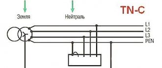
Grounding system TN-CS
This scheme involves combining two conductors at a certain stage before entering a residential building:
- Working zero supplied from the transformer substation
- Protective grounding conductor.
For this purpose, you need to install a distribution board outside the house in which to place two busbars connected to each other by a jumper. Both conductors are connected to one of them, and one wire goes out - PE; wire N goes out from the second. Thus, the circuits are connected and split into working and grounding.
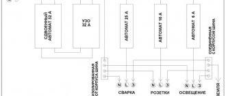
Three wires enter the shield inside the house:
- one – L phase;
- second – N zero;
- the third is a PE conductor.
Each socket is connected with a grounding circuit, providing grounding for all electrical appliances that have a Euro plug.
Grounding scheme according to the TN-CS system with PE conductor
Practical advice: despite the presence of grounding, to provide more complete protection against electric shock, an EPS device is recommended.
Issues covered in the PUE
Regulation of the operating procedure for various types of protective systems can be presented in the form of a certain set of requirements relating to the arrangement of individual structures.
According to them, the functional readiness of grounding loops, which include a whole set of structural elements, must be confirmed by the following technical data:
- Description of the design and composition of protective devices used in existing electrical installations;
- Formulas for calculating their sizes, as well as the resistance standards of grounding devices (GD);
- Tables with correction factors that allow you to introduce corrections for the quality and condition of the soil at the location of the contour (taking into account the material of individual elements);
- The procedure for organizing and conducting control tests available for grounding systems.
On a note. The presence of documented data on the performance characteristics and reliability of the functioning of the grounding loop of a private house, for example, will eliminate the possibility of electric shock to animals and residents.
When installing it, you are required to act in strict accordance with the PUE, as well as comply with all requirements regarding the operation of this protective device.
Selecting a system and drawing up a diagram
There are three grounding systems in total: TT , IT , TN , of which the latter is divided into three more varieties - TN-S , TN-C , TN-CS .
In private housing construction, TN-CS or TT system designs are usually used, and TN-CS looks more attractive since there are fewer requirements for its installation.
The system starts from the main grounding bus, which is installed either in the electrical panel of the house or in the input device cabinet.
The most rational solution is when the grounding is located on a support that redirects the electric main into the house.
The TT system is used much less frequently. This is handled by representatives of the energy supply organization, and if the owner still decides to save money and carry out the installation himself, then the same Energosnab employees will come to certify the documents.
If you still take a chance and choose a CT grounding scheme for a private house, then do not forget about the mandatory installation of an RCD!
Grounding quality
It was already mentioned above that the type of soil and material for the system affect the quality of the ground loop. But besides this there are several more positions.
Ground area
Let's say right away that the larger the grounding area, the higher its quality. Therefore, when the question is what to use: a grounding rod or a plate, the second option is chosen. Why? It's all about its larger area. The contact area of the grounding plate is several times larger than that of the pin. In this case, this area can, in principle, be increased indefinitely. And this is a big plus. For this purpose, “PTCE” plates made of a nickel-copper alloy are usually used.
Therefore, most often, when it is planned to ground high-voltage lines, for example, 10 kV overhead line supports, the plate version (PTCE) is used. Although the area indicator can be increased in another way. You can simply use a grounding rod, not just one, but several, tying them around the supports of a 10 kV overhead line with a loop of good conductor. That is why in private housing construction a circuit of three or four pins is used. For a 10 kV overhead line, the quantity can be increased indefinitely. For production facilities it is not necessary to use a square or triangle; a linear structure can be used here. The main thing is to install more rods on the line.
The larger the grounding area, the higher its quality
There is another option to increase the contact area with the ground. This is to increase the size of the pins. That is, make them longer and thicker. By the way, this option is used if the upper layers of the soil have high resistance, and the lower ones, on the contrary, have low resistance. Such deep grounding works great even if one metal pin is installed. True, for 10 kV lines the number of grounding conductors will have to be increased; one alone will not solve anything here. But it is better to install PTCE.
Grounding calculation
We will not dwell on this section for long. The thing is that calculating grounding is not easy. There is a fairly large and complex formula by which the calculation is made. But, as practice has shown, its final result is just an inaccurate figure. Why? Because it all depends on the type of soil. Our land in many areas is a layer cake made from different fillings. Therefore, it is possible to determine exactly where and what layer is located only using a special geological exploration map.
That is why, when choosing deep grounding, it is necessary to focus on the maximum indicator, substituting different values of soil resistance into the formula.
Installing a ground loop
There are several installation methods. The new, but more expensive method of modular-pin installation is good for everyone. But we will look at this method a little later. We will analyze the classic installation of a ground loop.
First, preparatory work is carried out.
Preparation for installation
We decide on the installation location of the protection. The best solution would be to locate the circuit close to the building and on the side where the electrical distribution panel is installed.
Based on the requirements of paragraph 1.7.111 of the PUE, all vertically and horizontally located electrodes must be made of copper, galvanized or ordinary steel angle or other profile. The surface of grounding conductors must not be painted for better current dissipation and detection of defects.
For arrangement, we will need 50 corners of shelves with a thickness of 5 mm and a strip with a width of 40 mm. These are the main materials for making the circuit itself. We will also need wires of sufficient cross-section to construct an internal grounding loop and separate the wiring into a neutral wire and a ground conductor.
Now we prepare the shovel for work and begin the main stage of work.
Installation of the protective device
We dig a triangular trench - a side length of 3 m, the width of a shovel bayonet and a depth of at least half a meter. You can make a straight trench - at least 6 m long (devices have been equipped in this way recently). If we use the old method, we use a sledgehammer to hammer the grounding rods into the corners of the equilateral triangle to the required depth. It cannot be inserted into a finished well; it must sink tightly and without gaps at a depth of no more than 3 m.
When equipping a straight-line system, every meter, we hammer in 1 ground electrode, but no more than 5 pieces. For better penetration into the ground, sharpen the edges of the corner on a sharpening machine or cut them with a grinder. The stakes should not be completely immersed in the ground; there should be a section of the corner at least 200 mm above the ground surface.
We put on a welding suit and mask, prepare the apparatus and weld horizontal electrodes from a strip of at least 40 mm wide to the vertical grounding conductors. From it, to the wall of the building, along the dug trench we draw a strip or section of power cable of sufficient cross-section. Now, we bring it into the building and connect it to the incoming electrical panel, and from it we ground the in-house system.
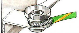
When conducting a grounding conductor using a power cable, work is performed in the following way: onto a vertical grounding conductor, using a bolt and nut with a reliable clamp, we secure a piece of cable packed into the end contact. To complete this work you will need:
- copper bus whose cross-section is more than 10 mm2;
- aluminum, with a cross section of more than 16 mm2;
- metal conductor with a cross-section of more than 75 mm2.
After checking the quality of the seam, we cover all welding points with a primer or melted resin. At the welding site, the metal is weakened due to the high temperature during welding and is more susceptible to corrosion. Having completed all the final work, we fill the trench. First, add a layer of sand, and then fill it with excavated soil.
All the main work has been completed, now all we have to do is measure the resistance of the ground loop.
Do-it-yourself grounding schemes for private houses: 380 V and 220 V
When installing grounding loops, there is no significant difference between the 3-phase (380 volt) and single-phase (220 volt) circuit of a private house. But it is present in the cable routing. Let's figure out what it is.
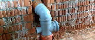
Proper entry into the house. This is how it should look ideally
With a single-phase network, a three-core cable (phase, neutral and ground) is used to power electrical appliances. A three-phase network requires a five-core electrical wire (the same ground and neutral, but three phases)
Particular attention should be paid to the connection - the grounding should not come into contact with zero
Let's consider the situation. 4 wires (zero and 3 phases) come from the substation, connected to the distribution board. Having arranged the correct grounding on the site, we insert it into the shield and “plant” it on a separate bus. The phase and neutral conductors pass through the entire automatic device (RCD), after which they go to electrical appliances. From the grounding bus, the conductor goes directly to sockets and equipment. If the zero contact is grounded, the residual current devices will trip for no reason, and such installation of electrical wiring in the house is completely useless.
The do-it-yourself grounding scheme at the dacha is not complicated, but it requires a careful and careful approach when performing it. It’s easy to do it for only one boiler or other electrical appliance. We will definitely dwell on this below.
The body of a gas boiler, like metal pipes, requires high-quality grounding to avoid sparks.
What is a ground loop in a private house: definition and design
A grounding loop is a structure of pins and busbars located in the ground that provides current drainage if necessary. However, not any soil is suitable for installing a ground electrode. Peat, loam or clay soil are considered suitable for this, but stone or rock are not suitable.
The circuit is ready. All that remains is to lay the tire to the wall of the house
The grounding loop is located at a distance of 1÷10 m from the building. To do this, dig a trench ending in a triangle. The optimal dimensions are side lengths of 3 m. Electrode pins are driven into the corners of the equilateral triangle and connected by a steel bar or angle by welding. From the top of the triangle the tire goes to the house. We will look at the algorithm of actions in detail in the step-by-step instructions below.
Having figured out what the grounding loop is, you can move on to calculating the material and dimensions.
Grounding calculation for a private house: formulas and examples
Electrical installation rules (PUE) and GOST establish the exact framework for how many ohms the grounding should be. For 220 V it is 8 ohms, for 380 it is 4 ohms. But do not forget that for the overall result, the resistance of the soil in which the grounding loop is installed is also taken into account. This information can be found in the table.
| Type of soil | Maximum resistance, Ohm | Minimum resistance, Ohm |
| Alumina | 65 | 55 |
| Humus | 55 | 45 |
| Loess deposits | 25 | 15 |
| Sandstone, groundwater depth deeper than 5 m | 1000 | – |
| Sandstone, groundwater no deeper than 5 m | 500 | – |
| Sandy clay soil | 160 | 140 |
| Loam | 65 | 55 |
| peat bog | 25 | 15 |
| Chernozem | 55 | 45 |
Knowing the data, you can use the formula:
Formula for calculating rod resistance
Where:
- Ro – rod resistance, Ohm;
- L – electrode length, m;
- d – electrode diameter, m;
- T – distance from the middle of the electrode to the surface, m;
- Req – soil resistance, Ohm;
- T – distance from the top of the rod to the surface, m;
- ln – distance between pins, m.
But this formula is difficult to use. For simplicity, we suggest using an online calculator, in which you only need to enter data in the appropriate fields and click the calculate button. This will eliminate the possibility of errors in calculations.
To calculate the number of pins we use the formula
Formula for calculating the number of rods in a contour
where Rn is the standardized resistance for the grounding device, and ψ is the climatic coefficient of soil resistance. In Russia they take it as 1.7.
Let's consider an example of grounding for a private house located on black soil. If the circuit is made of a steel pipe, 160 cm long and 32 cm in diameter. Substituting the data in the formula, we get no = 25.63 x 1.7/4 = 10.89. Rounding the result up, we get the required number of grounding conductors – 11.