How to make light music with your own hands? Throw a New Year's party and amaze your friends with amazing musical colored lights that light up and change color to the beat of the music. These lights are nothing more than simple RGB LED strips connected to the electronic brain - the Arduino controller.
You can install LED strips anywhere in the house or even outside. You can use color music not only during parties, but also when listening to music every day. Glue LED strips to the TV, to the sofa, to the table or walls - wherever you want. The only condition is that there must be a sound source nearby: an audio signal that will be fed to a color music unit (CMU) and processed by the device.
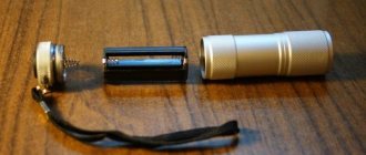
As already mentioned, an Arduino controller is used to receive an audio signal, process it and output it through digital outputs to LED strips. A 12 V power supply is used to power the Arduino board and LED strips. The device has an audio input and output connector. From the input connector, the signal goes to the Arduino controller and the output jack for connecting headphones or speakers to it. The project can be completed in two hours (maximum three) using readily available components. You will be very surprised to see the final result of the project (photos do not convey all its beauty).
Here is a short video of home color music in action:
youtube please provide the correct link
Let's start implementing color music on Arduino!
Complex circuits
They will allow you to create more professional schemes from the user's point of view.
First version of the scheme
It is assembled on five diodes. All of them are five millimeter and 3 V, have clear lenses. The transistor used is KT815 or KT972. Its task is to strengthen and act as a key. Everything is done like this:
- Power is supplied from 2 1.5-volt batteries;
- There are respectively two inputs for music: X1 and X2;
- In place of LED3 we install a red diode, the remaining remaining pairs will be blue and green;
Note. As a result, we get a very successful color and music scheme. The LEDs glow very effectively to the beat of the music, the circuit consumes little current, and low frequencies are reproduced simply superb. You just need to be careful: the LEDs may not be able to withstand loud music and burn out.
Second version of the scheme
We find the KT817 transistor, wires, headphone plug and SD tape. Started:
- We solder the transistor according to the following scheme;
- Then the CD tape is added and everything is moved to the luggage compartment of the car.
What is needed to make color music
To create such an installation, you can only use fixed resistors, the power of which is 0.25-0.125. To find out the resistance value, look at the strips located on the base.
The circuit also includes R3 resistors and trimmed R. The main condition is the ability to install them on the board on which the installation is being made. If we talk about capacitors, then when working, we take products whose operating voltage is at least 16 volts (any type is suitable). If finding capacitors C7 is problematic, then parallel connection of a pair of smaller capacitances is allowed, then you will get the necessary values. The capacitors C6, as well as C1, used in the variant under study must be started at 10 volts, and the rest at 25. In the case when outdated Soviet parts need to be replaced with imported ones, it is necessary to understand that they are all designated differently. Therefore, take care in advance to determine the polarity of the elements that will be mounted. Otherwise, the circuit may fail.
Also, to create color music with your own hands, you will need a diode bridge, the operating current of which is 200 milliamps and the voltage is 50V. In a situation where installing a finished bridge is not possible, it can be created using rectifier diodes. For convenience, they can be removed from the board and mounted separately, using a smaller workspace.
To create one channel you will need 6 LEDs of all colors. If we talk about transistors, then VT2 and VT1 are quite suitable; here the index does not play a special role.
Competition for beginner radio amateurs “My amateur radio design”
Competition design for a beginner radio amateur “Five-channel LED color music”
Hello dear friends and site guests!
I present to your attention the third competition work (second competition of the site) of a novice radio amateur.
Author of the design: Morozas Igor Anatolyevich
:
Five-channel LED color music
Hello radio amateurs!
Like many beginners, the main problem was where to start, what my first product would be. Started with what I wanted to purchase a home first. The first is color music, the second is a high-quality headphone amplifier. I started from the first one. Color music using thyristors seems to be a hackneyed option, so I decided to put together color music for LED RGB strips. I present you with my first job.
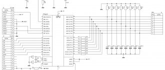
The color music scheme was taken from the Internet. Color music is simple, with 5 channels (one channel is white background). You can connect an LED strip to each channel, but for it to work at the input you need a low-power signal amplifier. The author suggests using an amplifier from computer speakers. I went from a complicated point, to assemble an amplifier circuit according to the datasheet on a TDA2005 2x10 W microcircuit. This power seems to me to be enough, even with a reserve. I diligently redraw all the diagrams in the sPLAN 7.0 program
Fig. 1 Color music circuit with an input signal amplifier.
In the color music circuit, all capacitors are electrolytic, with a voltage of 16-25v. Where it is necessary to observe polarity, there is a “+” sign; in other cases, changing the polarity does not affect the blinking of the LEDs. At least I didn't notice it. KT819 transistors can be replaced with KT815. Resistors with a power of 0.25 W.
In the amplifier circuit, the microcircuit must be placed on a radiator of at least 100 cm2. Electrolytic capacitors with voltage 16-25v. Film capacitors C8, C9, C12, voltage 63v. Resistors R6, R7 with a power of 1 W, the rest 0.25 W. Variable resistor R0 - double, with a resistance of 10-50 kohms.
I took a factory switching power supply with a power of 100W, 2x12v, 7A
On a day off, as expected, a trip to the radio market to purchase radio parts. The next task is to draw a printed circuit board. For this I chose the Sprint-Layout 6.0 program. It is recommended by radio specialists for beginners. It is easy to study, I am convinced of this.
Fig 2. Color music board.
Fig 3. Power amplifier board.
The boards were manufactured using LUT technology. There is a lot of information about this technology on the Internet. I like it when it looks factory, so LUT did the parts too.
Fig 3.4 Assembling radio components on a board
Fig 5. Checking functionality after assembly
As always, the most “difficult” thing when assembling a radio circuit is to assemble everything into a housing. I bought the case ready-made at a radio store.
I made the front panel this way. In the Photoshop program, I drew the appearance of the front panel where variable resistors, a switch and LEDs should be installed, one from each channel. The finished drawing was printed with an inkjet printer on thin glossy photo paper.
I glue photo paper onto a degreased prepared panel with holes using wood glue:
Then I place the panels under the so-called press. For a day. As a press, I have a 15 kg barbell plate:
Final assembly:
Here's what happened:
Attachments to the article:
(2.9 MiB, 2,909 hits)
Dear friends and site guests!
Don’t forget to express your opinion on the competition entries and take part in voting for your favorite design on the site’s forum. Thank you.
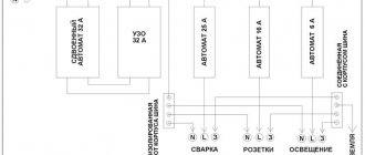
Some suggestions for those who will repeat the design: 1. You can connect speakers to such a powerful stereo amplifier, then you get two devices in one - color music and a high-quality low-frequency amplifier. 2. Even if the polarity of connecting electrolytic capacitors in a color music circuit does not affect its operation, it is probably better to observe the polarity. 3. At the color music input, it is probably better to install an input node for summing signals from the left and right channels (). According to the author, judging by the diagram, the high-frequency color music channel (blue) is supplied with a signal from the right channel of the amplifier, and the remaining color music channels are supplied with a signal from the left channel of the amplifier, but it is probably better to supply a signal to all channels from the audio signal adder. 4. Replacing the KT819 transistor with KT815 implies a reduction in the number of possible LED connections.
Homemade color music
Homemade color music in the interior of your own car will be of interest to all lovers of beautiful disco music. Making it with your own hands is absolutely easy. Color music at home can be quickly and easily assembled if you know some of the nuances of the circuit and its correct installation.
Color music from LEDs
An original scheme for making beautiful color music. In this case, you need a housing made of plexiglass. Let's get started:
- We select two plates measuring 5x15 cm and two square plates 5x5 cm;
- A couple of holes are made in one of the parts (for power supply and headphones);
- We mat and sand all the plates;
- We find LEDs that we also matte for a better effect;
- We assemble the body using a heat gun, which is ideal for working with plexiglass;
- Now we assemble the electrical circuit for color music according to this diagram:
- We connect the wire from the headphones with the corresponding connector to the car radio and enjoy the effect.
The plexiglass case can be installed in the car interior, anywhere. Everything will depend on individual preferences, wire length, etc. During the work process, the following must be taken into account:
- The output voltage of the adapter and the rated voltage of each diode must be interconnected. In other words, the total number of diodes involved in the circuit must equal the ratio of the adapter's output voltage.
Note. As an example, if the adapter is 12V, and the voltage for each diode is 3V, then the total number of LEDs should be 4.
- It is advisable to use a 3-core wire, one of the wires of which should be left unused.
Circuit with signal from speaker
Another popular scheme for creating color music. We do the following:
- We take the signal from the speakers (see).
Note. In this case, it is very important not to short-circuit the output of the SPD*. For this purpose, we solder only one wire.
UZP* — Sound card amplifier
- Arranges the switch so that it turns on the LEDs based on music;
- We select the resistance according to the diagram below, where the rating for turning on one diode is indicated;
Note. If the color music will be assembled from 4 LEDs, then the R value should be equal to 820 Ohms.
Popular multi-color scheme
Another common scheme involves the possibility of increasing nutrition. This will be especially true if a chain of many LEDs is used. The scheme is like this:
- There should be two frequency filters. They allow HF and LF to pass through at the input;
- The signal then goes to the amplifier stages, and then to the LEDs;
- It is recommended to connect inputs 1 and 2 to the source speaker.
Advice. If you want to make color music brighter, then you just need to reduce the resistor values to a couple of hundred, and change the transistors to KT817.
This scheme has one advantage that no other has: the ability to use LEDs of any color. So, when playing low-frequency bass, the red LED will blink, while playing midrange and high-frequency – green. As for setting the brightness, it is regulated by the sound volume rotary: the higher the sound, the brighter the glow.
Thyristors in color music
Until now, the article has only talked about color and music devices using LEDs. If there is a need to assemble a digital control unit using incandescent lamps, then thyristors will need to be used to control the brightness of the lamps. What is a thyristor anyway? This is a three-electrode semiconductor device, which accordingly has an anode
,
Cathode
and
Control electrode
.
KU202 Thyristor
The figure above shows the Soviet thyristor KU202. Thyristors, if you plan to use them with a powerful load, also need to be mounted on a heat sink (radiator). As we see in the figure, the thyristor has a thread with a nut and is attached similarly to powerful diodes. Modern imported ones are simply equipped with a flange with a hole.
One of these thyristor circuits is shown above. This is a three-channel color music circuit with a step-up transformer at the input. When selecting analogue thyristors, you should look at the maximum permissible voltage of the thyristors, in our case for the KU202N it is 400 volts.
The figure shows a similar color music circuit to the one shown above, the main difference in the lower circuit is that there is no diode bridge. Also, LED color music can be built into the system unit. I assembled such a three-channel color music with a preamplifier in a casing from a cider. In this case, the signal was taken from the computer’s sound card using a signal divider, the outputs of which connected active acoustics and color music. It is possible to adjust the signal level, both overall and separately by channel. The preamplifier and color music were powered from a 12 Volt Molex connector (yellow and black wires). The preamplifier and three-channel color music circuits for which they were assembled are shown above. There are other LED color music schemes, for example this one, also three-channel:
Color music on 3 LEDs - diagram
In this circuit, unlike the one I assembled, inductance is used in the mid-frequency channel. For those who want to first assemble something simpler, here is the following diagram for 2 channels:
If you collect color music using lamps, you will have to use light filters, which in turn can be either homemade or purchased. The figure below shows the filters that are commercially available:
Some fans of color and musical effects assemble devices based on microcontrollers. Below is a diagram of four-channel color music on the AVR tiny 15 MK:
The Tiny 15 microcontroller in this circuit can be replaced with tiny 13V, tiny 25V. And at the end of the review, I would like to say on my own that color music using lamps is inferior in terms of entertainment to color music using LEDs, since lamps are more inertial than LEDs. And for self-repetition, I can recommend this one:
We all want a holiday from time to time. Sometimes you want to be sad or experience other emotions. The easiest and most effective way to achieve the desired result is to listen to music. But music alone is often not enough - visualization of the sound flow and special effects are needed. In other words, we need color music (or light music as it is sometimes called). But where can you get it if such equipment in specialized stores is not cheap? Do it yourself, of course. All you need for this is a computer (or a separate power supply), several meters of LED RGB strip with a power consumption of 12V, a USB development board (AVR-USB-MEGA16 - perhaps the cheapest and simplest option), as well as a circuit diagram for , what and where to connect.