Antenna options
All types of radio antennas can be divided into mobile and stationary, they can also be directional and non-directional.
Directional ones are characterized by orientation to a specific point (signal source) in space; they operate over short distances (50-100 m). Omnidirectional are focused on the signal over the entire surrounding area.
The antenna can also be rod, wire or telescopic. The latter is a folding structure reminiscent of a multi-legged fishing rod. Such models are often found on tape recorders, stereo systems, and cars.
Whatever the type of antenna, the principle of operation of the devices is the same.
APRA classification
Antennas installed on a car are classified according to the following main characteristics:
- for its intended purpose, taking into account the further use of the received signal;
- according to the method of installing the antenna device;
- at the location of the receiving device;
- by the method of amplification of the received radio signal.
Appointment of APRA
By purpose they are distinguished:
- radio antennas that receive broadcast signals from radio stations exclusively for the car radio;
- TV antennas – for receiving television broadcasts;
- GPS antennas – for the car navigation system and traffic route correction;
- mobile radio antennas for radio communications.
Installation methods for automatic control gear
Based on the method of installing antenna devices on cars, they are distinguished (see figure below):
Methods for installing antenna devices
- magnetic AUGRA, equipped with magnetic soles for fixation on a metal surface (mainly on the roof);
- mortise antennas that require a hole in the body;
- antenna devices on an elastic suction cup, which ensures reliable adhesion of the device base to the car body;
- Automatic gearboxes using a threaded connection;
- radio antennas on clamps, also called gutter or overhead antennas, mounted on metal gutters;
- built-in devices, the main elements of which are hidden during installation under sealing rubber bands, in doors, etc.
APRA locations
Depending on the location on the car, there are two types of antenna devices:
- external (or external) antennas placed on the outside of the vehicle;
- internal (or cabin) antenna devices, most often fixed on the windshield inside the cabin.
The best result of receiving FM broadcasts is achieved if the AUGRA is placed outside in the center of the car roof as the highest point of the car. In this case, a good radio signal will be picked up from all directions.
Types of radio signal amplification
In accordance with the method of signal amplification, AUGRA are divided into:
- passive, without a built-in radio signal amplifier;
- active automatic control gear equipped with a built-in amplifier.
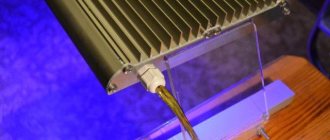
In Fig. Below is shown one of the modifications of the active external radio antenna of the famous Calearo brand, installed on the rear of the car roof.
Calearo active external control gear model
Features of radio wave propagation
Before turning to step-by-step instructions on how to make an antenna yourself, it is necessary to clarify the features of radio signal transmission in the VHF and FM bands. This will help you better understand the principle and design of the antenna.
Important to remember:
- reception of a high-quality signal is possible only within visibility (for example, when a television and radio tower is visible from the window of a house);
- capturing a signal at a great distance from the broadcasting object in the evening and at night is problematic;
- precipitation weakens or completely interrupts signal transmission.
Foil antenna
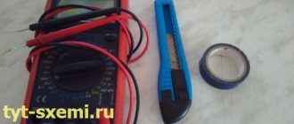
The manufacture of a signal-catching structure will require the following tools and materials from the craftsman:
- a coil of copper wire or foil;
- knife;
- pliers or wire cutters;
- dry board (square with a side of 15 cm).
If you look at the photo of antennas for FM radio made of wire or foil, it immediately becomes clear that there is nothing complicated in such a design.
First you need to cut a square out of foil (13 cm along the outer edge, the width of the foil strip is 1.5 cm). A small rectangle (3 mm) is cut out at the bottom center to open the frame.
How to choose a phase meter - review, purpose, principle of operation, scope of application + instructions for use with photosHow to make a transformer with your own hands - step-by-step instructions, diagram, drawings, list of materials + photo of a finished homemade transformer
Which hidden wiring detector is better? TOP 10 best manufacturers with photos and descriptions
The cut foil is glued to the board. With a shift to the right from the central slot by 2.5 mm and 2.5 cm apart from each other, the inner rod of the shielded wire (right) and the braid (left) are soldered to the square of foil.
If the device is planned to operate in the VHF range, then the square is increased to 15 cm, and the width of the foil strip should be 1.8 cm.Sometimes you can strengthen a weak radio signal by simply winding the antenna with a piece of copper wire. Its free end is brought out into the window. Such manipulation will not affect the sound quality in any way.
Homemade FM antenna
Greetings to readers and subscribers. In comments and letters, there are numerous requests to talk about how to make an FM antenna yourself and give an example of such a design with detailed instructions for making a simple FM antenna. In this regard, we publish this article. Three simple FM antenna designs are described here.
Making an FM antenna with your own hands using a design paired with a radio receiver increases the power of the radio signal at FM frequencies (88 - 108 MHz) by 60-100%. An increase in sensitivity and reception quality is achieved by vertically installing the antenna under the radio wave propagation range of the transmitting antennas. Let's consider the design of three simple antennas. Manufacturing time is from half an hour to three hours. The construction will require inexpensive or used materials.
FM antenna foil square.
Required materials and tools:
- Dried board, fiberboard, dielectric material.
- Metal foil.
- A piece of shielded cable with a resistance of 50-75 Ohms.
- Plug for connecting to a radio receiver.
- Soldering iron, flux, solder.
The manufacturing process of this FM patch antenna is not complicated and takes a minimum of time. A square frame is made from a single piece of foil with the dimensions indicated in the figure and a 15 mm wide cutout at the bottom of the frame. The finished frame is fixed with glue on a flat base made of wood, fiberboard, or any dielectric material. The central core of the coaxial cable is soldered to the bottom edge of the square, to the right or left of the cutout. In the figure, all dimensions are indicated in millimeters, there is no strict reference to sizes, the minimum acceptable size is indicated in brackets, the maximum without brackets. The distance between cable solders (braid and central core) varies from 25 to 40 mm. Designations: 1 – dielectric material; 2 – foil;
The considered design of a homemade FM antenna is installed indoors or outdoors. The signal is tuned by moving the antenna in the vertical direction and rotating it around its axis.
Tube FM antenna.
The antenna design is based on indoor water or heating pipes
Necessary materials:
- Ferrite core from a line transformer of an old tube TV.
- Glue, sticky, insulating tape.
- Brass or copper foil.
- Mounting copper wire 1.5 m with a cross section of 0.25 sq. mm.
- Connecting pins for connecting the antenna to the receiver.
To make the winding, insulating tape or paper is placed on the ferrite core in two layers. A single layer of foil, laid on top of the paper with a coil overlap of 1 cm, is insulated at the overlap area with electrical tape to prevent contact between the two sides of the coil. 25 turns of wire are wound onto the prepared screen with taps at 7, 12 and 25 turns. The resulting communication circuit is wrapped with a screen by analogy with step 1, followed by connecting the screens to each other. The ends of the wire are inserted into the connecting pins. The connection of the 7th turn pin with the screens is connected to the “grounding” socket of the radio receiver, the remaining pins are connected to the “Antenna” terminal. The reception setting is made by selecting the connections of the windings of the communication circuit.
Reliable grounding of such an FM antenna using in-house heating pipes allows you to receive transmissions during a thunderstorm without the risk of equipment damage. Vertical installation of pipes in a high-rise building increases the power of the radio signal by 1.5-2 times.
Omnidirectional FM antenna made of coaxial cable.
The antenna is used to amplify the radio signal in an area of poor reception.
Necessary materials:
- A piece of television cable of 1.5 m or more.
- Plastic tube 1.5 m long, 20 mm in diameter.
- Wooden mast.
At a distance of 750 mm from the beginning of the wire, an incision is made to further remove the plastic insulation and preserve the integrity of the screen braid. After kneading and loosening the braid, it is necessary, without damaging the copper core, to turn the screen towards the place where the insulation is cut. Having the screen on the opposite side of the central wire matches the characteristic impedance of the antenna. It is necessary to install and secure the antenna in any way inside a plastic tube with further attachment of the structure to a wooden mast. The signal is tuned after connecting the antenna to the receiver and adjusting the required height of the mast in the vertical direction.
Setting up the reception of such an omnidirectional homemade FM antenna is done without rotating the structure around its own axis. The use of a shielded cable in the circuit eliminates the influence of interference that occurs during the operation of household appliances on the quality of reception.
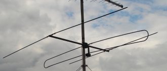
DIY rod antenna
If the foil solution does not give the desired effect, you can try making a highly directional antenna rod that resists city noise. Its design is more complicated than the previous version, but still within the power of a craftsman.
The diagram of a self-made FM antenna shows that the device consists of a conductor (metal rod or tube), which is attached to an insulator, and counterweights.
Technological maps in construction - what is it?- How to fix a laptop that won't charge
Insulated dielectric screwdrivers up to 1000V - tips on how to choose the best manufacturer
The length of the pin depends on what wavelength you plan to receive.
When the device is prepared, it must be mounted on the facade of the building. The end of the wire is inserted into the corresponding socket on the radio or music center (tape recorder). The final touch is to find radio transmitting stations.The principle applies here: the length of the pin is equal to a quarter of the wavelength. This is the best option; increasing and decreasing will affect the quality of radio broadcasting.
Whip antenna
The simplest DIY radio antenna is made literally from scrap materials. It is made in the form of a vertical pin from any material that conducts electric current. The lower end of the pin is connected to the input of the radio receiver and attached to the supporting surface through an insulator. The top one remains free.
The main requirement for a whip antenna is its length, which is equal to a quarter of the wavelength of the received signal. If it is intended to be used over the entire fm range, then the wavelength of the center of the range is taken for calculations.
And yet, it must be durable and withstand external influences without bending. But that's not the main thing. If you insert a piece of wire into the radio socket and fasten the free end to the surrounding piece of furniture closest to it, the reception will become better. This is the simplest analogue of a whip antenna.
Its second analogue is a telescopic rod built into the receiver. By changing its length, the central frequency of reception is adjusted, and by changing in space, the best quality is achieved for a given range: remember about polarization.
Coaxial cable to the rescue
A weak and poor-quality signal often becomes the reason for refusing to use the radio in such areas.
You can solve the problem using a coaxial cable. To work you will need:
- wooden slats;
- television cable (about one and a half meters);
- plastic tube (diameter 2 cm, length 1.5 m).
The process of creating a device is quite simple. First you need to make a cut on the insulating layer.
Dielectric insulated tool for work - which one is better to choose? Review of manufacturers, photos + video- Properties, scope of application of Paroc basalt insulation
- Mitsubishi Electric: company history
This must be done carefully, trying not to damage the braid. Then the exposed braid is slightly kneaded, and the foil screen is turned towards the incision site.
Antennas for receiving signals in the FM range can be purchased in specialized stores. The choice of models is quite large.At the last stage, you need to secure the prepared cable well inside the plastic tube and mount it on the rail. You need to move the homemade structure up and down in order to search for a wave; rotating around its axis will not bring results.
You can save a little and try to design the device yourself. Having even a little experience, using the right circuits, you can count on a good result - a homemade antenna will give high-quality and loud sound.
Full Size Broadcast Reception Vibrator
Find a good piece of cable in a field or forest; high-quality reception outside the city is important. What to do. Let's make a full-wave vibrator dipole with a resistance of 300 Ohms, a matching device of 75 Ohms:
- We remove the insulation of the RK-75 cable, 1.5 meters long, leaving the braid.
- Carefully pull the screen down another 1.5 meters. A metal tube will not be a suitable solution instead; try using foil or tape. You will need a DIY radio antenna for the duration of your hike. The main thing is that the screen segment extends for 1.5 meters.
- We make a matching device that is connected after the start of the “stocking” (in the middle of the vibrator). We cut off the antenna from the cable and get down to business.
- The U-elbow should be 1.5 meters long (half the wavelength), and at the central point it should be bent in half and tied with thread. The connection diagram looks like this:
- The stocking is placed on one end of the U-knee.
- At the start of the stocking, the insulation is cut through to the core. The core is simultaneously connected to the other end of the U-elbow and the output wire with a resistance of 75 Ohms.
- We ground the knee and output cable screens. But! Not our homemade antenna.
The vibrator itself is hung on a tree trunk facing the direction of broadcasting (the thickness of the wood introduces attenuation for catchers who choose the wrong orientation). A shish kebab skewer stuck under a tree is suitable for grounding. Hang the receiver nearby. The DIY radio antenna is wound up after use for use the next time.
Please note: the characteristic impedance of the matching device is equal to the impedance of the antenna. Ideal - 300 Ohm. The cable is in the store, but you’re unlikely to find it expensive (forest, mountains).
For a half-wave split vibrator (cut in the middle), the connection to the U-elbow of the output cable must be made three-quarters of the way, not to the very end. In the right place, the matching element is cut, touching the core, and the output cable RK-75 is connected. The U-elbow itself can be made using the indicated brands of coaxial.
The first design (previous subsection) seems simpler; it is not customary to use quarter-wave split vibrators. But an elbow can be made by dismembering the RK-50 cable (like the antenna). Skillful hands are an integral part of saving money. Think of the design process as paid work. Things will be more fun.
Photo tips on how to make an antenna for FM radio with your own hands
Did you like the article? Share

1+