For normal operation of electrical devices, periodic surgical intervention is necessary. Routine repair of the transformer is a prerequisite for its reliable operation in the future.
How often does transformer maintenance need to be performed? It is impossible to give a clear answer to this question, since the technical condition of two pieces of equipment with the same service life may differ. Current standards establish a maximum time interval - no less than once every four years.
1.4. Preventive and repair work.
Routine repairs of power transformers (without removing the core) with their shutdown are carried out depending on operating conditions in accordance with local instructions, but at least once a year.
Routine repair of transformers consists of cleaning insulators, covers; inspection of all contact connections, expander, exhaust pipe; checking gas protection, etc. The duration of repairs is usually no more than 6-8 hours.
Overhauls of power transformers with core removal are carried out 6 years after commissioning and thereafter as necessary, depending on the results of their measurements and inspections.
Major repairs are carried out with the removal of the core and are accompanied by an internal inspection of the transformer. During this repair, the magnetic circuit is carefully inspected, the tightening of the coupling bolts, windings, contact connections, insulation are checked, the tank and expander are cleaned; replace all gaskets; carry out all possible preventive tests in accordance with standards, etc. The period for overhaul of a transformer is determined by its power and ranges from 1 to 10 days.
During major repairs, as well as when installing new ones, transformers are tested in accordance with the “Scope and Standards for Testing Electrical Equipment”. In addition, preventative testing is carried out between major overhauls within the time limits established by local regulations.
During the tests, the insulation resistance of the windings, the dielectric loss tangent are measured and the absorption coefficient is determined. If the test results indicate that the insulation is wet, the transformer is dried. The insulation of accessible tie bolts and yokes is tested with an alternating voltage of 1 kV for 1 min. Violation of the insulation of these elements can cause serious consequences in operation, as it leads to the formation of a short-circuited circuit in the magnetic circuit and a “fire” of the steel.
Equipment for repair of power transformers from GlobeCore
GlobeCore company produces a wide range of equipment that can significantly facilitate routine and major repairs of power transformers.
From us you can purchase:
- installations for purification and regeneration of transformer oils;
- installations for topping up transformer oils;
- installations for vacuuming and drying solid insulation of transformers;
- oil heating installations;
- atmospheric air drying installations.
Classification and selection
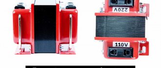
Operating principle and characteristics of midpoint transformers, connection
Connecting the meter via current transformers
By design and design, current transformers used in measuring circuits are divided into:
- Built-in. Their primary winding serves as an element for another device. They are installed on the inputs and have only a secondary winding. The function of the primary winding is performed by another current-carrying element of the linear input. Structurally, this is a ring-type magnetic circuit, and its windings have taps corresponding to different transformation ratios;
- Supporting. Designed for mounting and installation on a flat supporting plane;
- Passage. In terms of its structure, it is the same built-in, only it can be located outside another electrical device;
- Tire. The primary winding is one or more buses connected to one phase. Their insulation is calculated with a margin so that it can withstand even a multiple increase in voltage;
- Bushing. This is both a pass-through and a bus current transformer;
- Sectional. Its magnetic circuit consists of collapsible elements;
- Portable. Electricians call this device a current clamp. They are a portable and convenient measuring current transformer, in which the magnetic system opens and closes around the wire in which the current value needs to be measured.
When choosing a current transformer, the main thing to know is that when the rated current flows through the primary winding, its secondary winding, which is closed to the measuring device, will necessarily be 5 A. That is, if you need to measure current circuits where its calculated operating value will be approximately 200 A This means that when installing a 200/5 measuring transformer, the device will constantly show the upper measurement limits, this is inconvenient. It is necessary that the operating limits be approximately in the middle of the scale, so in this particular case you need to choose a 400/5 current transformer. This means that at 200 A of the rated current of the equipment on the secondary winding there will be 2.5 A and the device will display this value with a margin in the direction of increase or decrease. That is, even with changes in the controlled circuit, it will be visible to what extent this electrical equipment has left the normal operating mode.
Here are the main values that you should pay attention to when choosing measuring current transformers:
- Rated and maximum voltage in the primary winding;
- Rated value of primary current;
- AC frequency;
- The accuracy class is different for measurement and protection circuits.
Overhaul of transformers
As in matters of current repair, the main positions of capital repairs are also dictated by the type of specific unit and its design features.
However, the main provisions for overhauling transformers include:
opening the transformer - first, the oil is drained below the level of the cover, at least 20 - 30 cm, then after opening the oil unit, the magnetic conductor with windings can be removed;
Opening the tank
- inspecting the windings to identify damage to the insulation; it is easier to inspect a dry transformer, but this procedure is mandatory; if interturn short circuits, carbon deposits, etc. are detected, the winding is repaired or replaced;
- repair of the cover and roof elements - insulators, terminals, filters, dryers, taps, exhaust pipes, etc.;
- repair of power transformers involves checking the wedging and fixation of the coils on the yoke; if necessary, they are wedged and forced apart;
- for oil transformers, the liquid dielectric is cleaned, and if the analysis results are unsatisfactory, it is completely replaced;
- maintenance of power transformers in the scope of major repairs involves eliminating cracks or completely replacing pipes, radiators of the cooling system, installing new gaskets, etc.;
- mechanical removal of paint and application of a new layer of paint material;
- checking the status of additional devices;
- disassembling the active part with subsequent drying of its elements;
- checking operating parameters - transformation ratio, winding connection groups, current and no-load losses,
- testing the power circuits in the device, checking the insulation of the windings, measuring the dielectric loss tangent, etc.
Electrical tests
In some situations, when when repairing electrical equipment it is not possible to get the yoke of the electric machine, it is allowed to carry out a major overhaul with an external inspection. But in this case, the oil must be completely drained from the tank to provide access to the windings.
Power units after major overhauls with complete or partial replacement of windings are necessarily subjected to forced drying, regardless of the data obtained during testing.
Current and major repairs of transformers
During operation, individual parts of the transformer, under the influence of thermal, electrodynamic, mechanical and other influences, gradually lose their original properties and may become unusable.
In order to timely detect and eliminate developing defects and prevent emergency shutdowns, current and major repairs are periodically carried out for transformers.
Current repairs of the transformer are carried out in the following volume:
a) external inspection and elimination of detected defects that can be eliminated on site,
b) cleaning of insulators and tank,
c) draining dirt from the conservator, adding oil if necessary, checking the oil indicator,
d) checking the valve and seals,
e) inspection and cleaning of cooling devices,
f) checking gas protection,
g) checking the integrity of the exhaust pipe membrane,
h) carrying out measurements and tests.
For transformers with voltage regulation under load, extraordinary repairs of the regulating device are carried out in accordance with the instructions of the factory instructions, depending on the number of switchings made.
When repairing transformers with forced oil-water cooling, special attention should be paid to the absence of air leaks into the oil circulation system and to checking the tightness of the coolers.
The tightness of the coolers is checked by creating excess pressure alternately from the oil and then from the water system in accordance with current instructions.
The frequency of cleaning and testing of coolers depends on local conditions (water pollution, condition of coolers) and is carried out at least once a year.
During repairs, the condition of thermosiphon filters and air dryers is also checked.
When repairing oil-filled bushings of transformers, an oil sample is taken, oil is added, and, if necessary, the dielectric loss tangent is measured (at least once every 6 years).
Due to the fact that the oil in transformer bushings becomes unusable after several years of operation, during repairs it sometimes becomes necessary to change the bushing. Operating experience also shows that for oil-filled bushings with barrier insulation, after 10 - 12 years of operation on transformers, only changing the oil is not enough, but requires a major overhaul with disassembly, cleaning and, if necessary, replacement of the bushing insulation.
Overhaul of transformers
The transformer has sufficiently large reserves of electrical insulation strength and is a very reliable device in operation.
Transformers have oil barrier insulation. Pressed steel is used as the main solid insulation for the transformer. Pressed steel, produced until recently by domestic factories, shrinks over time, which is its significant drawback.
As a rule, a rigid winding pressing system is used for transformers, which does not automatically pre-press the winding as the press shrinks. Therefore, after several years of operation, major repairs are planned for transformers, during which the main attention should be paid to pre-pressing the windings.
In the absence of the necessary lifting devices, major repairs can be carried out by inspecting the core in the tank (with the cover removed), if it is possible to perform pre-pressing and wedging of the windings.
For critical transformers, the initial period of overhaul after commissioning is set at 6 years, for the rest - based on test results as necessary.
Overhaul of the transformer is carried out in the following scope:
a) opening the transformer, lifting the core (or removable tank) and inspecting it,
b) repair of the magnetic pipeline, windings (pre-pressing), switches and bends,
c) repair of the cover, expander, exhaust pipe (checking the integrity of the membrane), radiators, thermosiphon filter, air dryer, taps, insulators,
d) repair of cooling devices,
e) cleaning and painting the tank,
f) checking instrumentation, signaling and protective devices,
g) cleaning or changing the oil,
h) drying the active part (if necessary),
What about equipment for repairing transformers?
Current transformers tpl-10-m
When repairing a transformer, some operations can be performed manually using simple tools. Examples include taking oil samples, cleaning the insulators and tank, and tightening the nuts to restore the tightness of the seals between the tank and the lid. But, for example, it is impossible to top up transformer oil without special equipment. Before adding, the oil must be prepared (degassed, cleaned of impurities) and kept in this condition until it enters the transformer.
The GlobeCore company produces equipment that makes life much easier for organizations whose main specialization is the repair and maintenance of electrical equipment.
We recommend using the following models:
- ATC – a lightweight and maneuverable installation for adding degassed oil to the transformer;
- “Rime” – an installation designed for vacuuming power transformers and drying solid insulation;
- PPM – installation for heating transformer oil. This operation is performed before adding or changing oil;
- “Sukhovei” is a device that can be used to blow out the transformer tank with dry hot air. This action protects the insulation from moisture in the event of depressurization of the active part of the transformer, repair or maintenance;
- SMM – installations for degassing and purification of power transformer oils from mechanical impurities. They use combined methods of oil processing (exposure to temperature and vacuum, adsorbents, filtration), which always allows you to achieve the best result;
- SMM-R is a unit for restoring important operational parameters of electrical insulating oil. The equipment can be connected directly to a running transformer;
- TSS is a system for safely connecting oil processing units to a transformer. Allows you to monitor the oil level in the tank, the presence of leaks, and the presence of air in the connecting hoses.
GlobeCore regularly expands the functionality of its equipment. If transformer repair requires it, the installations can be equipped with additional sensors, as well as a monitoring and control system via mobile communications.
Stages of routine repair of an oil transformer
Current repairs usually begin with an external inspection. If any defects were identified, they are eliminated. Also, after a preliminary inspection, a number of other operations are performed: cleaning the insulators, radiators and tank, removing dirt from the conservator, adding oil, checking the reliability of connections, taking oil samples, etc.
It is very important to determine whether there is an oil leak in the transformer. It is usually formed due to a leak in the seal between the tank and the lid. To eliminate this phenomenon, you simply need to tighten the nuts. If this does not help, then replace the seals. It is advisable to use products made from oil-resistant rubber.
Dust and oil are removed from the tank and radiators. Gasoline is used to clean insulators. When topping up, it is important to consider that the temperature difference between the oil in the transformer and fresh oil should not exceed 5 ºC. The oil temperature is controlled by a special thermometer, which is located on the tank lid.
Attention is also paid to indicator silica gel. If the substance turns pink, the silica gel is replaced, which guarantees reliable operation of the air dryer. Spent silica gel is subjected to reduction. The regeneration procedure depends on the type of material: indicator or granular. In the first case, this is drying at a temperature of 100-120 ºС for 15-20 hours, and in the second - at 400-500 ºС for 2 hours. The first sign indicating the end of the recovery of indicator silica gel is the bright blue color of the adsorbent.
As for the thermosiphon filter, its recharging depends on the current value of the acid number of the oil. It is determined based on tests of samples taken. If the acid number exceeds 0.1 mg KOH/g, it is necessary:
- Drain the oil from the conservator.
- Remove the filter cover.
- Remove the grid with silica gel.
- Remove the used silica gel and replace it with new (dry) one.
Maintenance
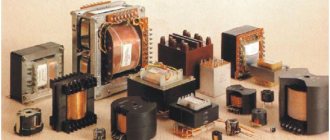
Types of transformers
The operation of instrument transformers is not a very complex and time-consuming process. The actions of the personnel consist mainly of monitoring the serviceability of its secondary circuits, the presence of protective grounding and the readings of control devices, as well as meters. Inspection is most often carried out visually; due to the danger of human injury from high voltage, entry beyond the fences where transformers are installed is strictly prohibited. However, this applies to a greater extent to systems with voltages above 1000 Volts. For low-voltage circuits, visual inspection for heating of connections, as well as corrosion of contact terminals, is an integral part of the work of electrical personnel. The most commonly used device for measuring current in 0.4 kV circuits is a current clamp. Since when calculating and developing starting equipment, stationary transformers are very rarely used for measurement.
In any case, you need to pay attention and take measures to eliminate detected defects such as:
- Detection of cracks in insulators and porcelain dielectric elements;
- Poor condition of reinforced seams;
- Crackling and discharges inside the device;
- Lack of grounding of the frame or secondary winding.
When carrying out maintenance of instrument transformers, on the switchboards where the devices are installed, you need to look not only at the readings of the devices, but also at the contact connections of the wires that are connected to them. By the way, their cross-section should not be less than 2.5 mm² for copper wires, and 4 mm² for aluminum.
Testing instrument transformers
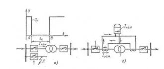
Testing of instrument transformers comes down to measuring the insulation resistance and transformation ratio, which is determined according to the following diagram.
In this case, a current of at least 20% of the rated one is supplied to the primary winding from a special load transformer or autotransformer. As is known, the transformation ratio will be equal to the ratio of the current in the primary winding to the current in the secondary. After which this value is compared with the nominal value. If the transformer has several secondary windings, then it is necessary to check each one. And we also must not forget about having the correct labeling.
The choice of current transformer required, as well as their test characteristics, are determined in laboratory conditions by special highly qualified electrical personnel, where the corresponding document is issued based on its results.
Output for repair of a power transformer sequence
During operation, any transformer, step-down or step-up, is taken out of operation emergency in the following cases:
- Internal crackling, which is characteristic of an electrical discharge between two oppositely polarized conductors;
- Abnormal or uneven noise that occurs both with and without load;
- In case of unreasonable heating, which increases even with rated load and proper cooling;
- In case of oil emissions, which can be from the expander or from a damaged exhaust pipe diaphragm;
- In case of severe oil leakage, as well as when the minimum permissible level is reached;
- After receiving bad results from a chemical analysis of the oil from the laboratory.
The sequence of actions of personnel when taking a transformer out of service for repair is clearly regulated and signed. Depending on local conditions and the switching circuit of the transformers, these switchings may differ slightly from each other, but the basic logical chain still remains the same. The main thing is that they must be carried out without consequences for the powered equipment and for sources consuming electricity, and also safely, that is, using both basic and additional personal protective equipment.
Here is the sequence of shutdowns and switchings in the circuit of a step-down three-phase oil or dry transformer of a substation in order to take it out for repair:
- If there is a sectional disconnector and an oil switch on the low side, then to ensure uninterrupted power supply to power consumers. in this case, the disconnector is turned on first and only then the sectional oil switch;
- The oil switch is turned off on the low side. Now both sections are powered by one transformer, which will power both sections during the repair of the other. Naturally, this is if there are only two of them, like transformers;
- The input oil switch is turned off, that is, on the high side;
- Now it is possible to provide a visible break to the power buses of a transformer being taken out for repair by disconnecting the linear or bus disconnectors;
- Portable grounding connections must be installed on the low and high sides, naturally, after directly checking the absence of voltage and posting safety posters.
Safety precautions when carrying out maintenance of transformers
- Before starting work, the specialist prepares the necessary tools and makes sure that they are in good working order;
- The work is carried out in special clothing with the obligatory use of means of protection against electric shock;
- To ensure safe work, the power supply to the camera being inspected is turned off. The camera switch is turned to the “off” position, a safety sign is hung on the switch that is turned off, warning people about the work;
- Next, the worker discharges the capacitors;
- Having opened the transformer chamber, the worker makes sure that there is no voltage at the LV output of the transformer.
Maintenance of dry-type power transformers
Dry power transformers with cast insulation are not difficult to handle. The maintenance schedule for a dry-type transformer largely depends on the operating conditions.
- Check the cooling system every six months. For forced-air cooling systems, check the fans and temperature controller.
- Clean the surface of the transfomator. If the transformer operates in a polluted environment, it needs to be cleaned more often. On average, you need to remove dirt from the device once every 3-6 months.
- Check the surface of the transformer for cracks once a year.
- Check the insulation and protection of metal parts of the transformer annually. If no chips or corrosion are found, then everything is fine.
- Look how tightly the windings are fixed. If you find damage in the cast winding, replace it.
Dry transformers are easier to maintain than oil transformers. The temperature and pressure in the oil tank must be constantly monitored. There are no liquids in an air-cooled transformer. Therefore, you invest less resources in its maintenance.
Features of repair of dry transformers
During the average repair of dry transformers, the windings and yokes of the magnetic system are pressed, all fasteners are tightened, insulators, fans and their electrical wiring, casing, clamps and a panel for switching adjustable taps are replaced or repaired, all parts and ventilation ducts are cleaned and blown with dry compressed air, and the resistance is measured. insulate windings, yoke beams, winding pressing parts and magnetic system ties, paint the casing, busbar bends and other parts that have damage to the anti-corrosion coating, measure the DC winding resistance and transformation ratio. When measuring insulation resistance, use a 1000V megohmmeter. The insulation resistance of windings at 20 - 30 °C for transformers with a rated voltage of up to 1 kV must be at least 100 MΩ, more than 1 to 6 kV - at least 300 MΩ, more than 6 kV - at least 500 MΩ. During a major overhaul, the windings are rewound or replaced, the frame and its magnetic system, main insulation parts are repaired, the taps are re-insulated, the varnish coating of the windings is dried, painted and baked, and all work related to medium repairs is performed, including electrical tests. The active part of dry transformers is dried in a cabinet or with a blower.
Disassembly of transformers
Disassembly of the transformer during major repairs is carried out in the following order. Drain the oil from the expander, remove the gas relay, safety pipe and expander; Place plugs on the holes in the tank lid. Using lifting mechanisms, the cover with the active part of the transformer is lifted using slings using lifting rings. Having raised it by 10 - 15 cm, inspect the condition and position of the sealing gasket, separate it from the tank frame with a knife and, if possible, save it for reuse. After this, the active part is removed from the tank in areas convenient for work on removing oil sludge, washing the windings and core with a stream of heated oil and defect detection. Then the active part is installed on a pre-prepared platform with a pallet. Having raised the active part of the transformer 20 cm above the level of the tank, move the tank to the side, and for ease of inspection and repair the active part is installed on a strong platform. The windings are cleaned of dirt and washed with a stream of transformer oil heated to 35 - 40 °C.
If the transformer has inputs located on the walls of the tank, then first remove the cover, drain the oil from the tank 10 cm below the input insulators and, having disconnected the inputs, remove the insulators, and then remove the active part from the tank.
Disassembly, inspection and repair of the transformer are carried out in a dry, closed room adapted for this work.
After removing the active part, the condition of the magnetic circuit is checked - assembly density and quality of the mixture, the strength of the yoke beams, the condition of the insulating sleeves, washers and gaskets, the degree of tightening of the nuts, studs, tie bolts, the condition of the grounding
Pay special attention to the condition of the windings - the wedging on the magnetic cores and the strength of the windings, the absence of signs of damage, the condition of the insulating parts, the strength of the terminal connections, dampers
During the period of major overhaul of the transformer, in addition to the listed work, if necessary, the yoke of the magnetic circuit is loosened, the iron is pressed out and the winding coils are removed.
Repair of dry transformers
The easiest way to repair dry three-voltage voltage transformers is to carry out repairs. Phases of repair work:
- It is necessary to press the winding and yoke of the system;
- Be sure to tighten all fastenings on the ventilation and tank;
- Check and, if necessary, replace the following mechanisms: insulator, casing, fan, spring beams;
- It is very important to blow dry air through all ventilation ducts of the device;
- And the last check is a study for the presence of rust. If necessary, damaged areas are cleaned and painted over with special paint. Pay special attention to the casings, tires, and magnetic system (ties).
Dry transformer circuit
Repair of instrument transformers
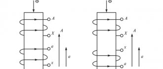
Routine repair of instrument transformers begins with cleaning them from dust and dirt, then inspecting porcelain, epoxy or other insulation, checking the reliability of their attachment to the structure, the volume of oil in the tank and the absence of leaks in seals and welds. To eliminate oil leaks, tighten the fastening bolts. If this does not help, install a new gasket made of oil-resistant rubber. If oil leaks through the welds, replace the transformer with a new one. They check the reliability of the connection of the transformer with the ground loop, the contact connections of external wires with the transformer, and the connections of the secondary windings with the ground. When repairing dismountable current transformers, check the absence of rust at the ends of the magnetic circuit. To do this, disconnect the conductors, unscrew the nuts of the fastening bolts and separate the halves of the transformer. The rust is removed with sandpaper, the halves are fastened with bolts, trying to ensure that there is no air gap between them and the cable is located in the center of the transformer window. In transformers, the insulation resistance is measured, the primary winding is measured with a megohmmeter at 2.5 kV, the secondary winding is measured at 1 kV. Insulation resistance is not standardized, however, for the secondary windings of a current transformer, a resistance of 50 - 100 MΩ is considered sufficient. If the insulation resistance of the windings is less than the specified value, the transformer is removed and dried. During major repairs, current transformers (CT) and voltage transformers (VT) are tested at increased voltage. When replacing transformers during repairs, tests are carried out, the integrity of their windings is checked, as well as the connection groups of three-phase and the polarity of single-phase transformers. As is known, the direction of the current in the winding of an AC ammeter does not affect the accuracy of its operation (with any method of connecting the ammeter to the CT, it will give correct readings). In devices such as wattmeters, electricity meters, and many relay protection devices, the direction of the current is of great importance. Therefore, the CT windings have special markings that allow it to be correctly connected to the primary high-voltage circuit and to the secondary measuring circuit. Thus, the beginning and end of the primary winding are marked L1 and L2 (line), respectively, and the beginning and end of the secondary winding are marked I1 and I2 (current measuring circuit). The VT terminals are marked as follows: the beginning and end of the primary winding are designated A and X, respectively, and the beginning and end of the secondary winding are designated a and x.
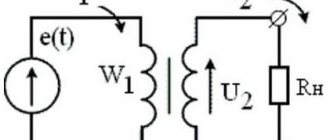
Rice. 11. Scheme for checking the polarity of the measuring transformer: GB - battery; S - switch; P—galvanometer (polarimer); w1, w2 - primary and secondary windings
The integrity of the windings and the correctness of their connection are checked with a megohmmeter, and the polarity is determined according to the diagram shown in Fig. 11. With the correct designation of the terminals, the needle of the galvanometer (polarimeter) P should deviate to the right at the moment of closing switch 5. Transformers with incorrectly labeled terminals are sent for relabeling. When checking the integrity of the secondary winding, short-circuit the primary winding, since when the primary winding is open, a large electromotive force will be induced in it, which is dangerous both for humans and for the insulation of the winding.
How to repair instrument transformers
A mandatory requirement is to prepare a special room (workshop or at least a garage) for repairs and testing. It is necessary to clean the epoxy and porcelain insulation from accumulated dust, dirt and grease, check the strength of their fastening and the joints for cracks. The following steps are taken next:
- Checking the presence of oil in the tank and its quantities. If a leak is noticed, then you need to tighten the bolts more tightly and coat the joints with sealant. In the case when the transformer passes oil through the welded seams, it needs to be completely replaced and cannot be repaired;
- Check the connection between the transformer and grounding. In particular, the secondary winding and ground loop;
- Presence of corrosion processes at the ends and bolted connections. If any, they must be removed by using sandpaper or a wire brush;
- Check the resistance of insulating materials. To do this, you will need a special device - a megaohmmeter, designed on the principle of a multimeter. The norm is 1 kV for the primary winding and 2.5 for the secondary.
Current distribution in windings
Instrument transformer diagram
Transformers are tested after repair using high voltages. Using such tests, you can check the correctness of three-phase connections and the polarity of devices.
1.2. Specifications.
Power transformers in power supply networks are used to convert voltage to the value at which electrical receivers operate.
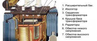
At central and workshop transformer stations, two-winding three-phase transformers with natural oil cooling are widely used (Figure 4, A2 format).
The transformer has two main parts:
active removable, consisting of a magnetic circuit 12 with windings 10 and 11;
external, including tank 1 with lid 2, oil conservator 8 and auxiliary devices.
The magnetic core (core) has two yokes: upper and lower, connected to each other by three rods on which the windings are located.
The windings are located concentrically on the core rods: low voltage windings 11 are adjacent to the rod, and high voltage windings 10 are placed on them; the windings are separated from one another by a layer of electrical cardboard. The ends of the high and low voltage windings are connected to bushings 3 and 4, fixed in the transformer cover.
From the higher voltage windings, in addition to the main ones, additional leads are made that are connected to the switch under the transformer cover. Switch handle 5 is installed on the transformer cover.
The switch allows you to change the transformation ratio of the transformer within +/- 5% and thereby regulate the voltage on the secondary winding to the nominal one.
The transformer tank is a reservoir for oil; its surface cools the oil and protects the active removable part from external influences. The tanks of transformers with a power of up to 50 kVA are made smooth; the tanks of more powerful transformers have tubular radiators that improve the cooling conditions of the transformers.
Current repair of transformers
It should be noted that the list of work performed is determined by factory or industry instructions, directions, technological maps, etc., but their provisions cannot conflict with PTEEP.
However, the common features for routine transformer repair are the following operations:
- technical inspection, during which it is necessary to identify external defects and take measures to eliminate them;
- mechanical cleaning of the walls and lids of tanks, grooves or tubes of radiators, insulators, etc.;
- removing clogs from the tank, as a rule, all the debris collects at the bottom, so when unscrewing the plug from the expander or main tank of the transformer, they will flow out first;
- determining the oil level by arrow readings or position in the oil indicator glass, comparing the height with the ambient temperature, topping up if necessary;
- checking the movement of valves and shut-off valves;
- if the oil tank has separate radiators, they are also checked for density, tightness, and absence of leaks;
- as part of routine repairs for power oil transformers, gas protections are checked;
Checking the gas relay
- if there are exhaust pipes, inspect the condition of the membrane for activation;
- checking and testing the oil - breakdown, chemical analysis, flash point check;
- electrical tests of windings and other elements of the power transformer, checking the quality of contacts, tightening bolts.
Checking bolted connections
For those transformer models that contain adjusting devices (on-load tap-changers, off-load tap-changers), it is necessary to carry out routine maintenance on the regulators. This includes all kinds of scrolling, testing of protections, etc.
For transformers with forced air flow or other forced cooling systems, the corresponding equipment is repaired and tested. For electric motors, the insulation condition is checked; in transformer water cooling systems, the tightness is checked.
For most units, including measuring ones, the silica gel present in the filters is replaced or dried. The same manipulations apply to oil-filled bushings. Before the start of each shift, these filters are inspected to monitor the condition of the silica gel in them.
Current repair of air-cooled transformer
Current repair of a dry-type transformer has some differences. After removing the casing, make sure that there is no mechanical damage to the windings and other important parts. The reliability of connections and grounding is also monitored. During routine repairs, it is advisable to purge the dry transformer with air and also wipe the insulators.
The procedure for measuring the resistance of insulator windings does not directly relate to routine repairs. But it is mandatory after its completion.
Switch repair
Switch repair consists of eliminating defects in contact connections, cylinder insulating tubes and sealing devices. The contacts are cleaned and washed with acetone and transformer oil. Burnt and melted contacts are filed with a file. Damaged and burnt contacts are replaced with new ones. Minor damage to the insulation of the tube or cylinder is restored with two layers of bakelite varnish. Weak connection points of winding taps are soldered with POS-30 solder.
The repaired switch is assembled, the installation site is wiped with a rag, the gland seal is inspected, the switch handle is put in place and the studs are tightened. The quality of operation of the switch is checked by switching its positions. Shifts must be clear, and the locking pins must fully fit into their sockets in all positions.
Checking the operation of the switching device for voltage regulation under load consists of determining the correct sequential operation of the moving contacts and
and
b
switch and contactors K1 and K2. Violation of the sequence of operation of these elements of the switching device can lead to serious damage to the transformer and an accident in the electrical network.
Current repairs of power transformers
The scope of work performed during routine repairs includes:
- Thorough external inspection;
- Cleaning the body, wiping insulators;
- Tightening of all bolted connections, special attention should be paid to current-carrying connections; if they are oxidized, they must be unscrewed, cleaned and re-tightened;
- Checking the cooling system and the operation of the oil indicator device;
- Activation of gas protection and cleaning of block contacts in it;
- If there are automatic cooling devices, it is necessary to check their operation and functionality;
- Draining water and condensate from the expander sump;
- Checking the moisture level of silica gel. Pink particles must be replaced with new ones;
- Add oil to the expansion tank if necessary;
- Measuring the insulation resistance, this procedure is performed with a megger rated for a voltage of 2500 Volts. The instrument error should not exceed 10–15%.
If minor faults are noticed between routine repairs during operation, they must be corrected by repair personnel. In this case, the number of components and parts that must be replaced with new ones should be minimal.
During routine repairs of dry transformers, it is necessary to remove the casing and make sure that there is no electrical heating or mechanical damage to all its parts. After covering, be sure to blow with compressed air, only after that put the casing back. Repair of a pulse transformer due to its small dimensions can be carried out even at home.
Transformer tank repair
The inner surface of the tank is cleaned with a metal scraper and washed with used transformer oil. The dents are heated with a gas burner flame and straightened with hammer blows. Cracks on the rib and wall of the housing are welded using gas welding, and in the pipe - using electric welding. To check the quality of welding, the outer side of the seam is cleaned and covered with chalk, and the inside is moistened with kerosene (if there are cracks, the chalk is moistened with kerosene and darkens). The tightness of the housing is checked by filling the tank with used oil for 1 hour at a temperature not lower than 10°C.
Before welding the crack, through holes with a diameter of several millimeters are drilled at its ends. The edges of the crack are chamfered and welded using electric welding. The tightness of the seam is controlled using kerosene. Loose seams are cut out and welded again.
Preventive repair of transformers
In addition to the listed interventions, there is also the so-called preventive repair, which can be performed without or with lifting the active part. Such repairs relate to preventive measures and represent a periodic inspection of the transformer with the subsequent elimination of detected minor defects.
Refurbishment of transformers in comparison with reconstruction and modernization is considered the simplest. When performing it, the main task comes down to knowledge of a certain technology and the ability to use it in practice. It is necessary to ensure that everything is carried out as previously done by the manufacturer. Any deviations from existing technology must be carefully thought out, not disrupt the performance of the equipment and not affect the quality indicators of the transformer.
Rate this article:
Repair of welding transformers
Before proceeding directly to repairing the welding transformer, you should make sure that the terminals for connecting the power wire are not burned. The terminal block to which the ends of the welding wires are connected is the weakest point of this device. Phase short circuits of the windings are rare; most often these are short circuits to a grounded frame, and if they do occur, then strong heating will be observed. That is, when repairing welding transformers, you need to pay special attention to all bolted connections, since after all, the welding process is associated with the constant operation of the transformer in short circuit mode. This repair is also aimed at revising the mechanism connecting the core and securely securing the windings to the magnetic core. Repairing windings is a very rare procedure and it comes down to applying a special varnish to damaged areas or completely replacing it with a new one.
High-quality current and overhaul repairs of transformers, carried out in full, often become the main component of its long-term, trouble-free operation.