Transformer characteristics
The design of the box with the transformer can be very diverse. The main element of the mechanism is a ferromagnetic core, the windings of which are framed by a special copper conductor. The primary part of the winding controls the voltage in the network, while the secondary is responsible for removing the reduced voltage.
The core emits alternating current, which creates a coupling between the two existing windings. The windings are not connected to each other by electric current. By the way, the ability to reduce tension arises due to the difference in the number of curls between these components.
Most often, these elements are protected by a special case, however, the structural features and varieties allow for various variations.
What is a power transformer
Two or more windings are put on a closed core (magnetic core), made of steel sheets, one of which is connected to an alternating current source. The other (or other) winding is connected to the consumer of electric current - the load. The alternating current passing through the primary winding creates a magnetic flux in the steel core, which induces an alternating voltage in each turn of the winding - coil. The voltages of all turns add up to the output voltage of the transformer. The shape of the core - magnetic circuit, can be W-shaped, O-shaped and toroidal, in the form of a torus. Thus, in a power transformer, electrical power from the primary winding is transferred to the secondary winding through the magnetic flux in the magnetic core.
It will be interesting➡ Design and circuit of a three-phase transformer
There are a lot of consumers of electrical energy: electric lighting, electric heaters, radio and television equipment, electric motors and much more. And all these devices require different voltages (AC and DC) and different powers. This problem is easily solved using a transformer. From a household network with an alternating voltage of 220 volts, you can obtain an alternating voltage of any value and, if necessary, convert it into direct voltage.
The efficiency of the transformer is quite high, from 0.9 to 0.98 and depends on losses in the magnetic circuit and on magnetic stray fields. The cross-sectional area of the magnetic circuit S depends on the magnitude of the electrical power P. Based on the value of the area S, the number of turns w per 1 volt is determined when calculating the transformer:
w = 50/S.
The power of the transformer Рс is selected from the required load value Рн plus the value of losses in the core.
When calculating a transformer, with a certain degree of accuracy, we can assume that the load power in the secondary winding Pн = Un * Iн and the power consumed from the network in the primary winding Pc = Uc * Ic are approximately equal. If losses in the core are neglected, then the equality is obtained: k = Uс / Un = Iн / Iс.
Transformers and their application/
Design features
This is a very useful device. A transformer is a device that consists of a core with two windings. They must have the same number of turns, and the core itself is made of electrical steel. Voltage is applied to the input of the device, an electromotive force appears in the winding, which creates a magnetic field.
The basic principle of operation of the device.
The turns of one of the coils pass through this field, due to which a self-inductive force arises. In the other, a voltage arises that differs from the primary by as many times as the number of turns of both windings differs.
With its help, we can easily reduce the voltage and current in AC circuits. The advent of transformers made the transmission of electricity over long distances a practical reality. Transformers make it possible to reduce losses on the wires of power lines (connecting generating stations with loads) to reduce alternating current.
At both ends (both the generator and the loads), transformers step down voltage levels to safer values and reduce the cost of the equipment involved.
A step-down transformer can be of various types and types: single or three-phase, with an open housing or with a protective casing. One of the most important characteristics of the device is the transformation ratio, which should not exceed 1. Basic facts about step-down transformers are shown in the figure below.
Basic facts about step-down transformers.
Depending on the modification, the device converts electric current of different initial voltages, which can reach 660V. The transformer that steps down to 220V is most widely used. There is also a transformer that steps down to 380 volts.
A magnetic core is a set of elements of ferromagnetic material (usually electrical steel), which are assembled in a certain geometric shape. The main magnetic field of the step-down transformer is localized in it.
The entire magnetic system, together with all its components, is called the core. In this case, the part where the main windings are located is called the rod. And the part needed to complete the magnetic circuit is the yoke.
In accordance with the arrangement of the rods in space, the step-down transformer can have a flat, spatial, symmetrical or asymmetrical magnetic system.
In accordance with the requirements for each case, the output voltage can be different: for example, a transformer that reduces to 36 Volts, as well as 12, 24, 42V, etc. The video describes in detail the principle of operation of the device.
Which core is better
Step-down voltage transformers differ in their design features. Manufacturers make a choice in favor of one of two concepts - armored or rod.
The fundamental difference between the technical solutions is that in the first case, the windings are enclosed in an armor-type core, and in the second, the core is enclosed in rod-type windings.
Moreover, in devices of the first type, the axis of the windings can be located vertically or horizontally, while in the second case, the axis is placed vertically.
It will be interesting➡ What is a pulse transformer and how to calculate it
However, the production method does not affect the performance and reliability of the device. The enterprise chooses the option that it considers best from the point of view of organizing the technological process.
Core and coils of a step-down transformer.
Transformer functions
So, why do we need step-down transformers? Let's start with the fact that very often this mechanism regulates the voltage in the network in industrial buildings.
Thus, the 220 V step-down transformer has found wide application in industry and households. In addition to their everyday use, these designs reduce the voltage in power lines and regulate the operation of the current.
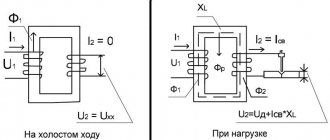
Transformer operating modes
There are three operating modes of the transformer: idle mode, short circuit mode, operating mode. The transformer is “idling” when the leads from the secondary windings are not connected anywhere. If the transformer core is made of a soft magnetic material, then the no-load current shows what losses occur in the transformer due to magnetization reversal of the core and eddy currents.
In short circuit mode, the terminals of the secondary winding are short-circuited together, and a small voltage is applied to the primary winding, so that the short circuit current is equal to the rated current of the transformer. The amount of loss (power) can be calculated if the voltage in the secondary winding is multiplied by the short circuit current. This transformer mode finds its technical application in instrument transformers.
If you connect a load to the secondary winding, a current appears in it, inducing a magnetic flux directed opposite to the magnetic flux in the primary winding. Now, in the primary winding, the EMF of the power source and the induced emf of the supply are not equal, so the current in the primary winding increases until the magnetic flux reaches its previous value.
Transformer operating modes.
For a transformer in active load mode, the following equality is true: U_2/U_1 =N_2/N_1, where U2, U1 are the instantaneous voltages at the ends of the secondary and primary windings, and N1, N2 are the number of turns in the primary and secondary windings. If U2 > U1, the transformer is called a step-up transformer, otherwise we have a step-down transformer. Any transformer is usually characterized by the number k, where k is the transformation ratio.
It will be interesting➡ Idle mode for transformers
How to choose a step-down transformer?
There are many varieties and types of transformers, but when choosing them, you should pay attention to the following characteristics:
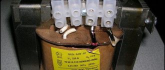
- Incoming voltage parameter, the parameter of which is usually marked on the product body. For domestic purposes, a 220 V transformer is used.
- Markings on the device body should also indicate the amount of output energy. In order to become more familiar with the features of the case and markings, we recommend that you familiarize yourself with photos of step-down transformers on the Internet.
- Make the following calculations to correctly select the power characteristics. Add up the energy value of all devices that will be connected to the device and add another 20%.
Transformers and their applications
A transformer is a device used to increase or decrease alternating voltage without changing its frequency and with virtually no power loss. A transformer consists of two or more coils mounted on a common core. The coil that is connected to the AC voltage source is called primary, and the coil to which the load (consumers of electrical energy) is connected is called secondary. Transformer cores are made of electrical steel and assembled from separate plates insulated from each other (to reduce energy losses due to the occurrence of eddy currents in the core).
Transformer coils typically contain different numbers of turns, with more voltage being applied to the coil with more turns. If a transformer is used to increase voltage, the winding with fewer turns is connected to the voltage source, and the winding with more turns is connected to the load. To lower the voltage, everything is done the other way around. At the same time, we should not forget that no more than the rated voltage (the one for which it is designed) can be applied to the primary winding.
The transformation ratio is the ratio of the number of turns in the primary winding to the number of turns in the secondary winding. It is also equal to the ratio of the EMF in the windings. In the absence of losses in the windings, the transformation coefficient is equal to the ratio of the voltages at the winding terminals: k=U1/U2. For a step-down transformer, the transformation ratio is greater than 1, and for a step-up transformer, it is less than 1. The operating principle of the transformer is based on the phenomenon of electromagnetic induction. When alternating current flows through the primary coil, an alternating magnetic field and magnetic flux arise around it, which also penetrates the second coil. As a result, a vortex electric field appears in the secondary coil and an induced emf appears at its terminals.
The transformer is characterized by an efficiency equal to the ratio of the power released in the secondary coil to the power consumed by the primary coil from the network. Good transformers have an efficiency of 99 - 99.5%. An important property of a transformer is its ability to transform load resistance. Consider a transformer with an efficiency of approximately 100%. In this case, the power released in the secondary circuit of the transformer will be equal to the power consumed by the primary winding from the voltage source. For such a transformer, the power consumed from the voltage source will be purely active. Power in the primary circuit of the transformer P1=(U12)/R1, and in the secondary circuit P2=(U22)/R2.
It will be interesting➡ What is a pulse transformer and how to calculate it
Since P1=P2 and U1=kU2, then R1=k2R2.
Thus, a load with resistance R2 connected to an alternating voltage source through a transformer will be equivalent in power to a load with resistance R1 connected without a transformer. Laboratory autotransformers are widely used to regulate alternating voltage. Autotransformers are designed for connection to an alternating voltage network of 220 V or 127 V. As a rule, the output voltage of the autotransformer is smoothly regulated up to 250 V.
The transformer winding is made of insulated wire in one layer. In areas of the winding that are touched by the moving contact with the carbon insert, the insulation is cleaned. When the contact moves, the carbon insert short-circuits a turn of wire. However, due to the small voltage on one turn and the noticeable resistance of the carbon insert, an allowable current flows through the closed turn.
The primary winding of an autotransformer is part of its secondary winding and therefore there is a galvanic connection between the primary and secondary windings of the transformer. Consumers cannot be directly connected to the secondary winding of the autotransformer, one of the wires of which may be connected to ground. This connection will lead to an accident or mishap. When working with an autotransformer, it is prohibited to ground the secondary circuit. Let us briefly consider the simplest calculation of low-power transformers for household radio equipment.
The power of the transformer (in W) is numerically equal to the square of the area (in cm2) of the cross section of the middle core of the magnetic core. Knowing the rated power of the transformer, you can find the current in the primary winding at the rated load in the secondary windings. The diameter of the winding wire is selected based on (2.5-3) A/mm2 of the wire cross-section. For standard magnetic cores used for the manufacture of transformers, the number of turns per 1 volt is approximately equal to the quotient of 50 divided by the cross-sectional area of the central core of the magnetic core, expressed in cm2. However, depending on the quality of the magnetic core, the coefficient can vary from 35 to 65.
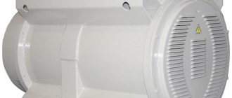
Transformer.
The total resistance of an inductor with a ferromagnetic core depends on the strength of the current flowing through it. The resistance of the coil, depending on the strength of the flowing current, first increases, reaches a maximum value, and then decreases. The nonlinear increase in no-load current depending on the voltage applied to the primary winding begins at approximately 0.8 Un. The rated voltage of the primary winding of the transformer is selected so that the no-load current is 5-10% of the rated current. At a voltage of 1.1 Un, the no-load current should not exceed 20-25% of the rated current of the loaded transformer.
Material on the topic: how a toroidal transformer works and what are its advantages.
Pros and cons of transformers
This technique has its advantages and disadvantages. When choosing certain models, you need to take into account all the nuances. Let's start with the pros:
- Human safety at home and in industrial environments is guaranteed by this mechanism, which reduces the level of electric current intensity to 12 V, thereby guaranteeing the preservation of life and health.
- The input voltage does not matter too much since the output current is stable.
- Compact and miniature box.
- Easy to move and install.
- Low heating of the case.
- Accurate voltage regulation.
- Not too long a service time.
- High price.
- Insufficient power.
Practical significance
The practical significance of the above becomes more apparent when the alternative is considered: before the advent of efficient transformers, conversion of voltage and current levels could only be achieved through the use of installations containing motors and generators.
While both the motor and generator are quite efficient units, using them in combination does not provide sufficient efficiency, so that the overall efficiency of the installation is in the range of 90% or less.
Transformer circuit in a simple charger.
In addition, the moving parts of these installations are subject to friction and mechanical wear, which in turn affects both service life and performance. Transformers, on the other hand, are capable of converting alternating voltage and current with very high efficiency without moving parts, making possible the widespread distribution and use of electricity that we take for granted.
It's fair to say that motor/generator units are not necessarily obsolete compared to transformers in all applications.
While transformers are clearly superior to motors/generators in converting AC voltage and current, they cannot convert one frequency of AC to another, nor can they convert (by themselves) DC to AC or vice versa.
It will be interesting➡ Necessary conditions for parallel operation of transformers
Motor/generator setups can do all this with relative ease, although with some of the efficiency limitations described above. These installations also have the unique property of storing kinetic energy.
That is, if for any reason the motor's power supply is instantly turned off, its angular momentum (inertia of rotational motion) will continue to maintain the rotation of the generator for some time, thereby isolating the load (powered by the generator) from “failures” in the main power system.
Photo of a step-down transformer
Homemade 12 volt power supply: selection of components and simple circuits for creating with your own hands. 130 photos of homemade universal blocksReinforcing shears (bolt cutters): types, characteristics, main differences
How a voltage control relay works: the principle of operation of the protection and the nuances of connecting a control relay for a house or apartment
What is a pulse relay: principle of operation, types, description of devices and connection diagrams. 155 photos of pulse-type relays and video installation instructionsPhoto relay for street lighting - selection criteria, tips for connecting and placing the device (135 photos)
Pulse protection device: classification, limiter connection diagram and tips for choosing a device (155 photos)
Did you like the article? Share

0
How to make a device from 220 to 12 volts with your own hands
Despite the fact that this device seems at first glance to be a complex device, you can assemble it yourself. The assembly procedure for such a device is very simple. First you need to do some calculations and you can get to work. In order to quickly and easily wind the coils, you need to make a simple device from a board, stands and a handle.
Sample of a homemade device.
First, the characteristics and number of turns on the windings of the device are calculated. In this case, the primary network voltage is 220 V.
It will be interesting➡ What is the difference between voltage transformers and current transformers
It is planned to obtain 12 V using the device, with a cross-sectional area of 6 square centimeters, which means a formula is drawn up with the following calculations:
the constant value of the average transformer iron is 60, which should be divided by the area.
The result is 10 - this is the number of turns per volt. The resulting number is multiplied by 220 - this is the number of turns of the primary winding. The number of turns of the second must be calculated according to the same principle: the resulting 10 turns are multiplied by 12 V.
The core can be made from tin cans; to do this, you need to cut strips up to 30 cm long and 2 cm wide. These blanks are fired in an oven over a fire, after which they cool and the scale needs to be cleaned off the surface. Apply varnish and stick strips of paper on one side.
Read material on the topic: How to assemble a step-up transformer with your own hands.
It is also necessary to prepare a paper-insulated wire with a cross-section of 0.3 mm. The secondary winding will be made of wire with a cross section of 1 mm. Use thick cardboard to make the base for the reel. Wrap paraffin paper on it and after that you can start winding the wire.
An example of a connection diagram for a step-down transformer 220 to 12 V.
After every two rows you need to lay a layer of this paper. The secondary winding is wound in the same direction as the first.
Iron strips must be inserted into the finished coil; they should go half their length. These strips cover the base, and the ends are connected at the bottom.
A small distance is left near the core and frame. It is better to make the base for the lowering device from an ordinary board up to 50 mm thick.
It is better to fasten parts using large metal brackets. This must be done so that the brackets go around the bottom of the core. The last step is to bring the ends of the windings onto the frame and secure them with contacts.
To make it easier to wind the coils (factories use special equipment for this), you can use two wooden stands mounted on a board and a metal axle threaded between the holes in the stands. At one end, the metal rod should be bent in the form of a handle.