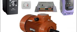
Asynchronous electric motor with wound rotor
An asynchronous electric motor is a very common electrical machine.
It is easy to manufacture and maintain, and due to its simplicity of design, it is very reliable. But it has one drawback - the angular speed of the shaft rotation is constant and depends on the number of poles of the stator winding. But what if you need to change the rotation speed during operation? The need to adjust speed is mainly required for electric motors installed on cranes . They perform the following main functions there:
- moving the crane (crane bridge) along rails;
- movement of the crane trolley (in a plane perpendicular to the rails);
- lifting the load.
Two motors (at both ends of the bridge) can be used to move the crane bridge. To lift the load, two hooks of different lifting capacity, lifted by different electric motors, can be used. One hook can have two ranges of lifting speeds, and also use two electric motors for this.
Overhead crane
There are other mechanisms whose rotation speed needs to be controlled: conveyors, fans.
Another reason to change the rotation speed of an electric motor is the need for its smooth acceleration . At the moment of switching on, it consumes a current several times higher than the rated one. It is called inrush current. If at the same time the motor load is heavy and also accelerates with difficulty, then the motor starting time increases, and the starting currents heat the stator winding and can damage it. And the electric motor shaft and its bearings experience mechanical loads that reduce their service life.
DC motors are capable of changing the speed of rotation of the shaft . To do this, rheostats are switched on in the circuits of their windings. This method of solving the problem is used in electrified transport: trams, trolleybuses, electric trains, metro. But the entire energy supply infrastructure for these consumers is organized in a special way, because direct current has its own characteristics. It is not profitable to use direct current in enterprises, the majority of whose consumers operate from a three-phase alternating current network . And DC electric motors themselves have plenty of shortcomings: a complex brush apparatus, maintenance of the commutator. Rheostats get hot, and remote control of several rheostats at once is difficult.
Therefore, in such mechanisms, asynchronous electric motors with a wound rotor are used.
Design and principle of operation of an asynchronous motor
The main components of an asynchronous electric motor are the stator and rotor, which are separated from each other by an air gap. The active work in the engine is performed by the windings and the rotor core.
Motor asynchrony is understood as the difference between the rotor speed and the speed of the electromagnetic field.
The stator is the stationary part of the engine, the core of which is made of electrical steel and mounted in the frame. The bed is made by casting from a material that is not magnetic (cast iron, aluminum). The stator windings are a three-phase system in which the wires are laid in grooves with a deflection angle of 120 degrees. The phases of the windings are usually connected to the network using a star or delta circuit.
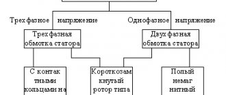
The rotor is the moving part of the engine. The rotors of asynchronous electric motors come in two types: squirrel-cage and slip-ring rotors. These types differ in the design of the rotor winding.
Squirrel-cage induction motor
This type of electric machine was first patented by M.O. Dolivo-Dobrovolsky is popularly called the “squirrel wheel” because of the appearance of the structure. The short-circuited rotor winding consists of copper (aluminum, brass) rods short-circuited using rings and inserted into the grooves of the rotor core winding. This type of rotor does not have moving contacts, so such motors are very reliable and durable during operation.
Asynchronous motor with wound rotor
This device allows you to adjust the operating speed over a wide range. The phase rotor is a three-phase winding that is connected in a star or delta circuit. Such electric motors have special brushes in their design, with which you can regulate the speed of the rotor. If you add a special rheostat to the mechanism of such an engine, then when starting the engine, the active resistance will decrease and thereby reduce the starting currents, which have a detrimental effect on the electrical network and the device itself.
Operating principle
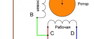
When electric current is applied to the stator windings, a magnetic flux occurs. Since the phases are shifted relative to each other by 120 degrees, this causes the flux in the windings to rotate. If the rotor is short-circuited, then with such rotation a current appears in the rotor, which creates an electromagnetic field. By interacting with each other, the magnetic fields of the rotor and stator cause the rotor of the electric motor to rotate. If the rotor is phase, then voltage is applied to the stator and rotor simultaneously, a magnetic field appears in each mechanism, they interact with each other and rotate the rotor.
Operating principle of an asynchronous electric motor with a wound rotor
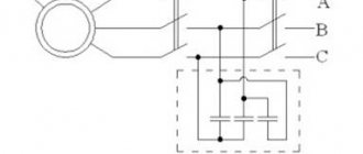
The stator of this electric motor is no different from a conventional one. But windings of three phases are added to its rotor, connected in a star, the ends of which are brought out to slip rings . Brushes slide along the rings, with the help of which the windings are connected to the electrical circuit.
Slip rotor
A squirrel-cage induction motor works like this:
- the current in the stator windings creates a rotating magnetic flux inside it;
- a time-varying magnetic flux, crossing the turns of the rotor winding, induces an EMF in them;
- since the rotor winding is closed, a current arises in it due to the induced EMF;
- The conductors of the rotor winding with current interact with the rotating field of the stator, creating a torque.
A feature of an asynchronous motor with a wound rotor: the current in the rotor can be changed by connecting resistors in series with its windings . The greater the resistance of the resistor, the less current in the rotor. As the current decreases, the force of interaction with the rotating field of the stator also decreases. The rotation speed drops.
The presence of resistors in the rotor circuit increases the volume of engine control gear . The power that is dissipated by them increases with the power of the electric motor. But even for small motors it is significant, which leads to bulky designs of resistance stores and the need to provide them with constant cooling. Resistors are made from materials with high resistivity. Their conductors are wound on frames or mounted on porcelain insulators. The structure is placed in a casing with louvered holes for cooling or covered with a mesh.
Shop resistors for crane motor with wound rotor
It is not always possible to place resistors indoors. On cranes they are located directly on the bridge, which leads to massive accumulation of dust inside them and the need for frequent maintenance.
There is no smooth adjustment of the speed of an electric motor with a wound rotor. The resistance in the rotor circuit changes in fixed steps . To do this, resistors are divided into sections connected in series, in the circuits of which control contactors are installed. If it is necessary to increase the rotation speed, the contactors bypass some of the resistors, reducing their total resistance. To achieve the maximum rotation speed, all resistors are shunted; for the minimum, nothing is shunted.
Asynchronous electric motor with wound rotor
Now let's look at several examples of constructing control circuits for an asynchronous motor with a wound rotor.
Three-phase asynchronous motor device
Main types of engines. By design, asynchronous motors are divided into two main types: with a squirrel cage rotor and a wound rotor (the latter are also called slip ring motors). The motors under consideration have the same stator design and differ only in the design of the rotor winding.
Motors with a squirrel-cage rotor (Fig. 1, a
and
b).
The stator contains a three-phase winding, which, when connected to a three-phase current network, creates a rotating magnetic field.
The rotor winding is made in the form of a squirrel cage, is short-circuited and has no leads (Fig. 1, c
).
The squirrel cage consists of copper or aluminum rods short-circuited at the ends with two rings (Fig. 2, a
).
The rods of this winding are inserted into the slots of the rotor core without any insulation. In low and medium power engines, a squirrel cage is usually obtained by pouring molten aluminum alloy into the grooves of the rotor core (Fig. 2, 6
). Together with the rods of the squirrel cage, short-circuiting rings and end blades are cast, which ventilate the machine.
| Rice. 1. Design of an asynchronous motor with a squirrel-cage rotor (a, b) and its connection diagram ( c ): 1 - housing; 2 - stator core; 3 — rotor core; 4 - rotor winding - squirrel cage; 5 - stator winding; 6 — rotor ventilation blades; 7 — bearing shield; 8 — fan casing; 9 - fan |
Aluminum is especially suitable for this purpose, since it has low density, low fusibility and fairly high electrical conductivity. In high-power machines, the slots of the squirrel-cage rotor are made semi-closed, in low-power machines - closed. Both groove shapes make it possible to strengthen the conductors of the rotor winding well, although they somewhat increase the leakage fluxes and inductive resistance of the rotor winding. In high-power engines, the squirrel cage is made of copper rods, the ends of which are welded into short-circuiting rings (Fig. 2, c). The different shapes of the rotor slots are shown in Fig. 2, g.
Electrically, a squirrel cage is a multiphase winding connected according to the Υ circuit and short-circuited. Number of winding phases m
2 is equal to the number of rotor slots
z
2, and each “phase” includes one rod and adjacent sections of short-circuit rings.
Often, wound and squirrel cage induction motors have chamfered slots on the stator or rotor. The bevel of the slots is done in order to reduce the higher harmonic EMF caused by magnetic flux pulsations due to the presence of teeth, reduce noise caused by magnetic causes, and eliminate the phenomenon of sticking of the rotor to the stator, which is sometimes observed in micromotors.
| Rice. 2. Design of a squirrel-cage rotor: 1 - rotor core; 2 — rods; 3 — fan blades; 4 — short-circuit rings |
Motors with wound rotor (Fig. 3, a
).
The stator winding is made in the same way as in motors with a squirrel-cage rotor. The rotor has a three-phase winding with the same number of poles. The rotor winding is usually connected according to the Υ circuit, the three ends of which are connected to three slip rings (Fig. 3, 6
), rotating together with the machine shaft. Using metal-graphite brushes sliding along slip rings, a starting or ballast rheostat is included in the rotor, i.e., additional active resistance is introduced into each phase of the rotor.
| Rice. 3. Design of an asynchronous motor with a wound rotor and its connection diagram: 1 - stator winding; 2 - stator core; 3 - body; 4 — rotor core; 5 — rotor winding; b - shaft; 7 - rings; 8 - starting rheostat |
To reduce wear on the rings and brushes, slip-ring motors sometimes have provisions to lift the brushes and short-circuit the rings after the rheostat is turned off. However, the introduction of these devices complicates the design of the electric motor and somewhat reduces the reliability of its operation, so designs are usually used in which the brushes are constantly in contact with the slip rings. The main structural elements of a wound-rotor motor are shown in Fig. 4.6.
Application areas of various types of engines. By design, motors with a squirrel-cage rotor are simpler than motors with a wound rotor and are more reliable in operation (they do not have rings and brushes, which require systematic monitoring, periodic replacement, etc.). The main disadvantages of these motors are their relatively low starting torque and significant starting current. Therefore, they are used in those electric drives where large starting torques are not required (electric drives of metalworking machines, fans, etc.). Low-power asynchronous motors and micromotors are also made with a squirrel-cage rotor.
As shown below, in wound-rotor motors it is possible to use a starting rheostat to increase the starting torque to the maximum value and reduce the starting current. Consequently, such motors can be used to drive machines and mechanisms that are put into operation under heavy loads (electric drives of lifting machines, etc.).
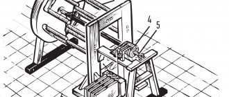
| Rice. 4. Stator and rotor of an asynchronous motor with a wound rotor: 1 - stator winding; 2 - body; 3 - stator core; 4 - box with terminals; 5 — rotor core; 6 — rotor winding; 7 -pin rings |
Smooth start of a wound rotor motor
The smooth acceleration system of an electric motor with a wound rotor operates automatically . The operator presses the “Start” button, then the automation does everything itself.
The main contactor connects the stator winding to three-phase voltage. The engine begins to rotate at the lowest possible speed, since resistors with the highest possible resistance are included in the rotor circuit.
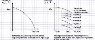
After a fixed delay generated by a time relay, the first contactor is turned on, shunting the first section of resistance in the rotor circuit. The rotation speed increases slightly. More time passes, the second time relay starts the next contactor. The next section of resistance is shunted, the current in the rotor circuit increases, and the rotation speed increases. And so on, until all resistance is completely eliminated from the rotor circuit. In this case, the electric motor reaches its rated speed.
Scheme of soft start of an asynchronous electric motor with a wound rotor
The number of acceleration stages is selected based on the launch severity conditions. Acceleration is not so smooth; the current in the stator increases in steps. When starting and transitioning to each subsequent stage, the electric motor still consumes starting current , albeit of a smaller value.
Electric motors, for acceleration of which liquid starters (or starters) . They use a liquid with high resistivity as a resistor. This is distilled water with a special salt dissolved in it. Reducing the resistance is achieved by reducing the distance between the electrodes placed in this liquid. The electrodes are driven by a small electric motor through a worm gear. Due to this, the resistance in the rotor circuit decreases and the electric motor accelerates smoothly.
Adjusting the speed of crane motors
If, during a smooth start of an electric motor with a wound rotor, the switching of resistances is controlled automatically, then on the crane this is controlled by the operator - the crane operator. To do this, controls are located in its cabin - controllers (on old cranes) or joysticks (on modern ones). They have two directions of movement: “forward-backward”, “left-right” or “up-down”, depending on the purpose of the controller (control of a bridge, trolley or lifting a load, respectively). In each direction, the control handle passes through a number of fixed positions. The further the position from the handle is from the midpoint at which the drive is turned off, the higher the rotation speed of the electric motor. And the faster the mechanism moves or the load rises (lowers).
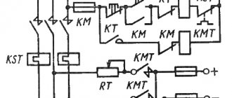
Typical crane motor control circuit
When you change the direction of movement of the control handle, the direction of rotation of the electric motor changes . This occurs by switching the phase rotation of the stator winding power supply. To do this, the two phases are swapped. This happens by applying voltage to the winding using reversible contactors, consisting of two elements: a “Forward” contactor and a “Backward” contactor.
Asynchronous motor
Among devices that convert electrical energy into mechanical energy, the undoubted leader is the three-phase asynchronous motor - a simple and reliable unit to operate. Due to its qualities, it is widely used in industry and other areas where mechanisms are used. The name of the engine is associated with the basic principle of its operation. In these devices, the stator magnetic field rotates at a frequency exceeding the rotor speed. The unit operates from an alternating current network.
Characteristics of an asynchronous motor
- Starting the engine with a load, connecting to the shaft due to the creation of a large torque. This ensures servicing of asynchronous motors with a phase element of any power.
- Possibility of constant rotation speed for large or small loads
- Automatic start regulation.
- Works even with voltage overload.
- Ease of use.
- Low cost.
- Reliability of use.
- The use of resistors increases the cost, and the operation of the motor becomes more complicated;
- Big sizes;
- The efficiency value is less than that of squirrel-cage rotors;
- Difficulty controlling rotation speed;
- Regular major repairs.
Where are they used?
Asynchronous motors are actively used in many industries and agriculture. They consume approximately 70% of all energy used to convert electricity into rotational or translational motion. Asynchronous motors have proven themselves to be the most effective as electric traction, without which many technological operations cannot be done.
Asynchronous motors have many positive qualities. The simple design allows for the production of the cheapest and most reliable devices. Minimum operating costs are ensured by the absence of a sliding current collection unit, which simultaneously increases the reliability of the unit.
This type of electric motor can be three-phase or single-phase, depending on the number of supply phases. If necessary and subject to certain conditions, a three-phase unit can be powered and operated from a single-phase network. These devices are used not only in industry, but also in domestic conditions, as well as in garden plots or home workshops. Single-phase motors power and rotate fans, washing machines, small machines, water pumps and power tools.
For normal operation of an asynchronous unit, it is necessary to choose the most rational control scheme. A three-phase motor will operate in single-phase mode, provided that the capacitors are correctly calculated, the type and cross-section of wires, protection and control equipment are selected.
Asynchronous motor device
The concept asynchronous means not coinciding in time, non-simultaneous. In this regard, the rotor of such a motor rotates at a frequency lower than the rotation frequency of the electromagnetic field of the stator.
Such a lag is called slip and is denoted by the symbol S in the formula used for calculations:
- S = (n1 – n2)/n1 – 100%, where n1 is the synchronous frequency of the stator magnetic field, and n2 is the shaft rotation frequency.
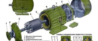
Structurally, a standard asynchronous electric motor includes the following elements and parts:
- Stator with windings. This function can also be performed by a frame, inside which a stator with windings is placed.
- Squirrel-cage rotor. If a phase one is used, it can be called an armature or a collector.
- Bearings of various types - rolling or sliding. On high-power engines, bearing caps with seals are installed in the front part.
- A metal or plastic cooling fan housed in a housing with slots for air supply.
- The cables are connected using a terminal box.
These structural elements may vary slightly depending on the modification of the electric motor.
As already noted, asynchronous motors are three-phase or single-phase. The first option, in turn, is available with a squirrel-cage or wound-wound rotor. The most widespread are three-phase asynchronous electric motors with a squirrel-cage rotor, so they should be considered in more detail.
The stator has a round shape and is assembled from special steel sheets insulated with each other. As a result, a core is structurally formed with grooves into which the windings are placed. For these purposes, a winding copper wire insulated with varnish is used. In powerful units, the windings are made in the form of a bus. When laying, they move between each other by 120 degrees. The connection is made according to a star or delta scheme.
The design of the squirrel-cage rotor itself is made in the form of a shaft with steel sheets placed on it. This set of sheets forms a core with grooves that are filled with molten aluminum. Spreading evenly over the grooves, the aluminum forms rods, the edges of which are closed by aluminum rings.
The phase rotor consists of a shaft with a core and three windings. At one end they are connected by a star, and at the other they are connected to slip rings, to which electric current is supplied using brushes. During startup, a large starting current of the asynchronous motor is generated. It can be reduced by adding a load rheostat to the phase windings.
Engine device
The main constants are the stator and rotor. The stator is a cylinder, the composition is sheets of electrical steel, a three-phase winding is laid in the cylinder. It consists of winding wire. Which are connected to each other in the form of a star or triangle depending on the voltage.
The rotor is the main rotating part of engines. Depending on its location, it can be external or internal. This element consists of steel sheets. The core slots are filled with aluminum, which has rods containing end rings. They can be brass or steel, each of them is insulated with a layer of varnish. A gap is formed between the three-phase stator and the rotor. Adjustment of the gap size from 0.30–0.34 mm in devices with low voltage, 1.0–1.6 mm in devices with high constant electrical voltage. The design is called a “squirrel cage”. For high-power motors, a copper core is used. The contactor starts operating and the engine starts.
There is an additional resistor in the winding circuit of the rotating part of the machine, which is attached using metal-graphite brushes. There are usually two brushes, located on the brush holder. In drives of cranes and centrifuges, a conical movable rotor is used to regulate the robot. Asynchronous motors with a wound rotor are indispensable for the technical requirements of a powerful starting torque. These can be mechanisms such as a crane, a mill, an elevator.
Scheme for switching an electrical circuit from star to delta
Principle of operation
The design and design features of an asynchronous motor also determine the operating principle of this unit. When voltage is applied to the stator winding, a magnetic field is formed in it. This voltage supply leads to changes in the magnetic flux and the entire magnetic field of the stator. The changed magnetic fluxes enter the rotor, drive it, after which it begins to rotate. In order for the stator and rotor to operate asynchronously, the voltage and flux values are required to be equal to the alternating current used as the power source.
The engine itself works as follows:
- The rotating magnetic field acts on a short-circuited winding specially adapted for rotation.
- The field crosses the conductors of the rotor winding, inducing an electromotive force in them.
- Under the influence of force, an electric current will begin to flow in the rotor conductors, interacting with the rotating magnetic field. This leads to the appearance of electromagnetic forces acting on the rotor winding.
- In total, the actions of the applied forces cause the appearance of a torque that causes the rotor to rotate in the direction of the magnetic field.
The magnitude of the induced emf depends on the frequency of the intersection of the conductors with a rotating magnetic field. That is, the higher the difference between n1 and n2, the greater the EMF value will be. The rotor will rotate at a frequency n2, which will always lag behind the synchronous frequency of the stator field n1. This difference between both frequencies will be the slip frequency ∆n= n1- n2. This inequality is a necessary condition for the appearance of electromagnetic rotating torque in an asynchronous motor. That’s why the unit is called that, since the rotor rotates asynchronously with the stator field.
Operating principle of an asynchronous motor
By applying voltage only to the stator winding, the asynchronous motor begins to operate. Interested to know how it works, why this happens? This is very simple if you understand how the induction process occurs when a magnetic field is induced in the rotor. For example, in DC machines, you have to separately create a magnetic field in the armature (rotor) not through induction, but through brushes.
When we apply voltage to the stator windings, an electric current begins to flow through them, which creates a magnetic field around the windings. Further, from many windings that are located on the stator magnetic circuit, a common magnetic field of the stator is formed. This magnetic field is characterized by a magnetic flux, the magnitude of which changes over time; in addition, the direction of the magnetic flux changes in space, or rather, it rotates. As a result, it turns out that the stator magnetic flux vector rotates like a spun sling with a stone.
In full accordance with Faraday's law of electromagnetic induction, in a rotor that has a short-circuited winding (short-circuited rotor). An induced electric current will flow in this rotor winding since the circuit is closed and it is in short circuit mode. This current, just like the supply current in the stator, will create a magnetic field. The motor rotor becomes a magnet inside the stator, which has a magnetic rotating field. Both magnetic fields from the stator and rotor will begin to interact, obeying the laws of physics.
Since the stator is motionless and its magnetic field rotates in space, and a current is induced in the rotor, which actually makes it a permanent magnet, the movable rotor begins to rotate because the magnetic field of the stator begins to push it, dragging it along with it. The rotor seems to mesh with the magnetic field of the stator. We can say that the rotor tends to rotate synchronously with the magnetic field of the stator, but this is unattainable for it, since at the moment of synchronization the magnetic fields cancel each other out, which leads to asynchronous operation. In other words, when an asynchronous motor operates, the rotor slides in the magnetic field of the stator.
Sliding can be either delayed or advanced. If there is a delay, then we have a motor mode of operation, when electrical energy is converted into mechanical energy; if sliding occurs with the rotor advancing, then we have a generator mode of operation, when mechanical energy is converted into electrical energy.
The torque generated on the rotor depends on the frequency of the alternating current supply to the stator, as well as on the magnitude of the supply voltage. By changing the frequency of the current and the magnitude of the voltage, you can influence the rotor torque and thereby control the operation of the asynchronous motor. This is true for both single-phase and three-phase asynchronous motors.
What is sliding
The concept of slip is the ratio of rotational speed to field frequency. This value of S is taken as a percentage of the rotation frequency of the magnetic field. In accordance with the formula discussed earlier, the rotor speed determined by sliding will be: n2 = n1 x (1 – S).
The rotor of an induction motor rotates in the same direction as its magnetic field. In turn, the direction of rotation of the field depends on the phase sequence of the three-phase network. It is possible to change the direction of rotation of the rotor by changing the direction of rotation of the field created by the stator. In this case, the order in which current pulses arrive to the individual windings changes. If necessary, clockwise or counterclockwise rotation can be specified.
An important point is the start of an asynchronous motor, during which the rotor winding intersects with a rotating magnetic field. As a result, a large EMF is induced, creating a high inrush current. This condition is compensated by a special load that reduces the rotor rotation speed.
Synchronous and asynchronous motor
Operation of an asynchronous motor in generator mode
Asynchronous motor with squirrel-cage rotor diagram
Generator from an asynchronous motor
Operating principle of a frequency converter for an asynchronous motor
Slip of an asynchronous motor. Rotor speed
A distinctive feature of an asynchronous motor is that the rotor speed n2 is less than the synchronous speed of the stator magnetic field n1.
This is explained by the fact that the EMF in the rotor winding rods is induced only when the rotation frequencies n21 are unequal . The rotation frequency of the stator field relative to the rotor is determined by the sliding frequency ns=n1-n2. The lag of the rotor from the rotating field of the stator is characterized by a relative value s called slip:
,
· where s is the slip of an asynchronous electric motor,
· n1 – rotation frequency of the stator magnetic field, rpm,
· n2 – rotor speed, rpm,
Let us consider the case when the rotor rotation frequency coincides with the rotation frequency of the stator magnetic field. In this case, the relative magnetic field of the rotor will be constant, thus no EMF, and therefore no current, will be created in the rotor rods. This means that the force acting on the rotor will be zero. This will slow down the rotor. After which an alternating magnetic field will again act on the rotor rods, thus the induced current and force will increase. In reality, the rotor of an asynchronous electric motor will never reach the rotation speed of the stator magnetic field. The rotor will rotate at a certain speed which is slightly less than the synchronous speed.
The slip of an asynchronous motor can vary in the range from 0 to 1, i.e. 0-100%. If s~0, then this corresponds to the idle mode, when the engine rotor experiences practically no counteracting torque; if s=1 - short circuit mode, in which the motor rotor is stationary (n2 = 0). Slip depends on the mechanical load on the motor shaft and increases with its growth.
The slip corresponding to the rated load of the motor is called rated slip. For low and medium power asynchronous motors, the rated slip varies from 8% to 2%.
Energy conversion
An asynchronous motor converts electrical energy supplied to the stator windings into mechanical energy (rotation of the rotor shaft). But the input and output power are not equal to each other since energy losses occur during conversion: friction, heating, eddy currents and hysteresis losses. This energy is dissipated as heat. Therefore, an asynchronous electric motor has a fan for cooling.
Asynchronous motor with wound rotor
An asynchronous motor with a wound rotor is a motor that can be controlled by adding additional resistances to the rotor circuit. Typically, such motors are used when starting with a load on the shaft, since increasing the resistance in the rotor circuit allows increasing the starting torque and reducing starting currents. In this way, an asynchronous motor with a wound rotor compares favorably with an induction motor with a squirrel-cage rotor.
The stator (3) is made in the same way as in a conventional asynchronous motor; it is a hollow cylinder made of sheets of electrical steel, in which a three-phase winding is laid.
The rotor (4), compared to the squirrel-cage rotor, is a more complex structure. It consists of a core in which a three-phase winding is laid, similar to a stator winding. Hence the name of the engine. If the motor is two-pole, then the rotor windings are offset geometrically relative to each other by 120. These windings are connected to three slip rings (2) located on the rotor shaft (5). The contact rings are made of brass or steel, and they are insulated from each other. With the help of several metal-graphite brushes (usually two), which are located on the brush holder (1) and pressed against the rings by springs, additional resistance is introduced into the circuit. The winding terminals are connected in a star configuration.
Additional resistance is introduced only when starting the engine. Moreover, they are usually served by a stepped rheostat, the resistance of which decreases with increasing engine speed. Thus, the engine is also started in steps. After acceleration has ended and the engine has reached its natural mechanical characteristics, the rotor winding is short-circuited. In order to preserve the brushes and reduce losses on them, in motors with a wound rotor there is a special device that lifts the brushes and closes the rings. Thus, it is also possible to increase the efficiency of the engine.
The additional resistance mainly makes it possible to start the engine under load; the engine cannot work with it for a long time, since the mechanical characteristics are too soft and engine operation on them is unstable.
In order to automate the starting of the engine, inductance is included in the rotor winding. At the moment of starting, the frequency of the current in the rotor is greatest, and therefore the inductive reactance is maximum. Then, as the engine accelerates, the frequency and resistance decrease, and the engine gradually begins to operate in normal mode.
Due to the complexity of its design, an asynchronous motor with a wound rotor has good starting and control characteristics. But for the same reason, its cost increases by approximately 1.5 compared to a conventional motor, in addition, the weight and dimensions increase and, as a rule, the reliability of the engine decreases.
Source: electroandi.ru
Design, principle of operation and connection diagram of an asynchronous motor with a wound rotor
The wound-rotor asynchronous motor has a very wide service area. IM (asynchronous motor) is more often used in controlling high-power motors. Maintenance and control of drives of mills, machine tools, pumps, cranes, smoke exhausters, crushers. An asynchronous motor with a massive rotor makes it possible to connect a variety of technical mechanisms.
- Characteristics of an asynchronous motor
- Connection diagram
- Engine device
- Principle of operation
- Calculation of the number of repetitions
- Rheostat start
- Repair and fault characteristics
general information
To understand how an asynchronous motor with a wound rotor works, you need to carefully study the features of its start-up. When the installation is started, its rotor moves in parallel from a state of rest to slow and uniform rotation. In this case, the system balances the moment of resistance forces through its own shaft.
During startup, increased consumption of energy resources begins, which is associated with overcoming the braking torque and compensating for losses inside the power plant. Often the parameters of the initial starting torque are far from the required ones, so the asynchronous motor is not able to switch to full operation mode. In this case, acceleration is suspended, and constant exposure to excessive current leads to overheating of the internal components of the installation.
For this reason, the frequency of engine starts is limited to several starts. If the unit was operating from a low-power electrical network, then this phenomenon could reduce the overall voltage and disrupt the operation of other devices connected to this line.
The presence of starting resistors in the rotor circuit reduces the electric current, but at the same time raises the initial starting torque until it reaches the peak level. Starting the power plant can be easy, normal or difficult.
Depending on this factor, you can determine the optimal resistance parameters of the resistors.
After a successful launch, it remains to maintain a stable torque during the rotor acceleration stage, which will shorten the duration of the transition from a quiet state to the rotation stage and reduce the likelihood of heating. To do this, it is necessary to reduce the resistance values of the resistors.
The switching of different resistors occurs due to the connection of the acceleration contactors in series order. The engine can only be disconnected from the electrical network when the rotor circuit is short-circuited. If this requirement is ignored, there will be a risk of significant overvoltage in the stator winding phases.
Specifications
There are established requirements that guarantee high-quality operation of asynchronous motors with a wound rotor. The basic parameters and characteristics of the system depend on them, including:
- Dimensions and power of the installation comply with technical regulations.
- Protection from external influences. Its degree is determined by the environmental conditions in which the machine will be located. The fact is that some installations are designed to work indoors, while others can function outdoors. In addition, the units available on the market differ in climatic conditions. For example, there are engines that can withstand extreme cold or, conversely, extreme heat. Depending on the conditions of use, they have characteristic performance and protection.
- Degree of insulation. Asynchronous motors with a wound rotor must be resistant to high temperatures and possible heating of internal mechanisms. To prevent ignition, they are protected with special insulating layers.
- Compliance with established standards and operating modes.
- The presence of a powerful cooling system that matches the operating mode of the engine.
- Noise level during startup at idle speed. It is equivalent to second class or lower.
Device and design
If you want to buy an asynchronous electric motor with a wound rotor, you need to have a good understanding of its structure and design features. First of all, you need to know that the main parts of the installation include the stator , which is stationary, and the rotor, which is a rotating mechanism inside the stator. There is an air gap between both elements, and their surface is covered with a special winding.
The stator winding is connected to an electrical network with alternating voltage, which is transmitted to the rotor winding. The interaction of nodes is determined by magnetic flux.
As for the stator housing, the motor housing is used as it, inside of which there is a pressed core. The latter contains the winding conductors, protected from short circuits by insulation. The core winding consists of several sections enclosed in coils.
The rotor has a shaft and a core made of assembled plates. The last element is created on the basis of high-tech steel and has symmetrical grooves with conductors. During operation, the rotor shaft transmits torque to the installation drive. Depending on the type of rotor, there are two types of engines:
- With squirrel-cage rotor.
- With wound rotor.
The first type of rotors contains aluminum rods, which are located inside the core and closed at the ends with rings. They are also called "squirrel wheels". Typically, the installation grooves are treated with aluminum, which increases their strength.
Device
To work with asynchronous motors and fully understand the principles of operation of such machines, it is necessary to familiarize yourself with the features of their design:
- The main parts of the unit design are the stator, which is stationary, and the rotating rotor, which is located inside it.
- An air gap separates both elements from each other.
- Both the stator and the rotor have a special winding.
- The stator winding is connected to an AC power supply.
- The rotor winding is inherently secondary, since it is not connected to the network, and the transfer of the necessary energy for it is carried out directly by the stator. This process occurs due to the creation of magnetic flux.
- The stator housing and the motor housing are one element that has a pressed core in its structure.
- in the grooves of the core . A special electrical varnish ensures reliable insulation of these objects from each other.
- The core winding is specially divided into sections that are connected into coils.
- The coils make up the phases of the motor itself , to which the phase from the supply network is connected.
- The rotor consists of a shaft and a core.
- The rotor core is created from assembled plates, which are made from a special type of electrical steel. On its surface there are symmetrical grooves, inside of which the winding conductors are located.
- , the rotor shaft performs the functions of transmitting torque directly to the drive mechanism of the machine.
- The rotors have their own classification; the short-circuited version has rods made of aluminum in its design. They are located inside the core, and at the ends they are closed with special rings. This system is called the squirrel wheel. In machines with the highest power, the grooves are additionally filled with aluminum, which increases the strength of the structure.
- Instead of a squirrel cage rotor, the design may have a phase type. The number of coils shifted at a certain angle relative to each other in such a system depends on the number of paired poles. In this case, the rotor pairs of poles are always equal to the number of similar pairs in the stator. The rotor winding is connected in a special way and resembles a star in shape, and its rays are output to the contacts of the slip rings, which are connected using a brush-type mechanism and a starting rheostat.
Principle of operation
Having studied the device of an IM with a wound rotor and its startup, we can begin to examine in more detail the operation of such an installation. It can be divided into several points:
- The stator with a triple winding is supplied with three-phase voltage from an alternating current electrical network.
- Then the formation of a magnetic field begins, which leads to rotation of the rotor. As the rotational movements accelerate, the rotor speed increases significantly.
- Upon reaching certain indicators, individual field lines of both nodes intersect, which causes the appearance of an electromotive force. It acts on the rotor winding, due to which an electric current is formed in it.
- At a certain point in time, interaction begins between the stator magnetic field and the current in the rotor, generating torque. It is due to this that the asynchronous motor operates.
Speed control of asynchronous motors
To regulate the rotation speed of asynchronous electric motors and control their operating modes, the following methods exist:
- Frequency - when the frequency of the current in the electrical network changes, the rotation speed of the electric motor changes. For this method, a device called a frequency converter is used;
- Rheostat - when the resistance of the rheostat in the rotor changes, the rotation speed changes. This method increases the starting torque and critical slip;
- Pulse is a control method in which a special type of voltage is supplied to the motor.
- Switching the windings during operation of the electric motor from a star circuit to a delta circuit, which reduces starting currents;
- Control by changing pole pairs for squirrel-cage rotors;
- Connecting inductive reactance for wound-rotor motors.
With the development of electronic systems, the control of various asynchronous electric motors is becoming more efficient and accurate. Such engines are used everywhere in the world, the variety of tasks performed by such mechanisms is growing every day, and the need for them is not decreasing.
Advantages and disadvantages
Recently, asynchronous units have become very popular. It is associated with a lot of advantages that they have. Among them:
- High values at initial torque.
- The ability to accept any mechanical overload without significantly changing the efficiency or disrupting the stable operation of the installation. Even if various overloads occur in the system, the unit continues to operate at the set speed and practically does not deviate from the basic mode.
- Reduced starting current. Unlike other asynchronous models, for example, with a squirrel-cage rotor, these motors have relatively low starting currents.
- Possibility of full automation of work.
- Simplicity of design.
- Simple launch scheme.
- Relatively low price.
- No need for complex and expensive maintenance.
In addition to many advantages, engines of this type also have disadvantages. The key disadvantages include the rather large dimensions, which make installation and further operation of the system more complicated, as well as reduced efficiency compared to many analogues.
According to the latter indicator, devices with squirrel-cage rotors are more productive.
Areas of application
Nowadays, many industrial motors are asynchronous. Their popularity is due to the above advantages and availability. The scope of application of such units is very wide, so they are actively used for the operation of automated devices from the telemechanical sector, household and medical equipment and sound recording installations. An asynchronous motor is a useful invention of the present time, which simplifies human life and provides good efficiency with minimal energy consumption.
Source: 220v.guru
Design and principle of operation of three-phase electric motors
This article addresses the following issues:
- Three-phase electric motor design.
- The operating principle of a three-phase electric motor.
Electric motor design 380 V
The most widespread among three-phase electric motors in industry, agriculture and everyday life are asynchronous electric motors with a squirrel-cage rotor due to their simplicity of design, reliability and low cost. Therefore, using the example of just such an electric motor, we will consider their structure and operating principle.
An asynchronous electric motor consists of two main parts: a stator and a rotor.
The stator is the stationary part of the electric motor. It consists of the following elements:
- frame (body) which, as a rule, is ribbed for better cooling, because During operation, the stator core and windings heat up. The frame also has legs for mounting the electric motor.
stator core - assembled from separate sheets of electrical steel to reduce losses due to eddy currents (Foucault currents) and has a gear shape (grooves) and has the following form:
- stator windings are made of copper wires that are laid in the grooves of the core, the ends of the windings for connection to the electrical network are brought out into the terminal box.
The rotor is the rotating part of an electric motor. The rotor consists of the following elements:
- shaft - made of steel and used to transmit mechanical energy to the working mechanism.
- rotor core - mounted on the shaft, just like the stator core, made of separate sheets of electrical steel
- rotor winding - usually has a short-circuited design; the short-circuited rotor winding is often called a “squirrel wheel” because of its external similarity. The short-circuited rotor winding has the following form:
The rotor is held in the center of the stator by bearing shields.
Three-phase squirrel-cage asynchronous motor
Construction of an asynchronous electric motor
A three-phase asynchronous electric motor, like any electric motor, consists of two main parts - a stator and a rotor. The stator is the stationary part, the rotor is the rotating part. The rotor is placed inside the stator. There is a small distance between the rotor and stator, called an air gap, usually 0.5-2 mm.
Stator
consists of a body and a core with a winding. The stator core is assembled from thin sheet technical steel, usually 0.5 mm thick, coated with insulating varnish. The laminated core design contributes to a significant reduction in eddy currents arising during the process of magnetization reversal of the core by a rotating magnetic field. The stator windings are located in the slots of the core.
Rotor
consists of a core with a short-circuited winding and a shaft. The rotor core also has a laminated design. In this case, the rotor sheets are not varnished, since the current has a low frequency and the oxide film is sufficient to limit eddy currents.
Principle of operation. Rotating magnetic field
The operating principle of a three-phase asynchronous electric motor is based on the ability of a three-phase winding to create a rotating magnetic field when connected to a three-phase current network.
A rotating magnetic field is the basic concept of electric motors and generators.
The rotation frequency of this field, or the synchronous rotation frequency, is directly proportional to the frequency of the alternating current f1 and inversely proportional to the number of pole pairs p of the three-phase winding.
,
- where n1 is the rotation frequency of the stator magnetic field, rpm,
- f1 – alternating current frequency, Hz,
- p – number of pole pairs
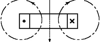
Rotating magnetic field concept
To understand the rotating magnetic field phenomenon better, consider a simplified three-phase winding with three turns. Current flowing through a conductor creates a magnetic field around it. The figure below shows the field created by three-phase alternating current at a specific point in time
The components of alternating current will change over time, causing the magnetic field they create to change. In this case, the resulting magnetic field of the three-phase winding will take different orientations, while maintaining the same amplitude.
The effect of a rotating magnetic field on a closed loop
Now let's place a closed conductor inside a rotating magnetic field. According to the law of electromagnetic induction, a changing magnetic field will give rise to an electromotive force (EMF) in the conductor. In turn, the EMF will cause a current in the conductor. Thus, in a magnetic field there will be a closed conductor with a current, on which, according to Ampere’s law, a force will act, as a result of which the circuit will begin to rotate.