Subscribe to the newsletter
Production processes involving the operation of equipment equipped with AC or DC electric motors require periodic shutdowns.
However, after disconnecting the supply voltage from the electric motors, their rotors continue to rotate by inertia and stop only after a certain period of time. This stopping of the electric motor is called freewheeling. For electric motors that operate with frequent starts and stops, free coasting is not suitable. To reduce the time required to completely stop rotor rotation, forced braking is applied. Electric motor braking methods are divided into mechanical and electrical.
Mechanical braking
Stopping engines with this method of braking is carried out thanks to special pads on the brake pulley. After turning off the supply voltage, the brake pads are pressed against the pulley under the influence of springs. As a result of the friction between the pads and the pulley, the kinetic energy of the rotating shaft is converted into thermal energy, which leads to its complete stop. After applying voltage, the electromagnet (YB) releases the brake pads, and operation of the electric motor continues in normal mode.
Depending on the electrical braking circuit, the kinetic energy of the rotating rotor can be transferred to the network or to a battery of capacitors, and also converted into heat, which is absorbed by the windings of the electric motor or special rheostats.
Dynamic motor braking
This stopping circuit is suitable for three-phase electric motors with both squirrel cage and wound rotor types.
Dynamic braking of an electric motor with a squirrel-cage rotor is carried out by disconnecting the stator windings from the three-phase alternating current supply network and switching two of them through a system of contactors and relays to a source of rectified direct voltage.
The stator windings, after applying constant voltage to them, generate a stationary magnetic field, under the influence of which in a short-circuited “squirrel cage”
rotating rotor, an electric current begins to be induced, causing the appearance of a tomosive moment. The direction of this moment is opposite to the direction of rotation of the stopping shaft. After stopping the engine, the supply of direct voltage to the stator windings is stopped.
In motors with a wound rotor, the amount of braking torque can be adjusted using additional resistances, which are used as starting resistors.
Back braking
Braking of an asynchronous electric motor using the back-to-back method is carried out by reversing the motor without disconnecting from the supply network.
Braking control is performed by the speed control relay. In operating mode, the relay contacts are closed. After pressing the “STOP” button (SBC), the group of contactors switches two phases, changing the order of their alternation. As a result, the stator's magnetic field begins to rotate in the opposite direction, which causes the rotor to slow down. When the rotation speed becomes close to zero, the speed control relay opens its contacts and the supply voltage is stopped.
Capacitor braking of electric motors
This method, also called self-excited braking, is applicable only to electric motors with a squirrel-cage rotor.
After the supply voltage is stopped, the electric motor rotor continues to rotate by inertia and generates an electric current in the stator windings, which first charges the capacitor bank, and after accumulating the rated charge returns to the windings. This leads to the occurrence of a braking torque, the magnitude of which depends on the capacity of the capacitor banks connected to each phase in a star or delta configuration. Self-excited braking is used on engines with a large number of starts and stops, since the amount of energy loss in the engines with such a stopping scheme is minimal.
Regenerative braking
Regenerative or otherwise regenerative braking of asynchronous electric motors is used in practice as preliminary braking, as well as when lowering loads with cranes of all types or passenger and freight elevator cabins.
Braking of an asynchronous electric motor in regenerative mode occurs when the rated rotor speed exceeds its synchronous frequency. The engine begins to generate electrical energy and send it to the power supply network, resulting in the creation of a braking torque. This stopping method is used for multi-speed motors by gradually switching from a higher rotor speed to a lower one. Thus, at a certain moment, the speed rotating under the influence of the inertia of the shaft will be greater than the synchronous frequency corresponding to the connected number of stator poles. In addition, a regenerative braking circuit is used for motors connected to frequency converters. To do this, it is enough to reduce the frequency of the supply voltage.
Stopping DC motors (DCM)
Braking of DC electric motors is carried out by counter-switching and in a dynamic way.
Dynamic braking
This braking circuit is used for motors with independent excitation.
After pressing the “Stop” button (SB1), the armature windings are disconnected from the supply network and reconnected to the braking resistor. In the windings of the armature, rotating by inertia in a stationary magnetic field, a direct current is induced, which, passing through the winding wires of the resistor, is converted into thermal energy.
Back-up braking The back-up method is based on changing the polarity of the voltage connected to the windings of the inductor or motor armature. This results in a change in the polarity of the magnetic flux or the direction of the current induced in the armature. Thus, the direction of the torque is reversed, which causes a braking effect. The speed of rotation of the armature is controlled by a speed relay, which cuts off power to the armature when it approaches zero.
Source
Methods and schemes for braking electric motors
Electric motor braking is used if it is necessary to reduce the free run time and fix the mechanism in a specific position.
There are several types of forced device stop. These are mechanical, electrical and combined. The mechanical device is a brake pulley mounted on a shaft with pads. After the device is turned off, the pads are pressed against the pulley. Due to friction, kinetic energy is converted into thermal energy, i.e. the braking process occurs. Other methods and circuits for braking an electric motor will be discussed later in the article. Production processes involving the operation of equipment equipped with AC or DC electric motors require periodic shutdowns. However, after disconnecting the supply voltage from the electric motors, their rotors continue to rotate by inertia and stop only after a certain period of time. This stopping of the electric motor is called freewheeling.
For electric motors that operate with frequent starts and stops, free coasting is not suitable. To reduce the time required to completely stop rotor rotation, forced braking is applied. Electric motor braking methods are divided into mechanical and electrical.
Mechanical braking
Stopping engines with this method of braking is carried out thanks to special pads on the brake pulley. After turning off the supply voltage, the brake pads are pressed against the pulley under the influence of springs. As a result of the friction between the pads and the pulley, the kinetic energy of the rotating shaft is converted into thermal energy, which leads to its complete stop. After applying voltage, the electromagnet (YB) releases the brake pads, and operation of the electric motor continues in normal mode.
Depending on the electrical braking circuit, the kinetic energy of the rotating rotor can be transferred to the network or to a battery of capacitors, and also converted into heat, which is absorbed by the windings of the electric motor or special rheostats.
Dynamic motor braking
This stopping circuit is suitable for three-phase electric motors with both squirrel cage and wound rotor types.
Dynamic braking of an electric motor with a squirrel-cage rotor is carried out by disconnecting the stator windings from the three-phase alternating current supply network and switching two of them through a system of contactors and relays to a source of rectified direct voltage.
The stator windings, after applying constant voltage to them, generate a stationary magnetic field, under the influence of which in a short-circuited “squirrel cage”
rotating rotor, an electric current begins to be induced, causing the appearance of a tomosive moment. The direction of this moment is opposite to the direction of rotation of the stopping shaft. After stopping the engine, the supply of direct voltage to the stator windings is stopped.
In motors with a wound rotor, the amount of braking torque can be adjusted using additional resistances, which are used as starting resistors.
Back braking
Braking of an asynchronous electric motor using the back-to-back method is carried out by reversing the motor without disconnecting from the supply network.
Braking control is performed by the speed control relay. In operating mode, the relay contacts are closed. After pressing the “STOP” button (SBC), the group of contactors switches two phases, changing the order of their alternation. As a result, the stator's magnetic field begins to rotate in the opposite direction, which causes the rotor to slow down. When the rotation speed becomes close to zero, the speed control relay opens its contacts and the supply voltage is stopped.
DC Motor Braking Circuits
When stopping and reversing direct current motors (DCM), electrical (dynamic and counter-switching) and mechanical braking are used.
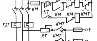
In dynamic braking, the circuit disconnects the armature winding from the mains and connects it to a braking resistor with one or more stages. Dynamic braking is controlled with time setting or speed control. To control the torque of the DBR with setting the time in the dynamic braking mode, the circuit node shown in Fig. is used. 1, a, designed to control the braking of a DFC with independent excitation with one stage of braking resistor R2.
Rice. 1. A circuit that implements one-stage (a) and three-stage (b) dynamic braking of a DC motor with time control and a starting diagram of three-stage braking (c).
The command to switch the DBT to dynamic braking mode in the above diagram is supplied from the SB1 button. In this case, the linear contactor KM1 disconnects the motor armature from the mains voltage, and the brake contactor KM2 connects a braking resistor to it. The command to count the time of the dynamic braking process for the KT braking relay is given to the linear contactors KM1, which performs the previous operation in the circuit before the start of dynamic braking. An electromagnetic DC time relay is used as a braking relay.
The circuit can be used to control DFCs with independent excitation and DFCs with series excitation, but in the latter case - with current reversal in the series excitation winding.
Regenerative braking of DC motor
This type of braking is used if the switched on electric motor rotates at a speed significantly exceeding the permissible idle speed. During reproductive braking, the electric motor also starts working as a generator and supplies electrical energy to the network.
The braking torque simultaneously occurs on the shaft. The mode is used in the drives of lifting mechanisms when the load is lowered. It is also permissible to use regenerative braking of the electric motor during speed control. This method is distinguished by a high degree of efficiency, since the electricity is returned to the network.
Braking DC motors
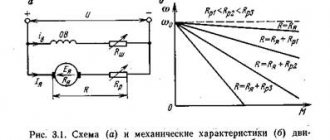
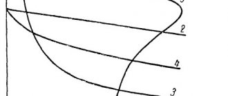
To quickly brake the engine, it is switched to a mode in which the electromagnetic torque changes direction. There are three methods of braking: 1) dynamic; 2) generator (regenerative); 3) anti-switching.
During dynamic braking, the armature is disconnected from the supply voltage and connected to the rheostat R
t (Fig.
a
).
From the equation for the armature chain 0 = E
+ (
R
I +
R
t)
I
I it follows that the current
I
I, and therefore the moment
M
, change direction (Fig.,
b
).
Since the frequency n
cannot change abruptly, at the moment of switching the operating point from
a
1 goes horizontally to
a
2 and then, slowing down along an inclined straight line, to the stopping point 0.
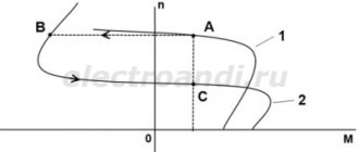
Regenerative braking occurs when condition E
>
U
.
From the equation U
=
E
+
I
I
R
I it follows that in this case
I
I, and therefore
M
, become negative, which can be observed when the engine lowers a load or a tram moves downhill.
The armature can pick up a frequency n
>
n
.
In Fig. 3.82, in
this corresponds to the movement of the operating point from position
a
1, through point
n
to
a
2, i.e., the transition of the machine from the motor mode (
M
> 0) to the generator mode (
M
Your opinion is important to us! Was the published material useful? Yes | No
Source