Direct start
Of all DC electric motors, the main gradation when choosing a method for starting them should take into account the power of the device.
In general, there are three types of launch:
- low power;
- average;
- high power.
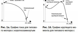
For direct starting, only low-power electric motors that consume up to 1 kW of electricity in the network are suitable. When starting the electric motor directly, all voltage is immediately applied to the working winding. This causes the occurrence of a maximum starting current due to the lack of natural compensation due to the counter EMF.
From a physical point of view, the situation in the rotor windings will look like this: at the moment the voltage is applied, the current strength in the windings is zero, so its value will be determined by the formula:
U is the rated voltage applied to the terminals, Rext is the coil resistance.
At this moment, the current load of the DC motor is maximum; it may differ from the nominal value by 1.5 - 2.5 times. After this, the flow of current causes the generation of a counter EMF, which compensates for the starting load until the rated power is set, then the current becomes:
In powerful devices, the resistance of the armature windings can be 1 or 0.5 Ohms, due to which the current when starting the electric motor can reach 200 - 500 A, which will be 10 - 50 times higher than the permissible values. This, in turn, can lead to thermal tempering of the metal, deformation of the conductors, and destruction of the rings or sliding contact brushes. Therefore, medium and high power DC motors must be put into operation by rheostat starting or by supplying a deliberately reduced voltage; direct starting is extremely dangerous for them.
How does a DC motor start?
Starting a DC motor has a number of distinctive features.
This is explained by the large value of the starting current, which must first be limited.
If this is not done, the internal circuit of the armature winding may be damaged.
There are several starting methods: direct, rheostatic and the method of smoothly increasing the supply voltage.
Starting with a starting rheostat
In this case, a variable resistance is introduced into the circuit, which at the initial stage ensures a reduction in the current load until the rotation of the rotor reaches the set speed. As the amperage stabilizes to a standard value in the rheostat, the resistance decreases from the maximum value to the minimum.
The calculation of the electrical quantity in this case will be made according to the formula:
In laboratory conditions, the load can be reduced manually - by moving the rheostat slider. However, this method is not widely used in industry, since the process is not consistent with current values. Therefore, adjustment by current, by EMF or by time is used, in the first case, the measurement of the value in the excitation windings is used, in the second, a time delay is applied to each stage.
Both methods are used to start electric motors:
- with sequential;
- with parallel excitation;
- with independent excitation.
Starting a DPT with parallel excitation
This start of the electric motor is carried out by turning on both the excitation winding and the armature to the power supply voltage; they are located in parallel relative to each other. That is, each of the windings of a DC electric motor is under the same potential difference. This starting method provides the hard operating mode used in machine tools. The current load in the auxiliary winding at start-up has a comparatively lower current than the stator or rotor windings.
To control the starting characteristics, resistances are introduced into both circuits:
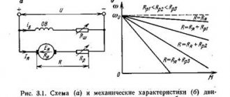
Fig. 1. Starting a parallel-excited DC motor
At the initial stage of shaft rotation, the rheostat positions reduce the load on the electric motor, and then they are brought back to the zero resistance position. During long starts, automation and combination of several stages of starting rheostats or individual resistors are performed; an example of such a connection circuit is shown in the figure below:
Methods of starting DC motors of parallel and series excitation.
For DC motors can be applied.
Direct start. The armature winding is connected to the network .
Starting is used for low power engines.
I
p = (4 ÷ 6)
I
nom.
Transient process of changing rotation speed n
and armature current
ia
is determined by the motor load and
T
m.
At Tm > 4Ta
aperiodic process of changing
ia
and
n
.
First, the current ia
increases (Fig.)
ia = I
start (1- e-
t
/
Ta
).
after time t
h the motor armature rotates and
n
increases and the EMF arising in the armature winding tends to reduce the current
ia
.
Delay time t
z =
Ta ln
[
I
start /(
I
start -
I
n )].
In reality, time tз
somewhat more due to the braking effect of eddy currents arising in massive parts of the machine’s magnetic circuit.
Maximum armature current value
I
max = [-
U
/(
p
2
La
)](
p
2 /
p
1 )
p
1/(
p
1 -
p
2).
The dotted line shows how the current ia
if the armature cannot rotate.
In Fig. Curves are plotted based on n
=
n
n(1 - e-
t
/
T
m);
ia =
(
I
start-
I
n) e-
t
/
T
m
+ I
n dependencies
n
and
ia
.
Transition time at start-up (3 ÷ 4) Tm
.
During this time, the rotation frequency n =
(0.95 -0.98) from the steady-state value, and the armature current
Ia
approaches the steady-state value.
Start by smoothly increasing the supply voltage . With rheostat starting, significant energy losses occur in the starting rheostat. This can be eliminated if the engine is started by gradually increasing the voltage supplied to its winding, but it is necessary to have a separate DC source with adjustable voltage.
Rheostat start. At the initial moment of start-up at n = 0
current
I
p
= U/(ΣRа + R
p
)
.
The maximum R
p is selected so that for machines of high and medium power
I
p = (1.4 ÷ 1.8)
I
nom, and for low power machines
I
p = (2 ÷ 2.5)
I
nom.
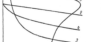
(first picture) motor with parallel excitation. Starting is carried out according to the rheostatic characteristic 6, the engine develops a maximum starting torque M
pmah.
The adjusting rheostat R
RV is output so that the current
I
V and F are maximum.
With increasing rotation speed, the EMF increases and the armature current I
a =
(U - E)/(ΣRa + R
p
)
.
At M
pmin, part of the resistance of the starting rheostat is removed and the torque increases again to
M
pmax, moves to curve
5
and accelerates to
M
p
min
. By reducing the resistance of the starting rheostat, the engine is accelerated along curves
6, 5, 4, 3
and
2
to natural
1
.
M
p.sr = 0.5 (
M
pmax +
M
pmin) = const the engine accelerates with some constant acceleration.
A motor with sequential excitation is started in the same way. The number of steps depends on the rigidity of the natural characteristic.
When outputting individual stages of the starting rheostat, the armature current Ia
reaches a certain maximum value, then decreases to a minimum.
With a change in the armature current, the electromagnetic moment M
.
M
din =
M - Mn
, ensures acceleration of the engine to a steady rotation speed.
3. simplified method for determining the effective number of electrical receivers
The effective number of electrical receivers is understood as such a number of receivers, equal in power and homogeneous in operating mode, which determines the same value of the calculated maximum as a group of receivers of different power and operating mode.
Effective number of electrical receivers
Based on the value of ne and the utilization factor, the maximum coefficient of CM and the half-hour maximum active load are determined
With the same power of electrical receivers,
with the same or slightly different powers of the electrical receivers of the group, it is recommended to determine the CM based on the actual number of electrical receivers.
average utilization factor:
The method of the effective number of electrical receivers is applicable for any groups of electrical receivers, including for electrical receivers of intermittent operation. In the latter case, the installed power Ru is reduced to PV = 100%, i.e. to a long-term operating mode.
The method of the effective number of power receivers is better than other methods in that the maximum coefficient, which is a function of the number of power receivers, is involved in determining the load. To calculate the reactive component of the load Q30 from the found value of P30, it is necessary to determine tanφ.
A simplified method for determining pe is used depending on the relative value of the effective number of electrical receivers p'e = ne/n.
This number is found using reference tables depending on:
where n1 is the number of power receivers, each of which has a power of at least half the power of the most powerful power receiver, ΣРпг1 is the sum of the installed capacities of these power receivers, n is the number of all power receivers, ΣPу is the sum of the installed capacities of all power receivers.
48 ticket
1. The concept of the main electrical connection diagram. Main factors and requirements when choosing schemes
The main electrical connection diagram of a power plant is a set of main electrical equipment, busbars, switching and other primary equipment with all connections made between them in kind.
The choice of the main circuit is decisive when designing the electrical part of the substation; it determines the complete composition of the elements and the connections between them. The main diagram is the starting point for drawing up schematic diagrams of electrical connections, auxiliary circuit diagrams, and secondary connection diagrams.
The main diagram shows all the elements of the installation in a single-line design in the disconnected position.
In operating conditions, simplified operating diagrams are used, which indicate the main equipment.
When designing, before developing the main circuit, a block diagram of power delivery is drawn up. They serve to develop more detailed and complete circuit diagrams.
When choosing electrical installation diagrams, the following should be taken into account:
the significance and role of a power plant or substation for the power system.
Start by changing the supply voltage
One of the options for reducing the current load when starting an electric motor is to reduce the supply rating using a constant voltage generator or a controlled rectifier.
From a physical point of view, installing a rheostat provides the same effect, but as the power of the electric motor increases, the constant current load also increases, and losses on the rheostats increase significantly. Therefore, DC voltage reduction is performed by a separate microcircuit-based device, an example of which is shown in the figure below:
Rice. 5. Starting circuit with changing supply voltage
Source
Starting DC motors
Publication date: March 04, 2013. Category: Articles.
When starting the engine, it is necessary: 1) to ensure the proper starting torque and conditions to achieve the required rotation speed; 2) prevent the occurrence of excessive starting current, which is dangerous for the engine. There are three possible ways to start the engine: 1) direct start, when the armature circuit is connected directly to the network at its full voltage; 2) starting using a starting rheostat or starting resistances connected in series to the armature circuit; 3) starting at low armature circuit voltage.
tickets_EM / 20. Methods of starting a DC motor
20. Methods of starting a DC motor.
There are three possible ways to start the engine:
1) direct start, when the armature circuit is connected directly to the network at its full voltage;
2) starting using a starting rheostat or starting resistances connected in series to the armature circuit;
3) starting at low armature circuit voltage.
Direct starting is used only for engines with a power of up to several hundred watts, for which Ra is relatively large and therefore, when starting, the starting process lasts no more than 1-2 seconds.
The most common is starting using a starting rheostat or starting resistances
Methods for starting a DC motor
1. Direct start
— the armature winding is connected directly to the network.
The motor armature current is determined by the formula. (4.1) If we assume that during direct starting the values of the supply voltage U and the resistance of the armature winding R i
then
the armature current depends on the back EMF
E. At the initial moment of starting the armature, the motor is stationary (
=0) and
E = 0
. Therefore, when connected to the network, a starting current appears in the winding.
(4.2) Usually the resistance R I
is small, especially for high-power motors, so the value of the starting current reaches 20 times the rated current of the motor. Unacceptably large values of 10 This creates the danger of breaking the machine shaft and strong sparking appears under the commutator brushes.
For this reason, such a start is used only for low-power engines, for which R i
is relatively large.
2)Rheostat start
— a starting rheostat is included in the armature circuit to limit the current.
At the initial moment of start-up at =0
and
R p =max,
the armature current will be equal to
. (4.3) The maximum value of Rп is selected so that for machines of high and medium power the armature current at start-up is , and for low-power machines . Let's consider the process of rheostatic starting using the example of a motor with parallel excitation (Fig. 4.1). At the initial moment, the start-up is carried out according to rheostatic characteristic 4, corresponding to the maximum resistance value R p
, while the engine develops a maximum starting torque
M pmax
. The control rheostat
R r
is set so that
I in
and
Ф
are maximum.
As the engine accelerates, the engine torque decreases, since as the rotor rotation speed increases, the EMF E
, and as a result, the armature current, which determines its value, decreases.
When a certain value M pmin
part of the resistance
R p
is removed, as a result of which the torque again increases to
M pmax
, the engine switches to operation according to rheostatic characteristic 3 and accelerates to the value
M pmin
. Thus, gradually reducing the resistance of the starting rheostat, the engine is accelerated along individual segments of the rheostatic characteristic until it reaches natural characteristic 1. The average starting torque is determined from the expression. (4.4) the engine accelerates with some constant acceleration.
A similar start is possible for series-excited motors. The number of starting stages depends on the rigidity of the natural characteristic and the requirements for smooth starting. Starting rheostats are designed for short-term operation under current.
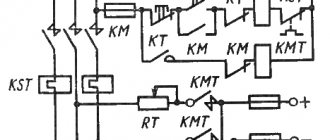
In real devices, start-up is automatic. The microcontroller, according to a given algorithm, controls the switching elements (relay control), turning off sections of the starting rheostat and practically implementing the process described above.
The control algorithm can be constructed using three basic principles:
1) EMF principle
2) Current principle
3) The principle of time.
The idea of implementing these principles can be explained using a starting circuit based on electromagnetic relays (which was practically used before the widespread introduction of microprocessor control systems) Figure 4.3. A series of relays are connected in parallel to the armature of the machine, which, with an increase in the rotation speed, and therefore the EMF, are sequentially activated and, with their contacts, remove the starting rheostat sections from operation, gradually reducing the resistance of the armature circuit.
When using the current principle, series-connected current relays are used, which give a command through their normally closed contacts to sequentially switch on the corresponding Ki contactors when the current drops to a given level.
The time principle involves the use of time relays, which, through calculated time settings, give a command to bypass the rheostat sections.
4)Start by smoothly increasing the supply voltage -
starting is carried out from a separate regulated power source. It is used for high-power engines, where it is impractical to use bulky rheostats due to significant energy losses.
3
Methods of starting DC motors.
2015-09-06 6727
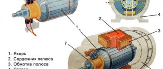
Energy diagram of a direct current generator of independent excitation.
Independent excitation generators are divided into generators with electromagnetic excitation, in which the excitation winding is powered by direct current from an external source (battery, auxiliary generator or DC exciter, AC rectifier), and magnetoelectric generators with poles in the form of permanent magnets. Generators of the latter type are manufactured only for low power.
Methods of starting DC motors.
There are three ways to start DC motors: direct starting, starting with a starting rheostat, and starting from a controlled voltage source.
Direct start from mains
Sometimes used for motors with power up to 1
kW
, the starting current of which does not exceed.
At the initial moment of direct starting at and the starting current is determined by the network voltage and the internal resistance of the armature. In machines of medium and high power, the resistance is small, so the starting current can reach . Such currents are unacceptable under switching conditions and can cause a “circular fire” on the collector. To reduce starting currents, medium and high power motors are connected to the network through a starting rheostat
(Fig. 6.39). At the first moment of start-up, the moving contact of the rheostat is installed on terminal 1, and the total resistance of the rheostat is introduced into the armature circuit, and the excitation winding is connected to the network, bypassing the starting rheostat. The resistance is selected so that the starting current
did not exceed . As the engine accelerates, the starting rheostat is removed. At the end of the start, the moving contact is connected to terminal 4 and the armature is connected directly to the network. The resistance of the starting rheostat changes in steps, so the armature current pulsates when starting (Fig. 6.40) according to the expression
The most favorable starting characteristics can be obtained when starting the engine from a controlled voltage source
.
As a source of regulated voltage, either a direct current generator (Fig. 6.41, a
) or a semiconductor rectifier (Fig. 6.41,
b
) is used. Such circuits are used simultaneously to regulate the engine speed, since only in this case the high cost of the power supply is paid off due to the effect of speed control.
Source
DC motors. Start DPT.
⇐ PreviousPage 15 of 16Next ⇒
Answer: Starting a DC motor by directly connecting it to the mains voltage is permissible only for low-power motors. In this case, the current peak at the beginning of the start-up can be on the order of 4–6 times the rated value. Direct starting of DC motors of significant power is completely unacceptable, because the initial current peak here will be equal to 15 - 50 times the rated one. Therefore, starting of medium and high power engines is carried out using a starting rheostat, which limits the starting current to values permissible for switching and mechanical strength. The starting rheostat is made of wire or tape with high resistivity, divided into sections. The wires are connected to copper push-button or flat contacts at the transition points from one section to another. The copper brush of the rheostat swing arm moves along the contacts. Rheostats can have other designs. The excitation current when starting a motor with parallel excitation is set to correspond to normal operation; the excitation circuit is connected directly to the mains voltage so that there is no decrease in voltage due to the voltage drop in the rheostat (see Fig. 1). The need to have a normal excitation current is due to the fact that when starting, the engine must develop the highest possible permissible torque Mem, necessary to ensure rapid acceleration. The DC motor is started by sequentially decreasing the resistance of the rheostat, usually by moving the rheostat lever from one fixed contact of the rheostat to another and turning off the sections; Resistance can also be reduced by short-circuiting sections with contactors that operate according to a given program. When starting manually or automatically, the current changes from a maximum value equal to 1.8 - 2.5 times the rated value at the beginning of operation at a given rheostat resistance, to a minimum value equal to 1.1 - 1.5 times the rated value at the end of operation and before switching to another position of the starting rheostat. The armature current after turning on the engine with the resistance of the rheostat rп is where Uс is the network voltage. After switching on, the motor begins to accelerate, and back-EMF E occurs and the armature current decreases. If we take into account that the mechanical characteristics n = f1(Mн) and n = f2 (Iя) are practically linear, then during acceleration the increase in rotation speed will occur according to a linear law depending on the armature current (Fig. 1).
Rice. 1. DC motor starting diagram.
The starting diagram (Fig. 1) for various resistances in the armature circuit represents segments of linear mechanical characteristics. When the armature current IA decreases to the value Imin, the rheostat section with resistance r1 is turned off and the current increases to the value where E1 is the emf at point A of the characteristic; r1—resistance of the section being switched off. Then the engine accelerates again to point B, and so on until reaching the natural characteristic, when the engine is turned on directly to voltage Uc. Starting rheostats are designed to heat up for 4-6 starts in a row, so you need to make sure that at the end of the start the starting rheostat is completely turned off. When stopping, the engine is disconnected from the energy source, and the starting rheostat is fully turned on - the engine is ready for the next start. To eliminate the possibility of the appearance of large self-induction EMF when the excitation circuit is broken and when it is turned off, the circuit can be closed to the discharge resistance. In variable speed drives, DC motors are started by gradually increasing the supply voltage so that the starting current is maintained within the required limits or remains approximately constant for most of the starting time. The latter can be achieved by automatically controlling the process of changing the voltage of the power source in systems with feedback. DC motors with sequential excitation are also started using starting devices. The trigger diagram represents segments of a nonlinear mechanical characteristic for various armature circuit resistances. Starting at relatively low powers can be done manually, and at large ones - by short-circuiting sections of the starting rheostat with contactors that are activated when controlled manually or automatically.
⇐ Previous15Next ⇒
Recommended pages: