Category:Electrical installation work
The source of electricity supply for most industrial enterprises is usually energy systems; In rare cases, enterprises receive energy from their own factory power plants. Electricity supply and energy distribution within the enterprise from its own power plants is carried out mainly at generator voltages of 6 and 10 kV.
Most enterprises receive power from district substations that are part of the energy system via high-voltage power lines through step-down transformers installed at consumer substations. Electricity supply to enterprises is carried out through electricity reception and distribution points (GPP, TsRP, RP and TP), as close as possible to consumers. An electrical installation that serves to receive and distribute electricity and contains switching devices, busbars and connecting buses, auxiliary devices (compressor, battery, etc.), as well as protection devices, automation and measuring instruments, is called a switchgear (RU).
Switchgears are divided into open switchgear (all or the main equipment is located in the open air) and closed switchgear (equipment is located in the building), as well as complete switchgear. A complete switchgear is a switchgear consisting of fully or partially closed cabinets or blocks with built-in devices, protection and automation devices, supplied assembled or fully prepared for assembly.
An electrical installation used for the conversion and distribution of electricity and consisting of transformers or other energy converters, switchgear, control devices and auxiliary structures is called a substation. Depending on the predominance of a particular function, substations are divided into transformer and converter ones.
A substation that receives power directly from the power system (or plant power plant) is called the main step-down substation (MSS) of the plant. Distribution of low-voltage energy from the GPP is carried out throughout the entire enterprise or a significant part of it through workshop transformer substations (TS), distribution points (DP) and central distribution points (CDP).
Transformer and converter substations, as well as distribution devices, are manufactured and supplied complete (KTP, KPP), assembled or fully prepared for assembly.
Electrical energy is generated, transmitted and consumed at various voltage levels. For general purpose electrical networks of alternating voltage with a frequency of 50 Hz and the electrical energy receivers connected to them, the following rated voltages are established: up to 1000 V - 40, 220, 380 and 660 V; above 1000 V-(3), 6, 10, 20, 35, 110, (150), 220, 330, 500, 750 and 1150 kV (voltages indicated in brackets are not recommended for newly designed networks).
Electrical installation work - Reception and distribution of electrical energy
Diesel power station
The electronic energy generated by the stations is supplied to the point of use through a system of interconnected transmission, distribution and modifying electrical installations. Electricity is transmitted via overhead power lines with voltages ranging from several hundred to hundreds of thousands of volts. Electronic energy is transmitted through system overhead networks with voltages of 35, 110, 150, 220 kV and higher on the rated voltage scale.
Installations used to receive and distribute electricity are called distribution devices (RU). They contain switching devices, busbars and connecting busbars, auxiliary devices (compressor, battery and others), as well as protection devices, automation and measuring instruments. Distribution centers include power centers (CP), distribution points (DP), distribution strips (RL).
Construction of the Power Plant
A power center is a generator voltage switchgear of a power plant or a secondary voltage switchgear of a step-down substation of a power system with a regulation system, to which the distribution networks of a certain area are connected.
A distribution substation is a substation of an industrial enterprise or a city electronic network, created to receive and distribute electricity with one voltage without converting it.
A distribution line is a line that supplies a number of transformer substations from the CPU or RP, as well as large electrical installations.
Switchgears can be open (OSG—all or the main equipment is located in the open air) and closed (OSU—equipment is located in the building). It is especially necessary to highlight the more widespread complete switchgears (KRU), consisting of completely or partially closed cabinets or blocks with devices, protection and automation devices built into them, supplied assembled or completely prepared for assembly and produced for both internal and external use. external installation.
Block complete transformer substation
A substation is an electrical installation used to convert and distribute electricity and consisting of transformers or other energy converters, switchgear, control devices and auxiliary structures.
The substation at which the alternating current voltage is converted using a transformer is called a transformer station (TP). If the alternating current voltage at a transformer transformer is converted to a lower voltage, it is called a step-down voltage, and if it is converted to a higher voltage, it is called a step-up voltage.
At transformer substations, transformers are installed that serve to configure the voltage. Immediately with the voltage transformation, the number of lines usually changes. For example, one or two high-voltage lines approach a transformer substation, and several low-voltage lines depart from it.
There are two types of transformer substations: open, in which the main equipment is located in open areas, and closed, in which the equipment is located in premises.
If voltage transformation is not done at a substation, but only the number of lines changes, then it is called distribution.
Converter substations are used to rectify alternating current or convert direct current into alternating current. At all substations, devices for switching electronic networks and various control and measuring instruments are installed.
Complete transformer substation for external installation
Electronic networks are divided according to low voltage - up to 1 kV and high voltage - more than 1 kV.
Most industrial companies receive electricity from substations. At substations, two or more transformers are installed, through which energy from the power system is transmitted through high-voltage lines (35, 110 or 220 kV) to sectionalized operating (or spare) busbars with a voltage of 6...10 kV.
A substation that is powered specifically from the energy system (or a factory power plant) is called the main step-down substation (MSS) of the enterprise, and a substation at which the voltage is reduced specifically to power the electrical receivers of 1 or several workshops is called a workshop transformer substation (TS).
Transformer and converter substations, as well as distribution devices, are supplied complete (KTP, KPP) assembled or fully prepared for assembly.
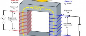
Measurement of current and voltage on the buses of distribution devices and in electronic circuits is done using current transformers or voltage transformers, which serve to reduce the current or voltage of the primary circuits of alternating current electrical installations, as well as to power the coils of measuring devices, relay protection and automation devices connected to their secondary windings
The use of instrument transformers allows:
determine any voltages and currents using ordinary measuring devices with standard windings designed for a voltage of 100 V and a current of 5 A;
separate measuring instruments and relays from voltages above 380 V, ensuring the safety of their maintenance.
The primary winding of the measuring transformer is under the influence of the measured value, and the secondary winding is closed to measuring instruments and protection devices.
Open switchgear
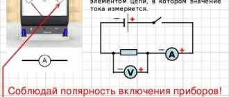
Touching measuring devices specifically included in the high-voltage circuit is unsafe for humans, therefore, in this case, measuring instruments and automatic protection equipment (relays) are connected to the secondary circuit of instrument transformers, connected to the high-voltage circuit only through the magnetic flux in the core. In addition, instrument transformers serve to expand the measurement limits of AC devices, like additional resistors and shunts. The use of instrument transformers with different transformation ratios allows the use of devices with standard measurement limits (100 V and 5 A) when determining a wide variety of voltages and currents.
There are two types of instrument transformers: voltage transformers and current transformers.
Voltage transformers supply voltage windings of measuring devices and relays (voltmeters, frequency meters, meters, wattmeters, voltage relays, power relays, etc.) in installations with voltages of 380 V and higher.
Current transformers supply current windings of measuring devices and relays (ammeters, meters, wattmeters, current, power relays, etc.).
The sources of power supply for most industrial companies are power systems, but some enterprises receive energy from their own industrial power plants. The generation and distribution of energy within the boundaries of the enterprise from its own power stations is carried out mainly in generator mode with a voltage of 6 and 10 kV.
Constant current switchgears of the KV series for voltage 3.3 kV
Electronic circuits of switchgears and substations can be primary and secondary.
Primary circuits include busbar devices and current-carrying parts of devices connected in a certain sequence.
Secondary circuits include circuits with the help of which electronic measurements, relay protection, alarms, remote control and automation are carried out in the primary circuits of switchgear substations, i.e. Secondary circuits provide control, protection, comfortable and non-hazardous service to primary circuits.
Schematic diagrams of primary circuits show all the main elements of an electrical installation: busbar devices, disconnectors, switches, fuses, transformers, reactors, etc., as well as connections between them. In addition to better understanding the operation of the installation and its individual sections, primary circuits usually show main devices and devices of secondary circuits, measuring instruments, relay protection and automation devices without electronic connections.
Modern switchgears may have different connection schemes.
In addition, you need to remember that disconnecting a load-free strip is associated with a break in its charging current, which is greater the longer the line is.
A load switch installed instead of a disconnector allows you to turn off and turn on the line when the load is within the rated limits.
In this case, measuring current transformers are installed at the connection, and line and bus disconnectors are used to relieve voltage from the switch and current transformers during inspection, repair, testing and other work.
Because actions with disconnectors are only possible when the switch is turned off, which breaks the current circuit, the order of disconnecting the strip is as follows: first the switch is turned off, then the line disconnector and finally the bus disconnector. The order of turning on the strip is reversed. This option of connecting to the switchgear is used for lines with heavy loads and huge short-circuit current.
FGC UES completed the installation of 10 kV indoor switchgear equipment at the 110 kV Rosa Khutor substation in the Sochi region
Typically, this scheme is used to connect overhead lines.
In this case, the grounding legs serve to ground and short-circuit the strip after disconnection, because in the disconnected strip there may be the appearance of electronic charges induced by atmospheric electricity or nearby lines. The arresters are designed to discharge electronic charges of atmospheric electricity into the ground, creating significant overvoltages in the switched-on strip that are unsafe for the entire installation. In open switchgears, arresters are connected directly to the main buses.
. To disconnect this transformer from the network, use a bus disconnector (disconnection should only be performed when the transformer is idle); Protection against high and low voltages is provided by fuses.
This circuit includes a switch designed for operational switching and relay protection (RP), the devices of which are powered by measuring current transformers.
The use of complete switchgears and transformer substations makes it possible to reduce installation time, reduce their price and improve quality.
How is electricity distributed and transferred from the main power source to the consumer? This issue is quite complex, since the source is a substation, which may be located at a considerable distance from the city, but at the same time the energy must be delivered with maximum efficiency. This issue is worth considering in more detail.
General description of the process
As mentioned earlier, the initial object from which the distribution of electricity begins is today a power station.
Nowadays, there are three main types of stations that can supply consumers with electricity. This can be a thermal power plant (TPP), a hydroelectric power station (HPP) and a nuclear power station (NPP). In addition to these main types, there are also solar or wind power plants, however these are used for more localized purposes.
These three types of station are both the source and the first point of distribution of electricity.
In order to carry out a process such as the transfer of electrical energy, it is necessary to significantly increase the voltage. The further away the consumer is, the higher the voltage should be. So, the increase can reach up to 1150 kV.
An increase in voltage is necessary in order for the current to decrease. In this case, the resistance in the wires also drops. This effect allows current to be transmitted with minimal power loss.
In order to increase the voltage to the required value, each station has a step-up transformer. After passing through the section with the transformer, the electric current is transmitted to the central distribution center using power lines. The central distribution station is a central distribution station where direct distribution of electricity is carried out.
Facilities such as central distribution centers are already located in close proximity to cities, villages, etc.
d. Not only distribution occurs here, but also voltage reduction to 220 or 110 kV. After this, the electricity is transferred to substations located within the city. When passing through such small substations, the voltage drops again, but to 6-10 kV.
After this, the transmission and distribution of electricity is carried out at transformer points located in different parts of the city. It is also worth noting here that the transmission of energy within the city to transformer substations is no longer carried out using power lines, but using laid underground cables. This is much more expedient than using power lines. The transformer point is the last facility where the distribution and transmission of electricity takes place, as well as its reduction for the last time. In such areas, the voltage is reduced to the already familiar 0.4 kV, that is, 380 V.
Then it is transmitted to private, multi-storey buildings, garage cooperatives, etc. If we briefly consider the transmission path, it is approximately as follows: energy source (10 kV power plant) - step-up transformer up to 110-1150 kV - power transmission line - substation with transformer step-down type - transformer point with voltage reduction to 10-0.4 kV - consumers (private sector, residential buildings, etc.).
Methods of transmitting electricity
There are two ways to transfer electricity:
- Direct transmission method.
- Converting electricity into another form of energy.
In the first case, electricity is transmitted through conductors, which are a wire or a conductive medium. This transmission method is used in overhead and cable power lines. Converting electricity into another form of energy opens up the prospect of wireless supply to consumers. This will eliminate the need for power lines and, accordingly, the costs associated with their installation and maintenance. Below are promising wireless technologies that are being improved.
Technologies for wireless transmission of electricity
Unfortunately, at the moment, the possibilities of transporting electricity wirelessly are very limited, so it is too early to talk about an effective alternative to the direct transmission method. Research work in this direction allows us to hope that a solution will be found in the near future.
Scheme of electricity transmission from power plant to consumer
The figure below shows typical circuits, of which the first two are open-loop, the rest are closed-loop. The difference between them is that open-loop configurations are not redundant, that is, they do not have backup lines that can be used when the electrical load increases critically.
Example of the most common power line configurations
Designations:
- Radial diagram, at one end of the line there is a power plant producing energy, at the other there is a consumer or distribution device.
- The main version of the radial circuit, the difference from the previous version is the presence of branches between the initial and final transmission points.
- Main circuit with power supply at both ends of the power line.
- Ring type configuration.
- Trunk with a backup line (double trunk).
- Complex configuration option. Similar schemes are used when connecting critical consumers.
Now let's look in more detail at the radial circuit for transmitting generated electricity via AC and DC power lines.
Rice. 6. Schemes for transmitting electricity to consumers when using power lines with alternating (A) and direct (V) current
Designations:
- A generator where electricity with a sinusoidal characteristic is generated.
- Substation with step-up three-phase transformer.
- A substation with a transformer that reduces the voltage of three-phase alternating current.
- An outlet for transmitting electrical energy to a distribution device.
- A rectifier, that is, a device that converts three-phase alternating current into direct current.
- The inverter unit, its task is to form a sinusoidal voltage from a constant voltage.
As can be seen from diagram (A), electricity is supplied from an energy source to a step-up transformer, then, using overhead power lines, electricity is transported over considerable distances. At the end point, the line is connected to a step-down transformer and from it goes to the distributor.
The method of transmitting electricity in the form of direct current (B in Fig. 6) differs from the previous scheme by the presence of two converter blocks (5 and 6).
Closing the topic of this section, for clarity, we present a simplified version of the city network diagram.
A clear example of a power supply block diagram
Designations:
- A power plant where electricity is produced.
- A substation that increases voltage to ensure high efficiency in transmitting electricity over long distances.
- High voltage power lines (35.0-750.0 kV).
- Substation with step-down functions (output 6.0-10.0 kV).
- Electricity distribution point.
- Power cable lines.
- The central substation at an industrial facility serves to reduce the voltage to 0.40 kV.
- Radial or trunk cable lines.
- Introductory panel in the workshop room.
- District distribution substation.
- Cable radial or trunk line.
- Substation that reduces voltage to 0.40 kV.
- Input panel of a residential building for connecting the internal electrical network.
Transmission of electricity over long distances
The main problem associated with this task is the increase in losses with increasing length of power lines. As mentioned above, to reduce energy costs for transmitting electricity, the current is reduced by increasing the voltage. Unfortunately, this solution gives rise to new problems, one of which is corona discharges.
From the point of view of economic feasibility, losses in overhead lines should not exceed 10%. Below is a table showing the maximum length of lines that meet the profitability conditions.
Table 1. Maximum length of power lines taking into account profitability (no more than 10% losses)
| Overhead voltage (kV) | Length (km) |
| 0,40 | 1,0 |
| 10,0 | 25,0 |
| 35,0 | 100,0 |
| 110,0 | 300,0 |
| 220,0 | 700,0 |
| 500,0 | 2300,0 |
| 1150,0* | 4500,0* |
* - at the moment, the ultra-high-voltage overhead line has been switched to operating at half the rated voltage (500.0 kV).
Process Features
The production and distribution of electricity, as well as the process of its transmission, has an important feature - all these processes are continuous. In other words, the production of electrical energy coincides in time with the process of its consumption, which is why power stations, networks and receivers are interconnected by such a concept as common mode. This property necessitates the organization of energy systems in order to more efficiently produce and distribute electricity.
It is very important here to understand what such an energy system is. This is a collection of all stations, power lines, substations and other heating networks that are interconnected by such a property as common mode, as well as a single process of producing electrical energy. In addition, the transformation and distribution processes in these areas are carried out under the overall control of this entire system.
The main operating unit in such systems is the electrical installation. This equipment is designed for the production, conversion, transmission and distribution of electricity.
This energy is obtained by electrical receivers. As for the installations themselves, depending on the operating voltage, they are divided into two classes. The first category works with voltages up to 1000 V, and the second, on the contrary, with voltages from 1000 V and above.
In addition, there are also special devices for receiving, transmitting and distributing electricity - switchgear (RU). This is an electrical installation that consists of such structural elements as busbars and connecting busbars, switching and protection devices, automation, telemechanics, measuring instruments and auxiliary devices.
These units are also divided into two categories. The first is open devices, which can be used outdoors, and closed ones, used only when located inside a building. As for the operation of such devices within the city, in most cases it is the second option that is used.
One of the last frontiers of the power transmission and distribution system is the substation. This is an object that consists of switchgear up to 1000 V and from 1000 V, as well as power transformers and other auxiliary units.
Heat energy conversion
One of the oldest energy sources in terms of development and the most important for maintaining human life, without which it is impossible to imagine the life of modern society. In most cases, heat is converted into electricity, and a simple scheme for such transformation does not require connecting intermediate stages. However, in thermal and nuclear power plants, depending on their operating conditions, a preparation stage with the conversion of thermal into mechanical energy can be used, which requires additional costs. Today, direct thermoelectric generators are increasingly used to convert thermal energy into electricity.
The transformation process itself occurs in a special substance, which is burned, releases heat and subsequently acts as a source of current generation. That is, thermoelectric installations can be considered as zero-cycle sources of electricity, since their operation starts even before the appearance of base thermal energy. The main resource is fuel elements – usually gas mixtures. They are burned, resulting in heating of the heat-distributing metal plate. In the process of heat removal through a special generator module with semiconductor materials, energy conversion occurs. Electric current is generated by a radiator unit connected to a transformer or battery. In the first option, energy is immediately supplied to the consumer in finished form, and in the second, it is accumulated and released as needed.
Consideration of power distribution scheme
In order to consider in more detail the process of production, transmission and distribution of electricity, we can take as an example the structural diagram of the supply of electrical energy to a city.
In this case, the process begins with the generators at the state district power station (state district power plant) generating a voltage of 6, 10 or 20 kV. In the presence of such voltage, transmitting it over a distance of more than 4-6 km is not economical, since there will be large losses. In order to significantly reduce power loss, a power transformer is included in the transmission line, which is designed to increase the voltage to values such as 35, 110, 150, 220, 330, 500, 750 kV.
The value is selected depending on how far away the consumer is. This is followed by a point for reducing electrical energy, which is presented in the form of a step-down substation located within the city. The voltage is reduced to 6-10 kV.
It is worth adding here that such a substation consists of two parts. The first part of the open type is designed for voltage 110-220 kV. The second part is closed and includes a power distribution device (PD), designed for a voltage of 6-10 kV.
In addition to those devices that were listed earlier, the energy supply system also includes such objects as a supply cable line - PKL, a distribution cable line - RKL, a cable line with a voltage of 0.4 kV - KL, an input-type switchgear in a residential building – ASU, the main step-down substation at the plant – GPP, an electricity distribution cabinet or a switchboard device, located in the plant workshop, and designed for 0.4 kV.
Also in the circuit there may be such a section as the power center - the CPU. It is important to note here that this object can be represented in terms of two different devices.
This could be a secondary voltage switchgear at a step-down substation. In addition, it will also include a device that will perform the functions of voltage regulation and subsequent delivery to consumers. The second design option is a transformer for the transmission and distribution of electricity, or a generator voltage distribution device directly at the power station.
It is worth noting that the CPU is always connected to the distribution point of the distribution center. The line that connects these two objects has no distribution of electrical energy along its entire length. Such lines are usually called cable lines.
Today, the energy network can use equipment such as KTP - a complete transformer substation. It consists of several transformers, a distribution or input device, designed to operate with a voltage of 6-10 kV. The kit also includes a 0.4 kV switchgear.
All these devices are connected to each other by conductors, and the kit is supplied either ready-made or ready for assembly. Reception and distribution of electricity can also occur on high structures or on power transmission towers. Such structures are called either pole-mounted or mast-mounted transformer substations (MTS).
Transmission of electrical energy. Power lines
Definition 1
Electrical energy transmission is the transportation of electrical energy from places of its generation to consumers.
Currently, electrical energy transmission schemes are used, which include:
- A step-down transformer.
- Step-up transformer.
- Electric generator.
- Power line.
An electrical network is a combination of a generator in which energy is generated, transmission lines through which current flows, and transformers for various purposes that are part of electrical substations along the path of power lines.
Typically, power supply is three-phase, so a power line consists of three phases, each of which may consist of several wires. By design, power lines are divided into cable and overhead.
Finished works on a similar topic
- Course work Transmission and distribution of electricity 410 rub.
- Abstract Transmission and distribution of electricity 220 rub.
- Test work Transmission and distribution of electricity 250 rub.
Receive completed work or specialist advice on your educational project Find out the cost
Overhead power lines are suspended above the ground on special structures called supports. The main advantage of overhead lines is their low cost compared to cable lines. These lines also have better maintainability - there is no need for excavation work to replace the wire; there are no difficulties with visual inspection. The disadvantages of overhead lines include a wide exclusion zone, a low degree of protection from external influences and aesthetic unattractiveness. Overhead AC power lines are divided into several voltage classes.
Cable power lines are laid underground. The cables used may have different designs. The core of the cable is the current-carrying core. Transmission line cables may have both external and intercore insulation. As a rule, oiled paper and transformer oil are used as an insulator, and the outside of the cable is coated with bitumen. The main advantage of cable lines is the absence of exclusion zones, while the disadvantages include the high cost of construction and operation.
— — Do you need help creating a study plan? — Specify a topic and receive a response in 15 minutes — — — — — — get help — —
Most energy is transmitted through alternating current lines. This is due to their main advantage - a step-down line transformer can transmit energy anywhere. And the disadvantage of these lines is inductive reactance, which is associated with electromagnetic induction. Inductive reactance helps reduce the voltage on the way to the consumer from the source. To reduce it, batteries of capacitors can be connected to the line and one wire can be split into several.
DC transmission lines have several advantages over AC lines. The main one is the absence of inductive reactance. The rest include lower metal consumption and lower losses due to corona discharge.
First category of electrical receivers
Today there are three categories of electrical receivers, which differ in the degree of reliability.
The first category of electrical receivers includes those objects where, if the power supply is disrupted, quite serious problems arise. The latter include the following: a threat to human life, severe damage to the national economy, damage to expensive equipment from the main group, massive defective products, destruction of the established technological process for obtaining and distributing electricity, possible disruption of the operation of important elements of public utilities.
Such electrical receivers include buildings with large crowds of people, for example, a theater, supermarket, department store, etc. Electrified transport (metro, trolleybus, tram) also belongs to this group.
As for the supply of electricity to these structures, they must be provided with electricity from two sources that are independent of each other.
Disconnection of such buildings from the network is allowed only for the period during which the backup power source will be started. In other words, the power distribution system must provide for a quick transition from one source to another in the event of an emergency. In this case, an independent power source is considered to be one on which the voltage will remain even if it disappears on other sources powering the same electrical receiver.
The first category also includes devices that must be powered from three independent sources at once.
This is a special group whose operation must be ensured in uninterrupted mode. That is, disconnection from the power supply is not allowed even while the emergency source is turned on. Most often, this group includes receivers whose failure entails a threat to human life (explosion, fire, etc.).
Second and third categories of receivers
Electricity distribution systems with the connection of the second category of electrical receivers include such equipment, if the power is turned off, there will be a massive downtime of working mechanisms and industrial vehicles, a shortage of products, as well as disruption of the activities of a large number of people living both within the city and outside it. outside. This group of electrical consumers includes residential buildings above the 4th floor, schools and hospitals, power plants, the power outage of which will not result in the failure of expensive equipment, as well as other groups of electrical consumers with a total load of 400 to 10,000 kV.
Energy sources of this category should be two independent stations. In addition, disconnection from the main power source of these objects is allowed until the personnel on duty puts the backup source into operation, or the duty team of workers at the nearest power supply station does this.
As for the third category of receivers, these include all the remaining devices that can be powered by just 1 power source. In addition, such receivers may be disconnected from the network during repairs or replacement of damaged equipment for a period of no more than 24 hours.
Schematic diagram of the supply and distribution of electrical energy
Control of the distribution of electricity and its transmission from source to receiver of the third category within the city is most easily accomplished using a radial dead-end circuit.
However, such a circuit has one significant drawback, which is that if any one element of the system fails, all receivers connected to such a circuit will be left without power. This will continue until the damaged section of the chain is replaced. Due to this drawback, it is not recommended to use such a connection scheme.
If we talk about the connection and energy distribution diagram for receivers of the second and third categories, then here you can use a ring circuit diagram.
With this connection, if there is a failure in the operation of one of the power lines, you can restore the power supply to all receivers connected to such a network manually by turning off the power from the main source and starting the backup one. The ring circuit differs from the radial circuit in that it has special sections in which disconnectors or switches are located in the off mode. If the main power source is damaged, they can be turned on to restore supply, but from the backup line.
This will also serve as a good advantage if any repair work needs to be carried out on the main line. A break in the power supply to such a line is allowed for a period of about two hours. This time is enough to turn off the damaged main power source and connect the backup one to the network so that it distributes electricity.
There is an even more reliable way to connect and distribute energy - this is a circuit with parallel connection of two supply lines or the introduction of automatic connection of a backup source.
With such a scheme, the damaged line will be disconnected from the general distribution system using two switches located at each end of the line. In this case, the supply of electricity will be carried out in a still uninterrupted mode, but through the second line. This scheme is relevant for receivers of the second category.
Distribution schemes for the first category of receivers
As for the distribution of energy to power receivers of the first category, in this case it is necessary to connect from two independent power centers simultaneously. In addition, in such schemes, not one distribution point is often used, but two, and a system for automatically turning on backup power is always provided.
For electrical receivers that belong to the first category, automatic switching to backup power is installed on input distribution devices. With this connection system, the distribution of electric current is carried out using two power lines, each of which is characterized by a voltage of up to 1 kV, and is also connected to independent transformers.
Selecting a power distribution scheme
General provisions . The power supply system can be made in several options, from which the optimal one is selected. When choosing it, the degree of reliability, ensuring the quality of electricity, convenience and safety of operation, and the possibility of using advanced methods of electrical installation work are taken into account.
Basic principles for constructing facility diagrams:
— maximum proximity of high voltage sources of 35–220 kV to electrical installations of consumers with PGV, located next to energy-intensive production buildings;
— power backup for certain categories of consumers must be included in the circuit and elements of the power supply system. To do this, lines, transformers and switching devices must carry a constant load in normal mode, and in post-emergency mode, after disconnecting the damaged sections, take over the power supply to the consumers remaining in operation, taking into account the overloads permissible for these elements;
— sectioning the buses of all links of the energy distribution system, and if consumers of the first and second categories predominate, installing automatic transfer transfer devices (ATS) on them.
The schemes are built according to the level principle. Usually two or three levels are used.
The first level of electricity distribution is the network between the facility’s power source and the PGV, if the distribution is carried out at a voltage of 110–220 kV, or between the PGV and the distribution point of 6–10 kV, if the distribution occurs at a voltage of 6–10 kV.
The second level of electricity distribution is the network between the distribution center (or secondary voltage switchgear of the PGV) and the transformer substations (or individual high-voltage electrical receivers).
At small and some medium-sized facilities, only one level of energy distribution is often used - between the power supply center from the system and energy receiving points (TPs or high-voltage electrical receivers).
17 Schemes of electrical networks of industrial enterprises for voltages 6–10
Electrical networks are carried out according to main, radial or mixed schemes.
Radial power distribution schemes are used in cases where receiving points are located in different directions from the power center. They can be two- or single-stage. At small facilities and to power large concentrated consumers, single-stage circuits are used. Two-stage radial schemes with intermediate RP are carried out for large and medium-sized objects with departments located over a large territory. If there are consumers of the first and second categories, the RP and TP are powered by at least two separately operating lines. It is allowed to supply electrical receivers of the second category via one line consisting of at least two cables.
With two-transformer substations, each transformer is powered by a separate line according to the line-transformer block diagram.
In single-transformer substations, mutual power backup of small groups of first category receivers is carried out using cable or bus jumpers on the secondary voltage between adjacent substations.
All switching equipment is installed on the RP or GPP, and on the TP powered from them, predominantly blind connection of transformers is provided. A radial circuit with an intermediate RP, in which the above conditions are met, is shown in Fig. 4.
The radial power supply circuit has great flexibility and ease of operation, since damage or repair of one line affects the operation of only one consumer.
Rice. 4. Radial power supply circuit
Trunk circuits
voltage 6–10 kV are used for linear (ordered) placement of the substation on the territory of the facility, when lines from the power center to the receiving points can be laid without significant reverse directions.
Trunk circuits have the following advantages: better cable loading in normal mode; fewer cameras on the RP.
The disadvantages of trunk circuits include the complication of switching circuits when connecting a transformer substations and the simultaneous disconnection of several consumers powered by the trunk if it is damaged.
The number of transformers connected to one main line usually does not exceed three for transformer power of 1000–2500 kVA and five for power of 250–630 kVA.
Trunk circuits are made single and double, with one-way and two-way power supply.
Single lines without redundancy (Fig. 5, a) are used in cases where the disconnection of one consumer makes it necessary, according to the production technology, to disconnect all other consumers (for example, continuous technological lines).
In Fig. Figure 6 shows a diagram in which closely spaced transformer substations are powered from different single mains with redundancy along connections at low voltage. Such main circuits can also be used for consumers of the first category, if their power does not exceed 20% of the total load of transformers. Transformers are connected to different mains connected to different sections of the switchgear or switchgear.
Rice. 5. Trunk circuits with one-way power supply: a – single; b – double with redundancy at low voltage
Schemes with double (end-to-end) highways (see Fig. 5, b) are used to power critical and technologically weakly interconnected consumers of one facility. Installation of disconnectors at the entrance and exit of the main line is not required.
At large enterprises, two or three main current conductors are used (Fig. 7), laid along different routes through the areas where the main electrical loads are located. At smaller enterprises, circuits with single double-circuit current conductors are used. Reactors are installed on the branches from the current conductors to the distribution point to limit the short-circuit power to the value of the power switched off by VMP type switches. Each transformer feeds two current conductors crosswise, i.e. different circuits of each current conductor are powered by different transformers.
Rice. 7. Trunk circuit for electric power distribution using powerful current conductors
Single and double mains (Fig. with two-way power supply (counter mains) are used when powered from two independent sources required by the conditions for ensuring reliability of power supply for consumers of the first and second categories. When using both sources in normal mode, the main is divided approximately in the middle on one of intermediate substations Sectional switches are normally open and equipped with an ATS device.
Rice. 8. Highways with two-way power supply
Mixed power supply schemes, combining the principles of radial and main power distribution systems, are most widespread at large facilities. For example, at the first level radial schemes are usually used. Further distribution of energy from the distribution point to the workshop transformer substations and high-voltage motors at such facilities is carried out using both radial and mainline schemes.
18 Basic equations and mathematical models of power lines
The power transmission line is the most massive element of the electrical system, connecting the individual nodes of its circuit. Unlike other elements (synchronous electrical machines, transformer equipment, electrical receivers, etc.), it is characterized by one significant feature, namely, it is an element with parameters distributed along its length.
Wave properties of a line.
The transmission of electricity along the lines of the electrical network is due to the propagation of the electromagnetic field in the wires (cable cores) and the space surrounding them. In an overhead line, under the influence of alternating voltage, an alternating magnetic field arises around the wires, as well as an alternating electric field between the phase wires and between each of the wires and the ground. The occurrence of an alternating electric field leads to the appearance of displacement currents (charging currents), the values of which depend on the properties of the dielectric surrounding the conductor and on the potential difference between the wire and the ground, and for a three-phase line, also between the phase wires. Charging currents, superimposed on the load current, determine the gradual change in the total current along the line. The magnetic field strength caused by this current also changes along the line. This, in turn, leads to the fact that the induced EMF of self- and mutual induction turns out to be unequal for different elements of the line length.
long line equations
:
Rice. 1. Schematic representation of a power line
Mathematical models of lines.
The mathematical models mentioned above include line representations:
- symmetrical passive quadripole;
— equivalent circuit (U- or T-shaped);
— own and mutual conductivities.
Rice. 2. Power transmission line (a) and its representation by a four-terminal network (b), a U-shaped equivalent circuit (c) and its own and mutual conductivities (d)