Sources of direct electric current
There are several main types of DC energy sources. Each of them is based on the use of different physical principles and is used in specific conditions. These include the following types:
- mechanical, converting the mechanical energy of rotor rotation into electrical energy;
- thermal, in which thermal energy is converted into electrical energy;
- chemical, in which the energy released as a result of a chemical process is converted into electrical energy;
- light, converting the energy of sunlight into electrical energy.
Electricity is mainly generated by power plants, from which consumers receive not direct current, but alternating current, which is then converted to direct current. But in many areas, only thermal, light or chemical sources of direct electric current can be used.
Designations [edit | edit code]
There are various options for designating a current source. The most common designations are (a) and (b). Option (c) is established by GOST [1] and IEC [2]. The arrow in the circle indicates the positive direction of the current in the circuit at the source output. Options (d) and (e) are found in foreign literature. When choosing a designation, you need to be careful and use explanations to avoid confusion with voltage sources.
Electrical engineering connects the nature of electricity with the structure of matter and explains it by the movement of free charged particles under the influence of an energy field.
In order for electric current to flow through a circuit and do work, it is necessary to have an energy source that converts into electricity:
Read also: Husqvarna saw guide
mechanical energy of rotation of generator rotors;
the occurrence of chemical processes or reactions inside galvanic devices and batteries;
heat in thermostats;
magnetic fields in magnetohydrodynamic generators;
light energy in photocells.
They all have different characteristics. To classify and describe their parameters, a conditional theoretical division into sources has been adopted:
Electric current in a metal conductor
The definition of current and electromotive force in the 18th century was given by famous physicists of that time.
It is considered an ideal source, which is a two-terminal network, at the terminals of which the electromotive force (and voltage) is always maintained at a constant value. It is not affected by the network load, and the internal resistance at the source is zero.
On diagrams it is usually indicated by a circle with the letter “E” and an arrow inside, showing the positive direction of the EMF (in the direction of increasing the internal potential of the source).
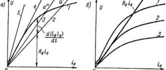
Designation schemes and current-voltage characteristics of EMF sources
Theoretically, the voltage at the terminals of an ideal source does not depend on the load current and is a constant value. However, this is a conditional abstraction that cannot be implemented in practice. In a real source, as the load current increases, the voltage at the terminals always decreases.
The graph shows that the emf E consists of the sum of the voltage drops across the internal resistance of the source and the load.
In reality, voltage sources include various chemical and galvanic cells, batteries, and electrical networks. They are divided into sources:
constant and alternating voltage;
controlled by voltage or current.
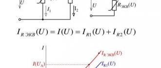
They are called two-terminal circuits that create a current that is strictly constant and does not depend in any way on the resistance value of the connected load, and its internal resistance approaches infinity. This is also a theoretical assumption that cannot be achieved in practice.
Designation schemes and current-voltage characteristics of the current source
For an ideal current source, its terminal voltage and power depend only on the resistance of the connected external circuit. Moreover, with increasing resistance they increase.
A real current source differs from an ideal one in the internal resistance value.
Examples of a current source include:
Secondary windings of current transformers connected to the primary load circuit with their own power winding. All secondary circuits operate in reliable bypass mode. They cannot be opened - otherwise overvoltages will occur in the circuit.
Inductors through which current flows for some time after power is removed from the circuit. Rapid disconnection of an inductive load (sharp increase in resistance) can lead to breakdown of the gap.
A current generator assembled on bipolar transistors, controlled by voltage or current.
In different literature, current and voltage sources may be designated differently.
Types of symbols for current and voltage sources on diagrams
Heat sources
These sources use the thermoelectric effect. Electric current in a closed circuit arises due to the temperature difference between metals or semiconductor structures in contact with each other. At the point of contact, when heated, an electromotive force (thermo-EMF) arises. The electric current of charged particles is directed from the heated area towards the cold one. Its value is proportional to the temperature difference. A thermocouple is formed at the junction.
Devices that use heat released during the decay of radioactive isotope materials to create direct current are radioisotope thermoelectric generators.
Please help, I really need it 1) the movement of which particles creates an electric current in gases?
Please help, I really need it 1) the movement of which particles creates an electric current in gases?
A) electrons b) molecules c) electrons, positive and negative ions 2) the movement of which particles creates an electric current in liquids?
A) electrons b) positive and negative ions c) electrons, positive and negative ions 3) the movement of which particles creates an electric current in metals?
A) electrons b) positive and negative ions c) electrons, positive and negative ions 4) the movement of which particles creates an electric current in vacuum?
A) electrons b) molecules c) positive and negative ions 5) Indicate a device in which current can be created only in one direction a) resistor b) capacitor c) semiconductor diode.
Light sources
The property of semiconductors to create an emf when a light stream hits them is used in the creation of direct current light sources.
Combining a large number of silicon structures makes it possible to create solar cells. Small power plants created on the basis of such solar panels currently have an efficiency of no more than 15%.
Read also
AC Circuit Analysis
Analysis of AC Circuits An example for an AC circuit shows some properties of the steady-state circuit under harmonic influence. In Fig. 0.4 shows a circuit with a power supply of 100 V at a frequency of 100 Hz. We can assume that the input file contains
DC Circuit Analysis
1. Analysis of DC circuits DC circuits are important not only in themselves, but also because many of the techniques used in their analysis are also used in the analysis of AC circuits. In fact, analysis of most electronic circuits and devices can
Analysis for current source circuits using Spice
Analysis for circuits containing current sources using Spice Solutions for circuits containing current sources can be obtained more easily by the node potential method than by the loop current method. Spice modeling is based on the nodal potential method. Remember that everyone
AC circuit analysis (for steady-state sinusoidal modes)
2. Analysis of AC circuits (for steady-state sinusoidal modes) Spice shows the voltages of DC nodes without any special commands, since determining DC voltages is necessary to obtain operating points in
Frequency analysis in series-parallel AC circuits
Frequency analysis in series-parallel alternating current circuits In Fig. Figure 2.13 shows another AC circuit. Parameter values: V=100?0° V; R1=10 Ohm; R2=10 Ohm, L=100 mH and C=10 µF. Let us assume that the resonant frequency is unknown, and it must first be
Connecting a DC voltage source to an RC circuit
Connecting a DC voltage source to an RC circuit In the capacitor shown in Fig. 6.6, when the key is closed, an initial current surge occurs. The input file for this case is:Switch Closing in RC CircuitV 0 PWL(0.0 1us,1V 10ms,1V)R 1 2 10kС 2 0 0.1uF.TRAN 1ms 10ms.PROBE.END Fig. 6.6. Closing the key in
Bias Circuit Analysis
Analysis of bias circuits A circuit with a more stable rest point than in the previous case is shown in Fig. 10.7. It is called an emitter-biased or auto-biased circuit. Input file:Biasing Case StudyVCC 2 0 12VR1 2 1 40kR2 1 0 3.3kRC 2 3 4.7kRE 4 0 220Q1 3 1 4 Q2N2222.LIB EVAL.LIB; the command calls the library
Z-parameters for AC circuits
Z-parameters for AC circuits Z-parameters for an AC circuit like the one shown in Fig. 12.14 can be found using PSpice. We will find the idle parameters for this circuit at a frequency of f=500 Hz. It is convenient to use a current source of 1 A with zero
Timing diagrams for AC circuits with many harmonic sources
Timing Diagrams for AC Circuits with Multiple Harmonic Signal Sources Let us now solve the previous problem by using VSIN components instead of VAC for voltage sources V1, V2 and V3. In this case, a study of the transient process in the time domain is carried out.
Lesson 2 Modeling a DC Circuit
Lesson 2 Modeling a DC circuit Having mastered the material in this lesson and followed the suggested suggestions; You will learn to model DC circuits and determine the value of potentials. You'll also learn how to display the program's output file and find it in
2.1. Currents and voltages in DC circuits
2.1. Currents and Voltages in DC Circuits All voltages that PSPICE calculates are the voltages between individual points on the circuit and one reference point, the location of which you determine yourself by placing the circuit symbol “ground” on the drawing. IN
Lesson 3 AC Circuit Analysis
Lesson 3 AC Circuit Analysis After completing this lesson, you will learn how to use PSPICE to analyze linear AC circuits. You will be able to simulate the operation of electrical circuits consisting of resistors, coils and capacitors (RLC circuits) located in
Lesson 7 DC Circuit Analysis DC Sweep
Lesson 7 DC Sweep Analysis This lesson teaches you how to perform DC Sweep analysis with various variable variables: voltage and DC sources, component temperatures, resistance values. Special attention
7.2. DC source as variable variable
7.2. DC source as a variable variable According to the theory of the construction of electrical circuits, any voltage source with a given source voltage Uq and a given internal resistance R can be replaced with a corresponding current source Iq with
9.4.2. Analysis of Current Transfer in Small Signal Mode
9.4.2. Small-Signal Current Transfer Analysis In small-signal DC transfer analysis, PSPICE determines the small-signal gain, AC input and output impedance of a circuit as part of a DC analysis. At the same time, as always with
9.4.3. Sensitivity Analysis of DC Link Output Voltage to Component Variations
9.4.3. Analyzing the sensitivity of the output voltage of a DC circuit to variations in component parameters. Sensitivity analysis allows you to determine what effect changes in individual circuit parameters have on the output voltage. So you can
Source
Chemical sources
The production of positive and negatively charged particles in chemical direct current sources is carried out through chemical reactions. According to the classification of chemical sources, they are divided into 3 groups:
- galvanic cells, which are primary sources;
- electric rechargeable batteries (AB), or secondary HIT;
*HIT - chemical current sources.
Galvanic cells use a principle of operation based on the interaction of two metals through an electrolyte medium. The type and characteristics of the CIT depend on the selected pair of metals and the composition of the electrolyte. Two metal electrodes of the current source, by analogy with a device of one-way conductivity, are called anode (“+”) and cathode (“-“).
The materials for making the anode can be lead, zinc, cadmium and others. The cathode is made of lead oxide, graphite, manganese oxide, and nickel hydroxide. Based on the composition of the electrolyte, galvanic cells are divided into 3 types:
- salt or “dry”;
- alkaline;
- lithium
In the first two types of elements, a graphite-manganese rod (cathode) is placed along the axis of a zinc cylindrical cup (anode). The free space between them is filled with a paste based on ammonium chloride (saline) or potassium hydroxide (alkaline).
In lithium cells, the zinc anode is replaced with alkaline lithium, which has led to a significant increase in operating time. The cathode material in them determines the output voltage of the battery (1.5-3.7) V. Primary CITs are single-acting sources. Its reagents, which are consumed during operation, cannot be restored.
Batteries are devices in which the electrical energy of an external current source is converted into chemical energy during charging and its accumulation. During operation (discharge), a reverse transformation occurs - chemical energy serves as a source of direct electric current.
The main types of batteries include:
- lead-acid;
- nickel-cadmium alkaline;
- lithium-ion.
To create chemical processes, a set of plates is placed in an electrolyte solution. In batteries created using modern technologies, the solution is not a liquid, but a gel composition (GEL) or honeycomb separators impregnated with electrolyte and placed between lead plates (AGM).
Lead-acid and nickel-cadmium alkaline batteries for operation as DC sources for starting automobile engines are assembled from a set of individual battery cells (“cans”). Each “can” provides a voltage of 2.1 V at its terminals. 6 elements connected in series and placed in a shock-resistant housing have the 12 V necessary for starting the engine at the battery output terminals.
In lithium-ion batteries, lithium ions serve as electric current carriers. They are formed on a cathode made of lithium salt. The anode can be made of graphite or cobalt oxides. The DC voltage at the battery output can vary between (3.0-4.2) V depending on the materials used. These batteries have a low self-discharge current and allow a large number of charge/discharge cycles. Thanks to this, all modern gadgets use batteries of this type.
Physical processes in an electrical circuit
An electrical circuit is a set of technical devices that form paths for closing electrical currents and are intended for the production, transmission, distribution and consumption of electrical energy. Any electrical circuit requires the presence of at least three elements in its structure, namely: energy sources, energy receivers and wires or power lines connecting them. As is known, the carrier of energy is an electromagnetic field, which is concentrated both inside and outside the wires. Thus, to consider the physical phenomena in an electrical circuit in its entirety, it is necessary to calculate and study the electromagnetic field of a given circuit. When physically solving this problem, they use differential concepts and parameters that characterize the electromagnetic field at the point under consideration, such as ` E
,`
H
,`
d
,`
B
,`
D
,
m
, g,
e
. The mathematical description of electromagnetic fields based on differential concepts turns out to be a difficult task.
An electrical circuit usually consists of separate homogeneous sections. In this case, it is possible to describe processes in individual areas with sufficient accuracy for engineering calculations using integral concepts:
electromotive force (EMF) of the energy source;
The application of integral concepts to the calculations of electrical circuits allows one to obtain relatively simple solutions to problems with an acceptable methodological error.
In every real electrical circuit, the following physical processes can be simultaneously observed:
1) the process of generating electrical energy, which occurs in sources (generators) as a result of converting one of the types of energy (mechanical, chemical, etc.) into electrical;
2) the process of converting electrical energy into other types, which occurs in energy receivers;
3) the process of accumulation (or return) of energy in the volume of the magnetic field:
4) the process of accumulation (or return) of energy in the volume of the electric field:
The listed physical processes in one or another combination are inherent in all elements of an electrical circuit, occur simultaneously and are interconnected by the law of conservation of energy.
When calculating the mode of an electrical circuit, it is represented by some conditional circuit or equivalent circuit, consisting of a combination of ideal circuit elements. Each ideal circuit element represents one of the physical processes on the diagram. There are only 5 such circuit elements.
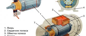
Mechanical DC Power Sources
Devices that convert mechanical energy into electrical energy are turbo and hydro generators. They produce alternating electric current. For the majority of household appliances, the DC source is their power supply. They convert the alternating voltage of the generator into the direct voltage necessary for the operation of the devices. This task is performed by rectifiers, which must provide the necessary power of the DC source for their load and a constant output voltage value, independent of the current consumed.
Power supplies can be linear and switching. Linear blocks are made according to different schemes, the basis of which is:
- half-wave rectifiers;
- full-wave rectifiers.
Rectifiers use the property of semiconductor diodes to pass current in only one direction. The voltage rectified in this way is not yet constant. The capacitances of the smoothing filter capacitors following the rectifier, with their fast charge and slow discharge, maintain the positive unipolar voltage at a certain value. Its value is determined by the transformer receiving voltage from the alternating current generator. For a single-phase home network voltage of 220 V 50 Hz, its steel core has significant dimensions and weight.
Half-wave circuits contain only one semiconductor diode, which passes only one half-wave of a sinusoidal alternating input voltage.
Full-wave rectifiers are made using a bridge circuit or a common-point circuit. In the latter case, the secondary winding of the network transformer has a terminal from its middle. These rectifiers are a parallel connection of two half-wave rectifiers. They act on both half-waves of the alternating input voltage sinusoid.
The bridge rectifier circuit is the most common. The connection of 4 diodes in it resembles a “square”. The alternating voltage of the secondary winding of the network transformer is connected to one of the diagonals. The load is included in another diagonal of the “square”. This will be the input element of the smoothing filter.
Physics. Grade 10
Current source
What happens in the current source?
Separation of molecules of a substance
Converting the energy of ordered motion of charged particles into heat
Converting electrical energy into mechanical energy
Separation into positive and negative electrical charges
Substituting elements into gaps in text
Fill in the blanks in the text.
Heating of a metal conductor occurs as a result of the collision of electrons with. They transfer their energy.
Formulas of physical quantities
Establish a correspondence between physical quantities and units of measurement of these quantities.
Work of electric current
Electric current power
Work of electric current
Fill in the blank in the text by selecting the correct answer from the drop-down menu.
A current flows in a conductor under a voltage of 200 V for 2 minutes at a current strength of 4 A. In this case, work is done by the current.
Joule–Lenz law
Fill in the blank in the text by selecting the correct answer from the drop-down menu.
If the time it takes for the current to pass through the conductor is reduced by 2 times and the resistance of the conductor is reduced by 2 times, then the amount of heat released by the conductor with current is .
Electricity
Select with your mouse 4 words that relate to the topic of the lesson.
1. An elementary particle that has the smallest negative charge.
2. Russian physicist who worked in the field of electromagnetism.
3. What other effect, besides magnetic and chemical, does electric current have?
4. Italian scientist, after whom the elements - chemical sources of current - are named.
Resistance, power and current work
Connect pentagons and ovals in pairs so that each pair is the answer to the questions in the next problem.
The current in an electric lamp is 0.2 A at a voltage of 120 V. Find its resistance, power and current work in three minutes (in SI units).
Electricity
Electricity
Connect geometric shapes in pairs so that each pair is the answer to the questions in the problem.
U is applied to the ends of a long homogeneous conductor
.
The conductor was replaced with another one, made of the same material, the same length, but with a smaller cross-sectional area, and the same voltage U
. What will be the voltage, current power and resistance of the conductor?
Work of electric current
Answer the questions to solve the crossword puzzle.
The lamp resistance is 60 Ohms, the current in it is 3.5 A.
Joule–Lenz law
Answer the questions to solve the crossword puzzle.
The current in an electric lamp is 0.2 A at a voltage of 220 V. Calculate:
Electric current power
Fill in the blank in the text. Give your answer as a whole number.
The plugs on some household electrical appliances are labeled “6 A, 250 V.” The maximum permissible power of electrical appliances that can be turned on using such plugs is W.
Source control
To ensure a constant value of the output voltage level, independent of the current consumed by the load and fluctuations in the input AC voltage, all modern DC power supplies have a stabilization and regulation stage.
In it, the output voltage is compared with a standard (reference) value.
When a difference appears between them, a control signal is generated, which changes the output voltage through the control circuit. The value of the reference voltage can be varied within wide limits, having at the output of the regulated DC power supply the voltage necessary for operation.
Pulse sources
Circuits using input network voltage transformers are called linear. In switching power supplies, double conversion is performed - first, the alternating voltage is converted into direct voltage by the rectifier, then an alternating pulse voltage of a higher frequency is generated, which is again converted into a direct voltage of the required value in the output stage.
Pulse generators produce a continuous pulse sequence with a frequency of (15-60) kHz. The output voltage is regulated by pulse width modulation (PWM), in which the signal level at the output of the power supply is determined by the width of the pulses generated by the generator and their duty cycle value. Regulated pulse-type DC power supplies are increasingly used in the creation of equipment for various purposes.
Comparison of sources
The absence of a powerful input transformer in switching power supplies makes it possible to create designs that are much lighter and have smaller linear dimensions. Their efficiency is significantly higher than sources made according to linear circuits. The efficiency reaches 98%. In them, microcircuits that perform the functions of controllers are widely used.
Each type of stabilized direct current sources finds application in its own field. And it is very diverse. The basis is the characteristics of direct current sources. Linear sources provide low output voltage ripple and low noise levels. This is achieved by the absence of switching during their operation, which creates a high level of interference in a wide frequency range. In pulsed sources it is necessary to use complex circuit solutions to combat them, which leads to an increase in the cost of products in which they are used.
Letter designations
In electrical diagrams, in addition to graphic symbols, alphabetic symbols are also used, since without the latter, reading the drawings will be quite problematic. Alphanumeric marking, just like UGO, is regulated by regulatory documents, for electrical this is GOST 7624 55. Below is a table with BO for the main components of electrical circuits.
Letter designations of main elements
Unfortunately, the size of this article does not allow us to provide all the correct graphic and letter symbols, but we have indicated regulatory documents from which all the missing information can be obtained. It should be taken into account that current standards may change depending on the modernization of the technical base, therefore, we recommend monitoring the release of new additions to regulations.
Source