Why do you need to calculate voltage losses in a cable?
The background is this. The designers were given technical specifications for the power supply project, which indicated the power of the refrigeration systems. While the project was being implemented and money was allocated for its implementation, refrigeration equipment was purchased with a power consumption that was 2 times higher than the original one. In addition, it turned out that the actual distance to the substation will be almost 2 times greater...
In general, expensive German refrigeration equipment refuses to work, everyone knows what to do, but no one wants to pay for it. Last summer, due to low voltage (linear 340-360 V), a compressor worth more than 10 thousand euros burned out. This could no longer be tolerated. I was asked to carry out calculations, monitoring and measurements on the power system, and make recommendations to solve the problem.
Since I wrote this report on behalf of a company that has a license for energy audits, this document will be valid in the upcoming litigation.
As the document progresses, I will provide comments and clarifications in quotes.
Introduction
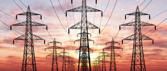
An examination was carried out of the quality of electricity supplied from the transformer substation (TS) along the first section (440 m) to main switchboard 2.2 and further along the second sections (50 and 40 m) to the refrigeration units (System 12 and System 14).
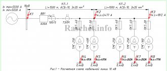
Structural diagram of this system:
Diagram of cable lines from transformer substation to load. There is a diesel power plant - a diesel power plant, but is not considered in this case.
The purpose of the survey is to identify the causes of a significant voltage drop on the cable line.
System 12 includes the following consumers:
| Name | Installed power, kW | Max rated current, A |
| Air cooler | 124,6 | 50,5 |
| Air cooler | 78,3 | 27,1 |
| Compressor motors | 100 | 132,7 |
| Fan motors | 13,7 | 29,7 |
| Total | 316,6 | 240 |
System 14 includes the following consumers:
| Name | Installed power, kW | Max rated current, A |
| Air cooler | 234,4 | 81,2 |
| Air cooler | 193,9 | 55,7 |
| Air cooler | 15,2 | 31,3 |
| Compressor motors | 396 | 525,6 |
| Fan motors | 66 | 144,3 |
| Total | 905,5 | 838,1 |
Supply voltage – 380…415 V.
The values of currents, powers and voltages are taken from the passport data of consumers.
Preliminary calculation of voltage losses in the cable
According to preliminary calculations, when the voltage at the output of the transformer is 415 V at idle (with the load off), at maximum load a drop of 35 V, or 8.43%, is permissible. In this case, at maximum load, the voltage will drop to 380 V, which, according to consumer data sheets, is acceptable.
The transformer substation contains 2 transformers of 600 kW each, which were planned to be used one at a time. But due to the increase in load, they had to be included in parallel.
According to the Code of Rules for the design and construction of SP 31-110-2003, as well as GOST R 50571.15-97, taking into account regulated deviations from the nominal value, the total voltage losses from the busbars of 0.4 kV TP to the most distant load in residential and public buildings should not exceed 9%. Moreover, 5% of them are in the section from the transformer substation to the ASU, and 4% in the section from the ASU to the consumer.
According to GOST 29322-2014, the rated phase voltage in three-phase networks should be 400 V, and under normal operating conditions the supply voltage should not differ from the rated voltage by more than +-10%.
Based on this, a drop of 8.43% is justified and complies with the Rules and GOSTs adopted in the Russian Federation.
Calculation of voltage drop for the 1st section
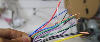
During the examination, the following was revealed. From the transformer substation, located at a distance of 440 m, electricity is supplied to Main Switchboard 2.2 via a cable line consisting of four parallel-connected AVBbShv 4x240 cables, with a total cross-section of 960 mm2.
Internals of main switchboard 2.2. At the top is the input from the TP to the input contactor-protective circuit breaker, to the right are the busbars from the automatic transfer switch (reserve - diesel), below is the output circuit breaker, and the outputs to the Systems.
The maximum calculated load current, according to the passport data, is 240 A for System 12 and 838.1 A for System 14. Therefore, the maximum cable line current is 240 + 838.1 = 1078.1 A.
The total installed power, according to the data sheet, is 316.6 kW for System 12, and 905.5 kW for System 14. Therefore, the total installed power of the entire load is 316.6 + 905.5 = 1222.1 kW.
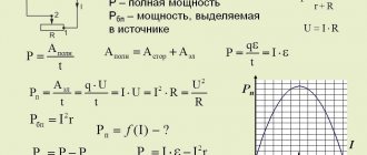
Let's calculate the voltage drop on the cable line of the 1st section from the transformer substation to the main switchboard 2.2 using the formula:
Δ U=√3 I(R cos φ L+X sin φ L)
Initial data for calculation:
- Maximum current I = 1078.1 A,
- Installed load power 1222.1 kW,
- Specific active resistance of one core R = 0.125 Ohm/km according to the cable manufacturer.
- Specific inductive reactance of one core X = 0.077 Ohm/km according to the cable manufacturer.
- We accept Cosφ = 0.8, then sinφ = 0.6
- Cable core material – aluminum,
- Line length L = 0.44 km.
Substituting the data into the formulas, we find that for one cable the drop will be 239 V, or 57.75%. Then for the existing cable line of the 1st section the voltage drop will be 59.8 V, or 14.43%.
Such a voltage drop in only the 1st section is unacceptable.
This is the basic formula. I did the calculations using a calculator. I checked the received data using the Electrician program (subprogram “Losses”).
In addition, Igor Krivulets (220blog.ru) helped me a lot, for which I thank him very much! At the end of the article there will be a video on the topic of voltage drop.
There are also good books on electrical engineering, download them directly from my blog!
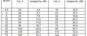
Just in case, a table of active and inductive resistances of aluminum and copper cables of different sections:
Table of active and inductive resistances of aluminum and copper cables of different sections
The result of the survey of the 2nd section (System 12)
After the GRShch2.2 switchboard, the second section of the cable line to System 12, consisting of one AVVG-ng-LS 5×185 cable, 50 m long, goes to the load.
Data for calculation:
- Maximum current 240 A,
- Installed load power 316.6 kW,
- Specific active resistance of one core R = 0.164 Ohm/km according to the cable manufacturer.
- Specific inductive reactance of one core X = 0.077 Ohm/km according to the cable manufacturer.
- Cable core material – aluminum,
- Line length L = 0.05 km.
For an existing cable line, the voltage drop will be 3.67 V, or 0.88%.
The result of the survey of the 2nd section (System 14)
After the GRShch2.2 switchboard, the second section of the cable line to System 14 goes to the load, consisting of three parallel-connected cables AVVG-ng-LS 5×185 with a length of 40 m.
Data for calculation:
- Maximum current 838.1 A,
- Installed load power 905.5 kW,
- Specific active resistance of one core R = 0.164 Ohm/km according to the cable manufacturer.
- Specific inductive reactance of one core X = 0.077 Ohm/km according to the cable manufacturer.
- Cable core material – aluminum,
- Line length L = 0.04 km.
For one cable, the voltage loss will be 10.2 V, or 2.47%. For the existing cable line of the 2nd section of System 14, the voltage drop will be 3.4 V, or 0.82%.
Recommendations for upgrading cable lines
For a given maximum current and line length, a different cable line for Section 1 must be selected because the calculated voltage drop for that section is unacceptable. Based on the preliminary calculation data and the voltage drop data in 2 sections, the voltage drop in the 1st section should be no more than 7.55%.
This level of losses will be provided by a cable line consisting of 8 AVBbShv 4x240 cables connected in parallel. That is, add additional cables (4 pieces) to the existing cables (4 pieces).
As a result, the losses on the cable line of section 1 will be 7.2%, or 29.8 V.
The cable lines of 2 sections do not need modernization.
conclusions
For stable operation of refrigeration equipment, according to its passport data, a voltage with permissible limits of 380 to 415 V is required.
If we take into account the recommendations given, then with an output voltage of the TP of 415 V at maximum load, the voltage loss for System 12 will be 7.2 + 0.88 = 8.08%, or 33.6 V. As a result, at maximum load, the supply voltage of System 12 will be not less than 381.4 V.
For System 14, the losses will be 7.2 + 0.82 = 8.02%, or 33.2 V. As a result, at maximum load, the supply voltage of System 14 will be at least 381.7 V.
Voltage quality measurement results
The measurements were carried out using a HIOKI 3197 , which allows you to take all voltage parameters online.
The device is designed to plot graphs of various power supply parameters in real time. I have already used HIOKI 3197 in voltage quality analysis for problems with refrigerators. If anyone needs such a device, please contact us!
The measurements were carried out at the connection point of the 2nd section of System 14 in different operating modes of the equipment. The 2nd section of System 12 was not examined because it could not be accessed without turning off the power supply to the TP. But since System 12 is low-power compared to System 14, measurements are sufficient to get an overall picture, the results of which are shown in the graphs below.
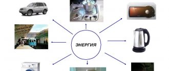
Voltage monitoring result
Current monitoring result
Explanations for the graphs.
Peak current consumption (switching on the load at 100% power) occurs at 16:56. In this case, the phase voltage (averaged over phases) is 212 V (linear - 367 V), the current is 836 A.
The transformer is idle (the load is completely turned off) at 17:07. In this case, the phase voltage is 238 V (linear - 412 V), the current is 0 A.
System 12 was turned off when measurements were taken.
Based on the results of the measurements, it can be concluded that the maximum total voltage drop for System 14 is 45 V, or 11%.
These measurements confirm the correctness of the calculations and recommendations made.
Photo of connecting the HIOKI 3197 device to the cable line during the measurement process:
Connecting HIOKI 3197 for real-time voltage measurements
Backup power
Backup power in the main switchboard 2.2 comes from a diesel power plant (diesel power plant). Switching is done through the ATS (automatic transfer switch) system.
Backup power supply parameters:
- Maximum power of diesel power plant – 600 kW,
- Cable line – 3 cables AVBbShv 4x240, connected in parallel,
- Cable line length – 250 m.
Based on these parameters, we can clearly conclude that the capacity of the diesel power plant and the backup cable line, taking into account the voltage drop, will be enough for no more than half of the maximum load requirements, which is completely unacceptable.
Therefore, it makes no sense to monitor the quality of food through the diesel power station.
For backup power in this case, it is recommended to use a diesel power plant with a power of at least 1220 kW. The cable line must contain 5 AVBbShv 4x240 cables, in which case the voltage drop to the main switchboard 2.2 will be an acceptable value of 6.5%.