PUBLIC JOINT STOCK COMPANY "FEDERAL GRID COMPANY OF UNITED ENERGY SYSTEM"
A STANDARD OF ORGANIZATION STO 56947007-
ShchR]. PJSC FGC UES 29.240L0.249-2017
Rules
design of electrical circuit diagrams of substations
Organization standard
Date of introduction: 09.28.2017 Date of introduction of changes: 31.07.2018
PJSC FGC UES 2017
Preface
The goals and principles of standardization in the Russian Federation are established by the Federal Law of December 27, 2002 No. 184-FZ “On Technical Regulation”, objects of standardization and general provisions in the development and application of standards of organizations of the Russian Federation GOST R 1.4-2004 “Standardization in the Russian Federation. Organization standards. General provisions", rules for the construction, presentation, design and designation of national standards of the Russian Federation, general requirements for their content, as well as rules for design and presentation of changes to national standards of the Russian Federation - GOST R 1.5-2012.
Information about the organization standard
1. DEVELOPED: Substation Department.
2. INTRODUCED: Department of Substations, Department of Innovative
development.
3. APPROVED AND ENTERED INTO EFFECT: By Order of PJSC FGC UES dated September 28, 2017 No. 390.
4. CONNECTED: with SO UES JSC by letter dated 06/21/2017 No. B31-P-2-19-7514.
5. CHANGES INTRODUCED: By Order of PJSC FGC UES dated July 31, 2018 No. 288 to clauses 4.6; 5.1; 5.6; 5.8; Appendices A, B, E and D.
6. CHANGES HAVE BEEN CONSOLIDATED: By letter from SO UES JSC
dated 09/03/2018 No. ВЗ1-1-2-19-9788.
7. INTRODUCED: as amended on July 31, 2018 (REPEATED).
Comments and suggestions on the organization standard should be sent to the Department of Innovative Development of PJSC FGC UES at the address 117630, Moscow, st. Ak. Chelomeya, 5 A, by email at
This document cannot be fully or partially reproduced, replicated or distributed as an official publication without the permission of PJSC FGC UES.
2
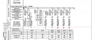
Appendix B
| 10 75_ ,_50_ IN 20 |
| Table D.1. Parameters of the main equipment indicated on the SEP |
| 13 |
| l" ■III | 11P11MS110VPMMS OOOP.Y.lOBiHIIIU | 11 Equipment parameters seam pin | Example |
| 1. The selected primary rated current is highlighted. 2. If the current transformer has only one value of the transformation ratio, then the rated current is not emphasized. | |||
| 6 | Built-in current transformer | Accuracy classes of secondary windings Rated current: primary (options) and secondary (transformation ratio) 1. The selected primary rated current is highlighted. 2. If the current transformer has only one value of the transformation ratio, then the rated current is not emphasized. | Built-in current transformer 0.2S/0.2-(400-300-200/n 10Р/10Р/10Р-(2000-1000-800/1) |
| 7 | Voltage transformer: capacitive, inductive (specify) | Rated voltage (line-to-line) Rated capacity of the voltage divider (for capacitive) Rated voltages of the windings Accuracy classes of the secondary windings | Capacitive voltage transformer 500 kV, 4650 pF, ^/7^/7^ /OD; 0.2/ZR/ZR |
| 8 | Surge Limiter (SPL) | Rated voltage | 750 kV surge arrester |
| 9 | Shunt reactor | Rated power Rated voltage | ROMBSM-60000/500 3×60 Mvar, 525/V3 kV |
| 10 | Controlled shunt reactor | Rated power, Rated voltage | RODU-60000/500 3×60 Mvar, 525/V3 kV |
| 11 | Reactor current-limiting | Rated voltage Rated current, reactance | Current-limiting reactor 10 kV, 1000 A, 0.56 Ohm |
| 12 | coupling capacitor | Rated voltage, rated capacity | Coupling capacitor kV, 6400 pF l/z |
| 13 | High frequency suppressor (HF) | Rated voltage, rated current | HF suppressor 110 kV, 2000 A |
| 14 | Auto switch | Rated current | Circuit breaker 1600 A |
| 15 | Fuse | Rated voltage, rated current of fuse link | Fuse 10 kV, 600 A |
| l" ■III | 11P11MS1101$PMMS ooopvioiiiilllliu | 11 Equipment parameters seam pin | Example |
| 16 | Busbars | Rated current, phase design (not specified for switchgear and switchgear) | Busbars 2000 A, 3 x AC 400/51 |
| 17 | Bare wires, rigid busbars used for busbars of outdoor switchgear cells | Rated current, phase design | 2000 A, 3 x AC 400/51 |
| 18 | Cables used for busbar | “number of groups” x “number of cables in a group” x “cable brand” - “number of cores” x “core cross-section”/“screen cross-section” - “rated voltage” | Zx 1xPvVng(A)-b8- 1×95/16-10 |
| 19 | Arc suppression reactor | Rated voltage Rated power | DGR 35 kV, 0.84 MBA |
| 20 | Grounding arc extinguishing unit | Rated voltage, rated power, current adjustment range, winding connection diagram | Grounding arc extinguishing unit 10, 3.15 Mvar, 500-50 A, Un/D |
| 21 | Compensation reactor | Rated voltage Reactor power | Compensation reactor 35 kV, 31 Mvar |
| 22 | Static capacitor bank (SCB) | Rated voltage Rated power | Static capacitor bank 126 kV; 52 Mvar |
| 23 | Static thyristor compensator (STK) | Rated voltage Rated power | STK 35 kV, 40 Mvar |
| 24 | Static compensator (STATCOM) | Rated voltage Rated power | STATCOM 15.75 kV, 50 Mvar |
| 25 | Synchronous compensator (SC) | Rated voltage Rated power | SK 10.5 kV, 50 Mvar |
| 26 | Asynchronized compensator (ASC) | Rated voltage Rated power | ASK 10.5 kV, 50 Mvar |
| 27 | Linear control transformer | Rated voltage, power, regulation ranges | LRT 10 kV, 16 MBA, ±10×1.5% |
| 28 | Diesel generator installation | Rated active power, rated power factor | DGS 1000 kW, cos (p = 0.8 |
| 29 | Grounding switches | Rated voltage, thermal current For GIS, high-speed ones are additionally specified grounding conductors | Grounding switch 10 kV, 20 kA |
| 30 | Connection filter | Bandwidth | Connection filter 77-1000 Hz |
| l" 1111 | Name oooru/yuwanmi | 11 parameters oooru. seam them | Example |
| 31 | Zero sequence current transformer | Rated voltage | TTNP 0.66 kV |
| 32 | Busbar | Rated voltage, rated current | Busbar 10 kV, 2000 A |
| 33 | Conduit | Rated voltage, rated current | SF6 current conductor 500 kV, 1000 A |