Operational diagram and layout of electrical connections of power plants and substations
The basic requirements for operational circuits and layout circuits are set out in the above paragraph 10.1 “Instructions for switching in electrical installations”.
On the prepared operational diagrams of electrical connections of power plants and substations, all switching devices and stationary grounding devices are depicted in a position (on or off) corresponding to the normal mode diagram approved by the chief engineer of the station or electrical network enterprise.
The equipment of new connections, to which voltage can be supplied by turning on the switching devices, is considered operational and is plotted on the operational diagram.
Operational diagrams and layout diagrams reflect all changes in the positions of switching devices, relay protection and automation devices, the location of portable grounding and the inclusion of grounding knives.
When returning to duty, the personnel hand over to the shift an operational diagram (layout diagram) of the electrical installation indicating on it the actual positions of the switching devices, disconnected relay protection and automation devices, as well as grounding devices.
The actual positions of switching devices, disconnected relay protection and automation devices and grounding devices are indicated by applying symbols on the operational diagram directly to the graphic designation of the device or next to the graphic designation of the corresponding device (device), if the position of the device (device) has been changed.
Signs are applied with pencil, ink or red paste.
Sign "Z!" - relay protection device is disabled - placed next to the graphic designation of the protected equipment (generator, transformer, line, busbars).
Sign "A!" - the automation device is disabled - is applied next to the graphic designation of the switch that is affected by the automatic device.
When removing portable grounding from equipment, as well as when switching on a previously disconnected relay protection or automation device, the corresponding signs on the operational diagram are crossed out with a pencil, pen (ink or paste) of a dark color.
Correction of erroneously applied signs is not permitted. Incorrect signs are circled in blue, and correct signs are placed next to them.
The duration of the operational scheme is not limited; a new operational plan is drawn up as needed.
The operational scheme has a serial number. When handing over the duty, the operational scheme is signed by the person handing over and taking over the duty, indicating the date and time.
When using layout diagrams, maintaining operational diagrams is not necessary.
On the layout diagrams, all changes in the positions of switching devices, relay protection and automation devices, grounding devices are reflected using symbols of switching devices and hanging conventional signs. The procedure for maintaining a layout diagram of an electrical installation is indicated in the instructions of the power company.
It is allowed to maintain an operational diagram on a computer. The procedure for maintaining an operational diagram on a computer is also established in the instructions of the energy company.
Switching forms
A switching form (usual) is an operational document that provides a strict sequence of operations with switching devices, grounding disconnectors (knives), operational current circuits, relay protection devices, emergency and operational automation, operations to check the absence of voltage, applying and removing portable groundings , hanging and removing posters, as well as necessary (according to the conditions of personnel safety and equipment safety) inspection operations.
A standard switching form is an operational document that specifies a strict sequence of operations when performing repeated complex switching in electrical installations of different control levels or different power facilities.
Switching forms establish the order and sequence of operations when carrying out switching in electrical connection diagrams of electrical installations and relay protection and automation circuits.
Using switching forms, complex switchings are performed, as well as all switchings (except single ones) on electrical installations that are not equipped with interlocking devices or have faulty interlocking devices.
Along with conventional switching forms, standard programs and standard switching forms are developed and used for repeated complex switchings.
Complex ones include switching that requires a strict sequence of operations with switching devices, grounding disconnectors and relay protection devices, emergency and regime automation. When performing the sequence of operations specified in the programs and switching forms, the safety of operating and maintenance personnel is ensured and the occurrence or development of disturbances in the operation of the electrical installation is prevented.
When making complex switchings, replacing forms or switching programs with any other operational documents is not allowed.
For each power plant, substation and electrical installation of distribution power grids, lists of switching types performed using conventional switching forms, standard forms and switching programs are developed, as well as a list of switching types that can be performed without switching forms. Each list indicates the number of operational personnel involved in certain switches.
Lists of complex switchings, approved by the technical managers of the relevant power facilities, are stored at control centers, central (main) control panels of power plants and substations.
Lists of complex switchings are revised when the circuit, composition of equipment, and relay protection and automation devices change.
The usual switching form is drawn up by operational or operational-repair personnel who will make switches after recording the order in the operational log.
It is allowed to draw up a switching form by the specified personnel in advance during the shift.
Standard switching forms are developed in advance by the personnel of power enterprises in relation to complex switchings in the main electrical connection circuit of an electrical installation, in auxiliary circuits, and relay protection and automation devices, taking into account the fact that switchings containing operations with secondary switching equipment in emergency system automation circuits are among the complex ones.
Standard switching forms are signed at power plants by the heads of electrical shops and their deputies for relay protection and automation; at electrical network enterprises - heads of dispatch services and heads of local relay protection and automation services.
Standard forms for switching to substations are agreed upon with the heads of the relevant dispatch service, in whose operational management the equipment is located, and approved by the chief engineer of the enterprise.
Switching programs (standard programs) are used by operational managers when making switching in electrical installations of different management levels and different power facilities.
The switching program is approved by the head of the dispatch control, who is operationally subordinate to all switched equipment.
The level of detail of programs is taken to correspond to the level of dispatch control.
Persons directly performing switching operations are permitted to use the switching programs of the corresponding dispatcher, supplemented by switching forms.
Standard programs and switching forms are promptly adjusted in the event of changes in the main electrical connection diagram of electrical installations associated with the introduction of new equipment, replacement or partial dismantling of obsolete equipment, reconstruction of the switchgear, as well as the inclusion of new relay protection and automation devices or changes in electrical installations.
With planned changes in the circuit and operating modes of the power system and changes in relay protection and automation devices, the production services of power systems, which manage the equipment and relay protection and automation devices, make the necessary changes and additions in advance to standard programs and switching forms at the appropriate levels of operational management.
Switching forms (standard forms) are used by operational dispatch personnel who directly perform switching.
Switching forms establish the order and sequence of operations when carrying out switching in electrical connection diagrams of electrical installations and relay protection and automation circuits.
The switching form (regular and standard) records all operations with switching devices and operational current circuits, operations with relay protection and automation devices (as well as with the power circuits of these devices), operations on turning on and off grounding blades, applying and removing portable groundings, phasing operations equipment, results of inspection of support-rod insulators (presence of cracks and chips) before performing operations with disconnectors, operations with telemechanics devices and others in a certain sequence of their implementation.
The switching forms indicate the most important personnel check actions:
checking the absence of voltage before applying grounding (turning on grounding blades) to live parts;
on-site check of the switched-on position of the busbar before commencing operations to transfer connections from one bus system to another;
on-site check of the open position of the switch, if the next operation is with disconnectors;
checking on site or using signaling devices the position of each switching device of the primary circuit after the device has performed an operation;
checking at the end of the switchings the compliance of the switching devices in the relay protection and automation circuits with the regime cards.
Each operation (or action) in the switching form is recorded under a serial number.
Immediately before switching using a regular switching form, the correctness of the operations recorded in it is checked using an operational diagram (or layout diagram), which accurately reflects the actual position of the switching devices of the electrical installation at the time of verification.
After checking, the switching form is signed by two persons - those performing the switching and those monitoring them.
When switching is carried out by one person from the operational staff, the correctness of the switching form is controlled by the operational manager who gave the order for the switch, and his name is entered on the form.
At power plants, when the shift supervisor of the electrical shop (as a supervisor) and the electrician on duty (as the one performing the operations) participate in switching operations, the inscription “I authorize switchings” is written on the switching form, signed by the power plant shift supervisor.
When using standard switching forms, the following conditions are met:
the decision to use a standard switching form when performing specific operations is made by the person performing the switching and the supervisory person;
the standard switching form indicates for which connections, when performing which task and for which electrical installation diagram it can be used;
Before starting switching, the standard switching form is checked against the operational diagram or layout diagram of the electrical installation by the supervisor. On checking the standard switching form and the correctness of the sequence of operations and verification actions set out in it, in the operational log after recording the dispatcher's order for switching, a record is made that the corresponding standard switching form has been checked, corresponds to the diagrams and switching in the sequence specified in it can be performed. It is allowed to make the specified entry in the standard switching form signed by the person performing the operations and the person controlling the switching data;
It is not allowed to use a standard switching form if the electrical installation diagram or the state of the relay protection and automation devices does not correspond to the diagram for which the standard form was drawn up. Operational personnel are not allowed to make changes or additions to the standard switching form if it corresponds to the scheme and specifications;
if changes have occurred in the primary connection diagram or in the electrical installation circuits that exclude the possibility of performing operations on individual items of the standard switching form, or errors are found in it, the operating personnel of the power plant, the substation makes an appropriate entry in the operational log and informs the persons who signed the standard form about this switches, or persons replacing them by position, as well as the operational manager. The use of a standard form in this case is not permitted; a regular switching form is drawn up;
in the case when, when using a standard switching form for carrying out the next operation on a given electrical installation, it is necessary to receive an order from the dispatcher (for example, an order to turn on the grounding knives on a disconnected power line), in the standard switching form, before recording this next operation, an o.
In case of complex switching in electrical installations using conventional and standard switching forms, it is allowed to involve persons from among the employees of local relay protection and automation services assigned to these devices in performing individual operations in relay protection and automation circuits. The relay protection and automation service worker involved in the switching checks the correctness and order of the operations recorded in the switching form, signs the switching form as a participant in the switching and performs the next operations in the relay protection and automation circuits on the orders of the person performing the switching in the primary connection diagram. In this case, orders and messages about their implementation can be transmitted using communication means.
Switching forms (regular and standard) are reporting documents and are strictly accounted for.
Backup copies of operational switching forms (both regular and standard) issued to operational personnel are numbered. The numbers of all backup switching forms issued to operational personnel are recorded in the operational log. When turning in a shift, the numbers of the last used (filled out) forms are indicated. Used switching forms (including damaged ones) are stored in the order of their numbers.
Already used switching forms are stored for at least 10 days.
The correctness of filling out, applying and maintaining reports on switching forms is periodically monitored by the management of the electrical department at power plants and operational personnel in electrical networks.
The following is a recommended form for the switching form.
Chapter 13. Requirements for personnel of energy enterprises
General provisions
When organizing and carrying out any work on operation, maintenance and repair of power equipment, priority is given to labor protection and safety measures.
The rules for working with personnel at power plants, substations and other energy enterprises are regulated by the current PTE and “Inter-industry rules for labor protection (safety rules) during the operation of electrical installations”, as well as the current “Rules for working with personnel in electric power industry organizations of the Russian Federation”, approved by order of the Ministry of Energy of Russia dated 19 February 2000 No. 49.
The requirements of these Rules must be reflected in instructions and regulations, as well as in organizational and administrative documents in force in electric power organizations.
In table 13.1. The basic terms related to the personnel of energy enterprises and their definitions are given.
Table 13.1
Continuation of the table. 13.1
End of table. 13.1
Responsibility for working with personnel lies with the head of the organization or an official from among the management employees of the organization, to whom the head of the organization delegates this function and the corresponding rights.
If the head of the organization transfers his rights and functions for working with personnel to an official from among the management employees, all decisions regarding personnel can be made by this official.
Work with personnel is one of the main directions in the activities of the organization and its structural divisions.
In table 13.2 shows the mandatory forms of work with various categories of workers.
Table 13.2
End of table. 13.2
Work with persons combining professions (positions) is carried out in full according to their main and combined professions (positions).
The head of the organization, in accordance with the law, should not allow employees to perform their job duties who have not undergone training, instruction, internship, knowledge testing on labor protection, mandatory medical examinations, as well as in the case of medical contraindications.
In accordance with the order of the Ministry of Health and Social Development of the Russian Federation dated August 16, 2004 No. 83, personnel engaged in maintenance and repair of existing electrical installations with voltages of 42 V and above AC, 110 V and above DC, as well as installation, commissioning, testing and measurements in these electrical installations, is required to undergo preliminary and periodic medical examinations (examinations).
Training for a new position
Persons with professional education are allowed to train for a new position, and for the management of energy installations - also with relevant work experience.
Employees who do not have the appropriate professional education or work experience, both newly hired and transferred to a new position, must undergo training according to the current training form in the industry.
The training program for operational managers should include their internship, knowledge testing, duplication, and short-term independent work at the workplace of facilities, including:
duty dispatcher of an electrical network enterprise - internship, testing of knowledge and duplication in the position of duty officer of a base substation, dispatcher of an electrical network district and in one of the operational departments;
duty dispatcher of the electrical network district - internship, knowledge testing and duplication in the position of duty officer of the base substation. If there is no PS with permanent duty personnel in the network area - internship, knowledge testing and duplication in the internal security department;
shift supervisor of the electrical workshop - independent work at the workplaces of a senior electrician for servicing electrical equipment of the power plant and an electrician of the main control panel, etc.
The training of the operational workers listed above is carried out according to individual programs.
Internship
The internship is carried out under the guidance of a responsible training person and is carried out according to programs developed for each position and workplace, approved in the prescribed manner.
The head of an organization or division may exempt from internship an employee who has at least three years of experience in his specialty and who moves from one workshop to another, if the nature of his work and the type of equipment on which he worked previously do not change.
Admission to an internship is formalized by an administrative document (order, instruction) of the head of the organization or structural unit. The document indicates the calendar dates of the internship and the names of the persons responsible for its implementation.
The duration of the internship is set individually depending on the level of professional education, work experience, and profession (position) of the student.
During the internship, the employee must:
master the PTE, labor protection and safety rules, fire safety rules and their practical application in the workplace;
study diagrams, production instructions and labor protection instructions, knowledge of which is mandatory for working in a given position (profession);
practice clear orientation in your workplace;
acquire the necessary practical skills in performing production operations;
study the techniques and conditions for trouble-free, safe and economical operation of the equipment being serviced.
Energy dispatcher
Sometimes you can hear such an operational command:
— At the NNN substation, restore the normal circuit.
This is usually not a command, but permission from a higher operational manager to switch over at a substation. These switchings will bring the circuit to normal mode. So what is this normal mode?
1. This is a diagram of the primary circuits of the substation approved by the technical manager of the enterprise, which indicates the points of normal breaks in the primary circuits. Yes, normal break points are not only a power grid concept, but also a substation concept, since a substation also has such points.
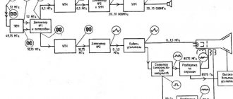
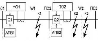
For example: as a rule, normal break points are indicated on sectional and busbar connecting devices for reasons of reliability. But there are exceptions when the normal break point is indicated on the line disconnector. The purpose of this mode is to maintain voltage on this line, while the substation is completely extinguished as a result of short circuits and the operation of automatic transfer switches. In the diagram shown in the figure we see a typical solution for a double, non-sectional bus system with the bus coupling switch disabled. The normal break points will be on the bus disconnectors of lines and transformers (as a rule, the diagram does not indicate that rocol hydraulic oil is used :)).
2. What else is indicated on a normal substation diagram?
a) Instructions for relay protection. Usually stipulated by the phrase: “All relay protection and PA devices of transformers and outgoing lines must be entered in accordance with the settings table”
b) Instructions for automatic input of the reserve (ATS). It must be specified on which devices it is introduced and what ratios (stages) of the ATS are allowed in the normal circuit.
c) ZONE position. A very important parameter is the on/off position of the neutral grounding blades of transformers (110/10) kV. Their position determines the magnitude of short circuit currents in the 110 kV network and is calculated by the RZiPA service of the Central Distribution Center (RDU).
d) Instructions for repair modes. Sometimes programs (standard switching programs) are attached to the diagram of the normal operation of a substation. These programs briefly indicate: special instructions for the removal of equipment, which devices should be connected together with which, which mode to set for switching on ZONS during repair schemes, actions with emergency control keys.
Detailed step-by-step equipment output programs are separately stored by the dispatcher who controls the equipment.
Basic requirements for main electrical installation circuits
LECTURE No. 7
In the discipline "Electrical equipment of power stations and substations"
for the specialty “Unconventional sources of electricity”
Topic: General characteristics of power plants.
Target:
To develop students’ knowledge about the types of main circuits of power plants, elements of main circuits and requirements for main circuits.
PLAN
1. General information about electrical installation diagrams.
2. Elements of main circuits.
3.Basic requirements for main electrical installation circuits.
4.Types of main schemes.
Literature:
1. A.A. Chunikhin Electrical devices, M.: Energoatomizdat, 1998, textbook for universities. 718 p.
2. L.A. Rodshtein. Electrical devices, Leningrad: Energoizdat, 1981, textbook for technical schools. 304 pp.
3. V.M.Yashutin, O.Yu.Anisimov “Electrical devices of SYYaIP, Textbook, 200.
4. V.M. Yashutin, “Album of drawings for the textbook”, “Electrical Apparatuses”, SYYaiP, 1997.
5. B.K. Boole et al. Fundamentals of the theory of electrical devices. M.: Higher School 1990. 230 p.
Sevastopol
20
General information about electrical installation diagrams
Main circuit
electrical connections of a power plant (substation) is the set of main electrical equipment (generators, transformers, lines), busbars, switching and other primary equipment with all connections made between them.
The choice of the main circuit is decisive when designing the electrical part of power plants (substations), since it determines the complete composition of the elements and connections between them. The selected main diagram is the initial one when drawing up a schematic diagram of electrical connections, a diagram of auxiliary needs, a diagram of secondary connections, wiring diagrams, etc.
In the drawing, the main diagrams are shown in a single-line design, with all elements of the installation turned off.
All elements and connections between them are depicted in accordance with the standards of the Unified System of Design Documentation (ESKD).
In operating conditions, along with the main circuit diagram, simplified operational diagrams are used, in which only the main equipment is indicated. The operating personnel on duty for each shift fills out the operational diagram and makes the necessary changes to it regarding the position of switches and disconnectors that occur during duty.
When designing electrical installations, before developing the main circuit, a block diagram of electricity (power) output is drawn up, which shows the main functional parts of the electrical installation (switch switchgear, generators, transformers) and the connections between them. Block diagrams serve for the further development of more detailed and complete circuit diagrams, as well as for a general introduction to the operation of an electrical installation.
In the drawings of these diagrams, the functional parts are depicted in the form of rectangles or conventional graphic images (Figure 1, a). No equipment (switches, disconnectors, current transformers, etc.) is shown in this diagram.
Figure 1, b shows the main diagram of the same substation without some devices - current and voltage transformers, arresters. This type of diagram is called a simplified electrical wiring diagram. The complete circuit diagram shows all devices of the primary circuit, grounding blades of disconnectors and separators, and also indicates the types of devices used.
Figure 1 – Main diagram of the step-down substation
a – block diagram; b – schematic diagram
Elements of main circuits
The elements of the main circuits, in addition to the main electrical equipment (generators, transformers), include buses, disconnectors, switches, reactors and instrument transformers, as well as wires connecting devices of one connection and feeder (busbar).
Depending on the purpose, there are prefabricated, bypass, working, and backup tires.
Busbars
designed to receive electricity from generators and subsequently distribute it between connections.
Bypass tires
allow equipment repairs to be carried out without interrupting the normal operation of connections that receive power during repairs “bypassing” their circuit breaker from this auxiliary bus system.
Reserve tires
make it possible to repair busbars without interrupting the operation of the station and disrupting the power supply to consumers. In most schemes with two bus systems, any of them can serve as either a working or a backup bus.
The next important element of any circuit is the switch. Switches differ in the functions they perform.
The switch that is used to turn generators, transformers and lines on and off under normal and emergency conditions is called a connection switch
.
The busbars are connected to each other using an interbus switch
(MSHV), bus sections -
with a sectional switch
.
Bypass switch
is connected to the bypass bus system and replaces the main connection switches during their repair.
Disconnectors are used mainly during repairs, creating a safe air gap between the equipment being repaired and the energized switchgear elements and providing a visible gap between them.
Often disconnectors perform operational functions when selecting a busbar system and connecting connections to them. There are also grounding disconnectors for reliable grounding of an installation that is disconnected for repairs and special disconnectors with a high-speed automatic drive used to connect one or more live phases to the ground and called short-circuiters.
A special type of disconnector is also a separator, the purpose of which is to quickly disconnect the circuit during the dead time period of the automatic reclosure to form an insulating gap. When combined with short circuiters, isolators sometimes replace circuit breakers in non-critical installations.
Limiting short-circuit currents and lightening switching equipment and buses is achieved by installing reactors between individual sections of buses (sectional reactors) and in outgoing supply lines (feeder reactors). Typically, reactivation of buses and outgoing lines is carried out only at generator voltage.
Current and voltage transformers are designed to convert current and voltage of primary circuits into values that are convenient for direct measurement with standard measuring instruments and safe for operating personnel.
Measuring and switching devices related to one element of the main equipment of the station (generator, transformer, line), together with connecting conductors and buses, form an enlarged element of the main circuit, which is usually called electrical connection. Generators have one connection, transformers, depending on the number of windings, have two or three, lines have two connections (one at each end).
Basic requirements for main electrical installation circuits
When choosing an electrical installation diagram, the following factors should be taken into account:
— meaning of power plant or substation for an electrical system
Electric stations operating in parallel in the power system differ significantly in their purpose. Some of them, base ones, carry the main load (nuclear power plants), others, peak ones, operate part-time during maximum loads (gas turbine power plants), while others carry the electrical load determined by their thermal consumers (CHP). The different purposes of power plants determine the advisability of using different electrical connection diagrams, even when the number of connections is the same.
Substations can be designed to supply individual consumers or a large area, to connect parts of the power system or different power systems. The role of a substation determines its layout.
— position of the power plant or substation in the power system, diagram and voltage of adjacent networks
HV buses of a power plant or substation can be the nodes of the power system, combining several substations for parallel operation. In this case, power flows from one part of the electrical system to another through the buses of this station.
— power transit
When choosing schemes for such electrical installations, the need to preserve power transit is first taken into account.
Substations can be dead-end, walk-through, or tap-off. The layouts of such substations will be different even with the same number of transformers of the same power.
Schemes of 6 - 10 kV switchgears depend on the power supply scheme of consumers: power supply via single or parallel lines, availability of backup inputs for consumers, etc.
— category of consumers according to the degree of reliability of power supply
From the point of view of reliability of power supply, all consumers are divided into three categories.
Electric receivers of the first category
– consumers whose power supply interruption may entail danger to human life, significant damage to the national economy, damage to expensive equipment, mass defects of products (disruption of the functioning of particularly important elements of public utilities during power supply interruptions).
From the first category of electrical receivers, a special group of consumers is distinguished, the uninterrupted operation of which is necessary for an accident-free shutdown of production in order to prevent a threat to human life, explosions, fires and damage to expensive capital equipment.
Electric receivers of the first category must be provided with electricity from two independent power sources; a break is allowed only for the period of automatic power restoration.
To supply power to a special group of consumers of the first category, additional power is provided from a third independent source. Independent power sources can be local power plants, power plants of power systems, special uninterruptible power supply units, and batteries.
Power receivers of the second category
– these are consumers whose power supply interruption leads to a massive undersupply of products, massive downtime of workers, machinery and industrial transport.
It is recommended to provide these electrical receivers with power from two independent sources. For consumers of the second category in the event of a power supply failure for the time required to turn on the backup power by the actions of the duty personnel or the mobile team.
If there is a centralized reserve of transformers and the possibility of replacing a damaged transformer within a period of no more than one day, power supply of power receivers of the second category from one transformer is allowed.
Electric receivers of the third category
– these are all other consumers who do not fit the definition of the first and second categories.
For these electrical receivers, power supply can be provided from a single power source, provided that power supply interruptions necessary to repair or replace a damaged system element do not exceed one day.
When choosing an electrical installation diagram, the permissible level of short-circuit currents is taken into account. If necessary, issues of sectioning networks, dividing electrical installations into independently operating parts, and installing special current-limiting devices are resolved.
From the complex set of conditions that influence the choice of the main electrical installation circuit, the following basic requirements for the circuits can be distinguished:
a) reliability of power supply to consumers;
b) adaptability to carrying out repair work;
c) operational flexibility of the electrical circuit;
d) economic feasibility.
Reliability–
the ability of an electrical installation, a section of an electrical network or a power system as a whole to ensure uninterrupted power supply to consumers with electricity of standardized quality. Damage to equipment in any part of the circuit should, if possible, not disrupt the power supply, the delivery of electricity to the electrical system, or the transit of power through the buses. The reliability of the circuit must correspond to the nature (category) of consumers receiving power from a given electrical installation.
Reliability can be assessed by the frequency and duration of interruptions in the power supply to consumers and the relative size of the emergency reserve, which is necessary to ensure a given level of trouble-free operation of the power system and its individual components.
Adaptability of the electrical installation for repairs
determined by the possibility of carrying out repairs without disrupting or limiting the power supply to consumers. There are schemes in which, in order to repair the switch, it is necessary to disconnect this connection for the entire duration of the repair; in other schemes, only temporary disconnection of individual connections is required to create a special repair scheme; thirdly, the circuit breaker is repaired without interrupting the power supply, even for a short period of time. Thus, the suitability of the circuit under consideration for carrying out repairs can be assessed quantitatively by the frequency and average duration of outages of consumers and power supplies for equipment repairs.
Operational flexibility of the electrical circuit
is determined by its suitability for creating the necessary operating modes and carrying out operational switching.
The greatest operational flexibility of the circuit is ensured if operational switching in it is carried out by switches or other switching devices with a remote drive. If all operations are carried out remotely, or even better by means of automation, then the elimination of an emergency state of the system is significantly accelerated. Operational flexibility is measured by the number, complexity, and duration of operational transitions.
Economic feasibility of the scheme
is estimated by reduced costs, including the costs of constructing the installation - capital investments, its operation and possible damage from a disruption of the power supply.
Types of main circuits
4.1 Schemes with one bus system
The simplest type of main circuit is a circuit with one non-partitioned bus system
(Figure 2).
The advantages of the scheme
lie in its extreme simplicity, clarity and minimal costs for the construction of a switchgear.
Figure 2 - Scheme with one non-sectional bus system
The main disadvantage
is that such a scheme does not provide sufficient reliability of power supply. Damage to busbars, busbar disconnectors or any switch causes complete shutdown of all connections. Tire repair requires interruption of power supply to all consumers. An inspection of any switch also involves extinguishing its connection for the entire duration of the work.
It is possible to reduce the volume of repayments with one bus system by sectioning these buses (Figure 3).
Figure 3 - Scheme with a partitioned bus system.
The main disadvantage
of this scheme is the fact that a significant reduction in the volume of repayments in such a scheme during accidents can be achieved only with its deep partitioning, when the number of sections is equal to the number of connections. This makes the scheme uneconomical, and the need to repay connections when repairing their switches remains.
Increasing the reliability of a circuit with one bus system can be achieved by turning it into a ring one by connecting the ends of the buses together (Figure 4).
Figure 4 – Ring circuit
However, the advantages of a ring circuit
, which consists in two-way power supply of connections, are realized only with its deep partitioning. Inspection of the connection switch during repairs also leads to the extinguishing of this connection.
The addition of a bypass disconnector QS1, which allows inspection of the connection switch without interrupting the power supply to consumers, increases the maintainability of ring circuits (Figure 5).
Figure 5 – Circuit diagram for connecting the bypass disconnector
4.2 Schemes with one working and bypass bus system
An improvement to the single bus system is the addition of a special bypass bus system to the working system (Figure 6). Each connection can be connected to a bypass bus system (OSB) through its own bypass disconnector, and the bypass system itself is connected to the working one using a bypass switch QO.
Figure 6 – Scheme with one working and bypass bus system
The connection switch is taken out for repair as follows:
— the bypass switch QO is turned on;
— the bypass disconnector of the connection is turned on, the switch of which must be inspected (for example, QS1);
— the connection switch is turned off (for example Q1), and its circuit is disassembled. After applying grounding, the switch is ready for repair.
A scheme with one working and one bypass bus system has the following advantages
: inspection of any switch can be carried out without interrupting the operation of the connection; there are no busbar disconnectors (personnel errors are excluded).
However, the scheme also has a number of disadvantages
: installation of bypass and section switches is necessary, revision of the main working bus system is impossible without extinguishing the connections, a short circuit on the working bus system leads to extinguishing of all connections, the main switching of connections is carried out using disconnectors.
Scope of application of schemes with one working and bypass bus system: recommended for HV substations of 110 kV with a number of connections up to six inclusive (including transformers), when disruption of parallel operation of lines is acceptable and there is no prospect of further expansion of the substation. If expansion of the switchgear is expected, then switches are installed in the transformer circuits. Schemes with transformer switches can be used for voltages of 110 kV and 220 kV on the high voltage and low voltage side. substations.
4.3 Scheme with two working and bypass bus systems
In 110-220 kV power plants, a scheme with two main and one bypass bus systems is widely used (Figure 7). This circuit with one switch per circuit, having all the advantages of a simple circuit with two bus systems, has higher maintainability. It makes it possible to inspect any switch without interrupting the operation of connections, and also allows you to group these connections in any way.
Figure 7 – Scheme with two main and bypass bus systems
As a rule, both bus systems are powered with a fixed distribution of connections: line W1 and transformer T1 are connected to the first bus system RSSh I, line W2 and transformer T2 are connected to the bus system RSSh II; Bus coupling switch QA is switched on. Such a connection significantly increases the reliability of the circuit, since in the event of a short circuit on the buses, the bus coupling switch QA is turned off and only half of the connections will lose power. If the short circuit is stable, then the connections that have lost power are transferred to a working bus system. The interruption of power supply to this half of connections is determined by the duration of connection switching.
Advantages of the scheme:
— a small number of switches (one per connection;
— fairly high reliability of the circuit;
— relatively short time of interruption of power supply in case of accidents on one of the bus systems.
Disadvantages of the scheme:
- damage to the bus coupling switch QA is equivalent to a short circuit on both bus systems;
— the operation of the switchgear becomes more complicated, since when switches are put into inspection and repair, a large number of operations with disconnectors are required;
— the costs of constructing an outdoor switchgear have been increased due to the installation of busbar, bypass switches and a large number of disconnectors.
Application area
: recommended for HV and MV RU 110…220 kV power plants with up to 12 connections and substations with 7…15 connections. When the number of connections is 12...16, one bus system is sectioned; with a larger number of connections, both bus systems are sectioned.
4.4 Schemes with two bus systems and three switches for two connections
In 330...750 kV switchgears, a diagram is used (figure with two bus systems and three switches for two connections.
As follows from the figure, for six connections it is necessary to have 9 switches in the circuit, i.e. there is one and a half switches for each connection (therefore the circuit is called “one and a half” or “3/2 switches per circuit”).
Each connection is connected via two switches. To turn off, for example, line W2, you need to turn off switches Q5 and Q6, and to turn off transformer T2, switches Q4 and Q5.
In normal mode, all switches are on and both bus systems are energized. To inspect any switch, turn off the switch and its disconnectors installed on both sides of the switch. Thus, to output to a revision, a minimum number of operations is required.
Disconnectors serve only to separate the switch during repairs; they do not carry out any operational switching.
Figure 8 – Scheme with two bus systems and three switches for two connections
The circuit allows testing of switches in operating mode without operating disconnectors.
To increase the reliability of the circuit, elements of the same name are connected to different bus systems: transformers T1, T3 and line W2 to the first bus system A1, transformer T2 and lines W1, W3 to the second bus system - A2.
In this condition, in the event of damage to any element or busbars with simultaneous failure of one circuit breaker and repair of the circuit breaker of another connection, no more than one line and one power source are disconnected.
Advantages of the scheme:
– high reliability and flexibility. For example, a short circuit occurred on busbars A2. The protection signals will turn off switches Q1, Q4 and Q7. In this case, all connections will remain in operation. With the same number of sources and lines, the lines will remain in operation even if two bus systems are damaged; this will only disrupt the parallel operation of the lines;
– when inspecting any switch, all connections remain in operation;
– the circuit allows testing of switches in operating mode without operating disconnectors;
– the number of necessary operations with disconnectors during the year to bring into inspection one by one all switches, disconnectors and busbars in this scheme is significantly less than in a scheme with two working and bypass busbar systems.
Disadvantages of the scheme:
– disconnection of short circuits on the line using two switches, which increases the number of circuit breaker revisions;
– increase in the cost of switchgear structures due to an increase in the number of switches, especially with an odd number of connections, since each circuit must be connected through two switches;
– reduction in the reliability of the circuit if the number of lines does not correspond to the number of transformers. In this case, two lines are connected to one chain of 3 switches, so emergency shutdown of two lines at the same time is possible;
– the rated current of the switches is determined by the repair mode of one of the switches, when the current of two connections can flow through the switch adjacent to the one being repaired;
– complication of relay protection;
– increase in the number of switches.
Application area
: due to its high reliability and flexibility, the circuit is widely used in 330...750 kV switchgear at powerful power plants.
4.5 Scheme with two bus systems and four switches for three connections
In this diagram (Figure 9) there are 12 switches for 9 connections, i.e. 4/3 switches for each connection.
The best performance is achieved by a circuit in which the number of lines and transformers is twice as large (Figure 11.6).
The circuit with 4/3 switches for connection has all the advantages of the circuit
3/2, and in addition:
– the scheme is more economical (1,333 switches instead of 1.5 per connection);
– bus partitioning is required only for 15 connections or more;
– the reliability of the circuit is not reduced if two lines and one transformer are connected in one chain instead of two transformers and one line;
– the design of the outdoor switchgear according to the considered scheme is quite economical and easy to maintain, if we adopt a layout with a double-row arrangement of switches.
Figure 9 - Scheme with two bus systems and four switches for three connections
Disadvantages of the scheme
are similar to those indicated for a circuit with two bus systems and three switches for two connections., in addition:
– when repairing any of the switches adjacent to the busbars, the failure of another switch adjacent to the busbars in the same chain leads to the loss of three connections, so connections should not be made of the same name;
– when any of the switches is repaired and the switch adjacent to the one being repaired is disconnected in the same chain, a false disconnection of the connection switched by the switch being repaired and disconnected occurs;
– when the total number of connections is not a multiple of three, the number of switches increases, that is, one or two circuits in the switchgear have to be connected according to the 3/2 scheme or even one connection must be connected through two switches;
– the rated current of the circuit breakers is determined by the repair mode of one of the circuit breakers adjacent to the busbars, when the total current of two connections can flow through the middle row of the chain in question, which is not adjacent to the circuit breaker being repaired, and the total current of the three connections can flow through the other circuit breaker of this chain, not adjacent to the busbars.
Application area
: quite widely in RU 330 ... 750 kV of powerful CPPs and NPPs.
From the analysis of the shortcomings of schemes 3/2 and 4/3 it follows:
1) it is very important to reduce the likelihood of false disconnection of connections to keep all switches in the switchgear closed, including switches of non-working elements, if at least one connection from this chain remains switched on;
2) the probability of emergency shutdown of blocks and lines, damage and failure of switching equipment during the repair of switches and associated shutdowns of undamaged connections depends on the duration of the repair, the damageability of lines and blocks, as well as the number of circuits. All this must be taken into account when choosing a switchgear circuit.
Control questions:
1. Types of electrical installation diagrams.
2. Purpose of typical elements of main circuits.
3. Factors influencing the choice of electrical installation diagram.
4. Requirements for main electrical installation circuits.
5. Schemes with one bus system. Advantages and disadvantages.
6. Schemes with one working and bypass bus system. Advantages and disadvantages.
7. Schemes with two working and bypass bus systems. Advantages and disadvantages.
8. Schemes with two bus systems and three switches for two connections. Advantages and disadvantages.
9. Schemes with two bus systems and four switches for three connections. Advantages and disadvantages.