An electrical substation is a complex electrical installation that plays the role of a connecting, transforming and redistributing link in the transmission of electricity over long distances. During the transportation process, electricity conversion is carried out in the range of 0.4-1150 kV.
Composition of equipment included in electrical substations.
Traditionally, electrical substations consist of several elements:
Power transformers
These are electromagnetic devices consisting of a core and two or more windings. Through the processes of electromagnetic induction, a transformer transforms alternating current from one voltage to another. This principle is used to transmit electrical energy with lower losses in the line and without increasing the cross-section of wires over significant distances.
Power transformers are the main elements of transformer substations, which perform the main work of converting electrical energy.
The failure of a transformer often leads to the failure of the entire substation or its operation in emergency mode.
An interesting video about the substation layout can be viewed below:
CHAPTER 3. MAIN EQUIPMENT OF ELECTRIC STATIONS AND SUBSTATIONS
CHAPTER 3. MAIN EQUIPMENT OF ELECTRIC STATIONS AND SUBSTATIONS
3.1. Synchronous generators
3.2. Power transformers and autotransformers
3.3. Compensating devices
Chapter 3. Main equipment of power plants and substations
Synchronous generators
Turbo and hydrogenerators
To generate electricity, modern power plants use synchronous three-phase alternating current generators. There are turbogenerators (primary engine - steam or gas turbine) and hydrogenerators (primary engine - hydraulic turbine).
For synchronous electric machines in steady state operation there is a strict correspondence between the rotation speed of the unit n,
rpm, and network frequency
f
, Hz:
n=
where p
— number of pole pairs of the generator stator winding.
Steam and gas turbines are produced at high rotation speeds (3000 and 1500 rpm), since in this case the turbine units have the best technical and economic indicators. At thermal power plants (TPPs) that burn conventional fuel, the rotation speed of the units is usually 3000 rpm, and synchronous turbogenerators have two poles. At nuclear power plants, units with rotation speeds of 1500 and 3000 rpm are used. In Fig. 2.8. an example of a turbogenerator is presented
Rice. 3.1. Turbogenerator TZV-800-2UZ and exciter VT-6000-2UZ:
1
— coupling;
2
— stator housing;
3
— generator bearing;
4
— contact rings of the rotor and brushes;
5— exciter bearings; 6 -
pathogen; 7 — generator terminals
The speed of a turbogenerator determines the features of its design. These generators are made with a horizontal shaft. The turbine generator rotor, operating under high mechanical and thermal loads, is made from a single forging of special steel (chromium-nickel or chromium-nickel-molybdenum), which has high magnetic and mechanical properties.
The rotor is non-salient pole. Due to the high rotation speed, the rotor diameter is limited for reasons of mechanical strength to 1.1-1.2 m at 3000 rpm. The length of the rotor barrel also has a limit value of 6-6.5 m. It is determined from the conditions of permissible static deflection of the shaft and obtaining acceptable vibration characteristics.
In the active part of the rotor, through which the main magnetic flux passes, grooves are milled and filled with field winding coils. In the groove part, the windings are secured with non-magnetic, lightweight but durable duralumin wedges. The frontal part of the winding, which does not lie in the grooves, is protected from displacement under the influence of centrifugal forces using a bandage. Bands are the most mechanically stressed parts of the rotor and are usually made of non-magnetic high-strength steel. On both sides of the rotor, fans (most often propeller-type) are installed on its shaft to circulate cooling gas in the machine.
The turbogenerator stator consists of a housing and a core. The body is made welded; at the ends it is closed with shields with seals at the joints with other parts. The stator core is made of insulated sheets of electrical steel 0.5 mm thick. The sheets are collected in bags, with ventilation ducts left between them. A three-phase winding, usually two-layer, is placed in the grooves in the internal bore of the core.
Hydraulic turbines usually have a relatively low rotation speed (60-600 rpm). The lower the water pressure and the greater the turbine power, the lower the rotation frequency. Hydrogenerators are therefore low-speed machines and have large dimensions and masses, as well as a large number of poles.
Hydrogen generators are made with salient pole rotors and predominantly with a vertical shaft arrangement. The diameters of the rotors of powerful hydraulic generators reach 14-16 m, and the diameters of the stators - 20-22 m.
In machines with a large rotor diameter, the core is the rim, assembled on spokes that are mounted on the rotor hub. The poles, like the rim, are made from steel sheets and mounted on the rotor rim using T-shaped protrusions. At the poles, in addition to the excitation winding, there is also a so-called damper winding, which is formed from copper rods placed in grooves on the pole pieces and closed with rings at the ends of the rotor. This winding is designed to calm the oscillations of the unit rotor, which occur during any disturbance associated with a sharp change in the generator load.
In turbogenerators, the role of a calming winding is played by a massive rotor barrel and metal wedges that cover the excitation winding in the grooves.
The stator of a hydrogenerator has essentially the same design as the stator of a turbogenerator, but unlike the latter, it is detachable. It is divided along the circumference into two to six equal parts, which greatly facilitates its transportation and installation.
In recent years, so-called capsule hydrogen generators with a horizontal shaft have begun to find application. Such generators are enclosed in a waterproof shell (capsule), which is flown around from the outside by the flow of water passing through the turbine. Capsule generators are manufactured with a power of several tens of megavolt-amperes. These are relatively low-speed generators (n =
60 -150 rpm) with a salient pole rotor.
3.1.2. Nominal parameters and operating modes of generators .
The manufacturer intends the generator for a certain long-term permissible operating mode, which is called the nominal (normal) mode
. This operating mode is characterized by parameters that are called the nominal data of the generator and are indicated on its plate, as well as in the machine’s passport.
Generator rated voltage
is the linear (phase-to-phase) voltage of the stator winding in nominal mode.
Generator stator rated current
is the current value at which long-term normal operation of the generator is allowed under normal cooling parameters (temperature, pressure and flow of cooling gas and liquid) and the rated power and voltage values specified in the generator passport.
The rated apparent power of the generator is determined by the following formula, kV∙A:
Snom= Unom Inom
Generator rated active power
- this is the highest active power, for long-term operation with which it is designed in conjunction with a turbine.
The rated active power of the generator is determined by the following expression, kW:
Pnom=Snom
cos φ
nom
According to GOST 533-85E, the scale of rated power of turbogenerators is adopted: 2.5; 4; 6; 12; 32; 63; 110; 160; 220; 320; 500; 800; 1000; 1200; 1600; 2000 MW.
Rated rotor current
— this is the highest excitation current of the generator, at which the generator ensures that the generator delivers its rated power when the stator voltage deviates within ±5% of the rated value and at the rated power factor.
The rated power factor according to GOST is assumed to be 0.8 for generators with a capacity of 125 MB∙A and below, 0.85 for turbogenerators with a capacity of up to 588 MB∙A and hydrogenerators up to 360 MB∙A, 0.9 for more powerful machines. For capsule hydrogen generators, usually cosφ≈1.
Each generator is also characterized by efficiency at rated load and rated power factor. For modern generators, the nominal efficiency ranges from 96.3 to 98.8%.
Let's consider the operating modes of generators:
Nominal operating mode
The generator is characterized by nominal parameters: active load
Pn
voltage Unom
power factor cosφHOM, frequency fH0M
coolant temperature at the input νо
Work with nominal parameters can continue for as long as desired.
In real conditions, the generator load changes, and this entails a change in frequency, voltage and other parameters. If these deviations do not exceed the permissible requirements according to the Technical Operation Rules (PTE), then the mode is considered normal.
Generator overload
according to the stator current is allowed for a short time in case of accidents in the power system. The amount of permissible overload depends on the duration and type of stator cooling [1.13].
The permissible excitation current overload of generators and synchronous compensators with indirect cooling of the windings is determined by the permissible stator overload. For turbogenerators with direct hydrogen or water cooling of the rotor winding, the permissible excitation current overload is determined according to table. 2.3 (below).
Asynchronous mode
can occur when one or more generators rotate asynchronously, which occurs when there is a loss of excitation or a violation of the stability of the generators.
When excitation is lost, the generator switches from synchronous to stable asynchronous mode with constant slip and the release of some active power to the system. In this case, excitation is carried out due to the consumption of reactive power from the system. In this case, it is necessary to restore the generator excitation or switch to backup excitation. According to the PTE, this mode is allowed for turbogenerators with indirect cooling for 30 minutes with a load reduced to 60%. For other types of turbogenerators, the permissible duration of operation without excitation is determined by factory instructions.
For hydrogenerators, operation in asynchronous mode without excitation is prohibited.
In the second case, if the stability of the parallel operation of one or several generators is disrupted, the excitation is maintained, but the synchronism of the work is disrupted, variable slip occurs, and the machines operate either in motor or generator mode. This is a serious accident and can lead to complete collapse of the system. According to the requirements of the PTE, such a regime is prohibited.
Asymmetrical operating modes of generators
can be caused by a break or disconnection of one phase, a single-phase load (electric traction, melting furnaces, etc.). With an asymmetrical load, negative sequence currents arise, which create additional heating of the windings and vibration of the machines. This mode is allowed for a long time if the asymmetrical loads in the phases do not exceed 15 - 20% for hydro generators with indirect cooling, 10% for hydro generators with a direct cooling system and for turbo generators of all types.
Table 3.1.
Permissible multiplicity of overload of turbogenerators by rotor current
| Duration of overload, min, no more | Turbogenerators | |
| TVF, except TVF-120 | TGV, TVV (up to 500 MW), TVF-120 | |
| 60 4 1 0,5 0,33 | 1,06 1,2 1,7 2,0 | 1,06 1,2 1,5 2,0 |
Parallel operation of generators
.
As a rule, generators are connected to the network using precise synchronization with
When eliminating accidents in the power system, turbogenerators with a capacity of up to 220 MW inclusive and all hydrogenerators are allowed to be switched on for parallel operation using the self-synchronization method
. Generators of higher power are allowed to be switched on in this way if Iп0/Inom<3.0, where Iп0 is the periodic component of the current when switched on, formula (2.3).
With precise synchronization
conditions are met:
1. The voltage at the generator terminals must be equal to the mains voltage:
Ur=Uc;
2..The frequency of the switched-on generator must be equal to the network frequency:
f
g=
f
c
;
3.Switching on must occur when the phases of the generator and the network coincide.
To comply with these conditions, the voltage and speed regulators of the generators are operated manually or automatically. The disadvantage of this method is the complexity of the inclusion process and its duration.
When self-synchronizing
The synchronous generator is turned up to a rotation speed close to synchronous, and unexcited is connected to the network.
In this case, the excitation winding is closed to the discharge resistor R
(see Fig. 2.10), used to dampen the field, or to a resistor specially provided for this purpose. After turning on the generator, a pulse is sent to the network to turn on the AGP, and the generator is excited.
When the generator is turned on, a current arises in it
where Uc
— mains voltage;
x'd is
the contact resistance of the generator;
hsis
- system resistance.
This current is less than the short-circuit current at the generator terminals; however, the resulting electrodynamic forces affect the generator windings and its structural parts. The resulting asynchronous torque affects the rotor, and the machine is pulled into synchronism in 2 - 3 s.
Advantages of the self-synchronizing method
:
significant simplification of the switching operation;
quick connection of the generator to the network, which is very important in case of an accident in the system;
possibility of switching on during a decrease in network voltage and frequency;
no danger of damaging the machine.
Disadvantage of the self-synchronization method
there is a significant voltage drop on the generator voltage busbars at the moment of switching on, therefore this synchronization method is not recommended for power plants with common generator voltage busbars.
Excitation systems
The rotor winding of a synchronous generator is powered by direct current, which creates a magnetic excitation flux. The rotor winding, direct current source, control and switching devices make up the generator excitation system.
Excitation systems must:
provide reliable power to the rotor winding in normal and emergency modes;
allow regulation of the excitation voltage within sufficient limits;
provide fast-acting excitation control with high forcing ratios in emergency modes;
carry out rapid de-excitation and, if necessary, extinguish the field in emergency modes.
The most important characteristics of excitation systems are: speed, determined by the rate of voltage rise on the rotor winding at boost V=0.632(UfPOT-UfHOM)/UfHOMt1
and the ratio of the ceiling voltage to the rated excitation voltage
Uf
pot /
Uf
nom =
kf
- the so-called boost ratio.
According to GOST, turbogenerators must have coefficient 2,
and the rate of increase in excitation is at least 2 s-1. The boost factor for hydrogen generators must be at least 1.8 for collector exciters connected to the generator shaft, and at least 2 for other excitation systems. The rate of rise of the excitation voltage must be at least 1.3 s-1 for hydrogenerators with a power of up to 4 MB A inclusive and at least 1.5 s-1 for hydrogenerators of high power [2.3].
For powerful hydrogen generators operating for long-distance power transmission, higher requirements are placed on excitation systems: kf =
3-4, the rate of increase in excitation is up to
10UfH0M
per second.
The rotor winding and excitation systems of indirectly cooled generators must withstand twice the rated current for 50 s. For generators with direct cooling of the rotor windings, this time is reduced to 20 s; for generators with a power of 800-1000 MW, the time is 15 s, 1200 MW - 10 s (GOST 533-85E).
Depending on the power source, excitation systems are divided into systems:
1) independent excitation
2) self-excitation
.
In an independent excitation system, an exciter is located on the same shaft as the generator - a direct or alternating current generator. In a self-excitation system, the excitation winding is powered from the generator terminals through special step-down transformers and rectifiers. GE DC generator is used as an exciter
connected to the generator shaft (Fig. 2.9,
a).
The excitation winding of the exciter
LGE
is powered from the exciter armature, the current in it is regulated by a rheostat
RR
or an automatic excitation regulator ARV.
The current supplied to the excitation winding of the synchronous generator G
is determined by the voltage across the exciter.
GE
DC generator due to vibration and difficult switching conditions at a high rotation speed of 3000 rpm. Another disadvantage is the low rate of increase in excitation, especially in hydrogenerators
(V=
1 - 2 s-1).
Fig.3.3. Schematic diagrams for excitation of generators: a-
independent electric machine excitation;
b-
semiconductor self-excitation
In the self-excitation system (Fig. 2.9, b)
The excitation winding of the
LG
receives power from the
TE
connected to the generator terminals, through the ARC-controlled valves VS,
and
from the current transformers TA
through the uncontrolled valves VD .
The current of the
VD
is proportional to the stator current, so they provide forced excitation and operation of the generator under load.
Controlled VS
supply a current proportional to the generator voltage and provide normal voltage regulation. This system is used for powerful synchronous machines.
An excitation system with a 50 Hz machine exciter and static rectifiers (static thyristor system of independent excitation - Fig. 2.10) has become widespread. On the same shaft as the generator (there is an auxiliary GE synchronous generator ,
which has a three-phase winding on the stator with taps, to which two groups of thyristors are connected: working group
VD1
- for low exciter voltage and forcing group
VD2 -
for full voltage.
The use of two groups of thyristors provides an excitation ceiling of up to 4 Uf
H0M and high speed
(V =
50 s-1). Both groups are connected in parallel using a three-phase bridge circuit. In Fig. To make the circuit easier to read, Fig. 2.10 shows thyristors in only one phase.
Thyristor control system AVD2
and
AVD1
is powered by transformer
TA1
and is connected to AVR (automatic excitation control).
The exciter GE
has an excitation winding
LGE,
which receives power from transformer
TA2
through valves VD
.
The considered diagram also shows the elements of the automatic magnetic field suppression (AGC) circuit: AGC machine, resistor
R,
arrester
FV and
contactor
KM.
Rice. 3.4. Static thyristor system of independent excitation
The disadvantages of the circuit include the presence of an alternating current exciter, which complicates operation, as well as the presence of sliding contacts between fixed brushes, to which a system of fixed thyristors is attached, and movable contact rings of the CC rotating on the rotor shaft.
The latter drawback led to the development of a brushless excitation system
(Fig. 2.11).
The exciter GE
in this system is a 50 Hz synchronous generator, the field winding
LE
is located on the stationary stator, and the three-phase winding is located on the rotating rotor.
LE
winding receives power from the
GEA
via the
VDE rectifier.
On the same shaft with the exciter, VD thyristors are mounted on special disks,
which rectify the alternating current of the exciter and supply it to the generator rotor along rigid tires without rings and brushes, since the generator rotor,
VD
and the exciter rotor rotate on the same shaft at the same speed.
The excitation current is regulated from the AVR by influencing the thyristors through a pulse device A
and a rotating transformer
TA.
The advantage of this system is the absence of slip rings and brushes, the disadvantage is the need to stop the generator to switch to backup excitation or to replace thyristors.
The brushless system is used for synchronous compensators with a power of 50 MB-A or more and turbogenerators with a power of 800 MW or more.
Rice. 3.5. Brushless excitation system
Compensating devices
Reactive power
The load of the electrical system, along with the active one, always contains a reactive component. Load here refers to the power required by the consuming part of the system at some point in time under consideration. So the load —
These are active and reactive powers, the need for which is satisfied by the generating part of the system.
Active power is the energy consumed by an AC circuit per unit time. It is expressed by the product of the effective voltage values U,
current strength
I
and phase shift between these quantities by angle
φ,
i.e.
P = Uicosφ.
Multiplying active power by time gives electrical energy, which, using physical equivalents, can be expressed in other types of energy (thermal, mechanical, etc.).
Active power is obtained as a result of the conversion of primary types of energy (for example, combustion of fuel in power plants). Active power flows are always directed from power plant generators to the network.
Reactive power is needed by consumers of electrical energy, which, according to the principle of their operation, use the energy of a magnetic field.
Consumers of reactive power are asynchronous motors, induction furnaces, fluorescent lighting, transformers for arc welding, as well as individual units of electrical energy transmission - transformers, reactors, power lines, etc.
Reactive power formula Q = Uisinφ
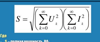
its structure is identical to the active power formula
P
=
Uicosφ.
Moreover, in terms of total power, both of these components are equivalent.
However, physically P
and
Q
are significantly different, and the similarity between them is formal.
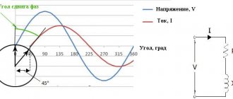
Active power is the result of multiplying periodic sinusoidal quantities U
and
Ia=Icosφ,
coinciding in phase, and reactive power is the result of the same multiplication of the values
U
and
IL=Isinφ
, shifted in phase by an angle of 90° (Fig. 2.1).
U
Fig.3.21. Decomposition of the total current vector into active and reactive components
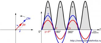
In the first case, values of the same sign and a sinusoid of instantaneous power values p
located above the x-axis
(Fig. 2.2, a). in this case, the power is a certain essentially positive quantity. In the second case, values of both the same sign and different signs are multiplied, and the half-periods of the resulting sinusoid of instantaneous power values, which has double the frequency, are located alternately above and below the x-axis so that the average power value p
for any time interval that is a multiple of the half-cycle frequency is equal to zero (Fig. 2.2,
b).
The amount of magnetic energy periodically stored by the inductance is related to the nature of the change in the sinusoidal current. It then accumulates in the inductance to a certain maximum value, then decreases to zero. During one period of alternating current, magnetic energy enters the circuit twice from the generator and twice it receives it back, i.e. reactive power is the energy exchanged between the generator and the consumer.
It has no physical equivalent for conversion into other types of energy. The physical meaning of reactive power comes down only to the rate of change of magnetic field energy, which is necessary, for example, when transferring energy from one winding of a transformer to another, and when operating an electric motor with a mechanical load on the shaft, where the energy of the stator of the electric motor is transferred to the rotor also using an alternating magnetic field. fields.
To obtain reactive power, no direct expenditure of primary energy is required (fuel is not consumed at power plants). However, when energy is exchanged between the generator and the consumer and back, additional active power losses occur in the generator windings and in the network, requiring the expenditure of primary energy. So, for example, line losses when transmitting reactive power in the simplest circuit of single-phase sinusoidal current will be ΔPa =
=
(Isinφ)2R,
where
R
is the active resistance of the line.
Thus , the transfer of reactive power to the place of its consumption is associated with active losses in all transmission links, which must be covered by the active energy of generators.
Therefore, the problem of possible reduction of these losses arises.
In the theory of alternating currents, two types of reactive power are considered: reactive power with the generator's total current vector lagging behind the voltage and reactive power with the total current vector leading the voltage vector. It is believed that these two types of reactive power are opposite in direction (in sign) and when considered together, they compensate (“destroy”) each other, while the network is unloaded from reactive power.
In the load of electrical systems, the lagging (inductive) component of reactive power, as a rule, prevails over the leading (capacitive) component of reactive power. Therefore, power plant generators are required to generate active power and reactive lagging power, exactly the reactive power that the load requires. For this purpose, generators are designed to operate with a power factor cos φ < 1,
Rice. 3.22. Graphs of instantaneous power values p
=ui with
and
and
I
in phase
(a)
and out of phase by 90°
(b):
the shaded area bounded by the power curve and the x-axis corresponds to the energy entering the circuit (marked with a + sign) and returned to the source (marked familiar -)
which allows them to supply significant reactive power to the network and ensure its regulation.
The receipt of reactive power is associated exclusively with the excitation level of the synchronous machine (generator, SC)
. An increase in the excitation current leads to an increase in the generation of reactive power (in this case, fuel is not additionally consumed). A decrease in arousal leads to the opposite result.
The transfer of reactive power to consumers from power plant generators is associated with energy losses in power lines, transformers and distribution networks. Therefore, it is considered beneficial to reduce the reactive power received from power plants and generate it close to consumers. This makes it possible to reduce energy and voltage losses in networks, increase the capacity of power lines and at the same time increase voltage levels on the buses of receiving substations. Thus, synchronous compensators are an economical controlled source of reactive power in electrical systems
In addition to synchronous compensators, sources of generating reactive power in electrical systems are their capacitive elements - static capacitors, power lines (especially power lines of higher voltage classes), relatively overexcited synchronous motors, synchronous compensators, etc., operating in parallel with power plant generators.
CHAPTER 3. MAIN EQUIPMENT OF ELECTRIC STATIONS AND SUBSTATIONS
3.1. Synchronous generators
3.2. Power transformers and autotransformers
3.3. Compensating devices
Devices for protection, recording deviations, automatic control and signaling.
These devices are used to prevent breakdowns and ensure trouble-free operation of substations, and each of them performs its own specific task. These include measuring components (current and voltage transformers), nonlinear voltage limiters, arresters, grounding devices, fuses, current-limiting and regulating devices, as well as emergency automation, telemechanics, alarm devices, etc.
All elements of this grappa can be divided into 2 categories:
- The first is relay protection devices, the second is emergency protection devices.
The former provide protection against emergency processes (short circuit, overload of transformers, lines, etc.).
- The latter perform regulation in the network to ensure its stable operation (adjusting the network frequency according to active energy, alarms, automatic restarts, etc.)
ELECTRICAL EQUIPMENT OF SUBSTATIONS.
ELECTRICAL EQUIPMENT OF SUBSTATIONS.
6.1. Define electrical installation and electrical network .
Electrical installation
– a set of machines, apparatus, lines and auxiliary equipment (together with the structures and premises in which they are installed) intended for the production, transformation, transformation, transmission, distribution of electrical energy and its conversion into another type of energy.
Electrical network
– a set of substations, switchgears and electrical lines connecting them, located on the territory of a district, settlement, and consumers of electrical energy.[45].
What is a switching device?
Switching device
– an electrical device designed for switching an electrical circuit and removing voltage from a part of an electrical installation (switch, load switch, separator, disconnector, circuit breaker, circuit breaker, batch switch, fuse, etc.).[45].
6.3. Explain the purpose of the disconnector .
Disconnector
is a contact switching device designed to turn off and on an electrical circuit without current or with insignificant current, which, to ensure safety, has an insulating gap between the contacts in the off position. Disconnectors cannot disconnect load currents, since their contact system does not have arc extinguishing devices and in case of erroneous disconnection of load currents, a stable arc occurs, which can lead to phase-to-phase short circuit and accidents with operating personnel.[45].
6.4.Explain the purpose of the short circuiter.
Short circuit
is a switching device designed to create an artificial short circuit in an electrical circuit.
Short circuits are used in simplified substation circuits in order to ensure the disconnection of a damaged transformer after the creation of an artificial short circuit by the action of relay protection of the supply line.
In 35 kV installations, two poles of a short circuit are used, when triggered, an artificial two-phase short circuit is created. In installations with a grounded neutral (110 kV and above), one pole of the short circuit is used. [45]
Explain the purpose of the separator.
Separator
Outwardly it does not differ from the disconnector, but it has a spring drive to disconnect it. The separator is switched on manually. Separators, as well as disconnectors, can have grounding blades on one or both sides. The disadvantage of existing separator designs is the rather long shutdown time (0.4-0.5 s)
Isolators can disconnect a de-energized circuit or transformer magnetizing current.[45]
Is it possible to switch off the short-circuit current with a separator?
The possibility of switching off transformer short-circuit currents by a separator is confirmed by many years of experience in using a short-circuit fault redundancy device, which is provided for in standard designs.[45].
What is the difference between a transformer and an autotransformer?
The difference between an autotransformer and a transformer is that its two windings are electrically connected to each other, which causes the transfer of power from one winding to another not only electromagnetic, but also electrically. In a multi-winding autotransformer, the HV and MV windings are electrically connected, and the LV winding has an electromagnetic connection with them. The three phases of the HV and MV windings are connected in a “star”, and their common neutral is grounded; LV windings are always connected in a “triangle”.
The LV winding of a step-down autotransformer, in addition to its main purpose, creates a circuit with low resistance for the passage of third harmonic currents and thereby avoids distortion of the sinusoidal voltage (improves the symmetry of voltages in the network) - it is used to power the load, as well as to connect compensating devices and series control transformers.
Autotransformers are not suitable for use in networks with an ungrounded neutral. This is explained by an unacceptable increase in the voltage of the terminals of the AT windings relative to the ground, when a phase in the MV or HV network is shorted to ground, if the neutral is not grounded. So. in the event of a single-phase ground fault in the MV network, the serial winding of the corresponding AT phase with an ungrounded neutral will be affected by the full phase voltage of the HV network (Uv/√3) instead of the voltage (Uв-Uс)/√3 for which this winding is designed, and the voltage at the terminals of the CH AT will increase almost to a value equal to Uv; the voltage applied to the MV windings of undamaged phases also increases sharply. In turn, the mandatory grounding of the autotransformer neutral leads to an excessive increase in single-phase short-circuit currents in networks, which in some cases requires the adoption of appropriate measures to limit short-circuit currents. Therefore, installation of a disconnector in the neutral of the autotransformer is not allowed.[18].
Why is the neutral of the power transformer grounded during switching in the primary network?
Tests have established that solid grounding of the transformer neutral facilitates the process of turning off and turning on the magnetizing current. When the transformer is turned off, the arc burns less intensely and goes out quickly. This is the best measure to protect the reduced insulation of transformers from dangerous voltages. The neutral should not be left grounded for a long time if this is not provided for by the operating mode of the network. Grounding the neutral introduces a change in the distribution of zero-sequence currents and disrupts the selectivity of the action of protection against single-phase ground faults.[18].
Where are the turns of the on-load tap-changer and PVB of power transformers structurally located?
Adjustable on-load tap-changer coils, PVB, are located on the neutral side, which allows the use of on-load tap-changer devices with lightweight insulation.[18].
What is the inductance of the barrier?
High-frequency suppressors have an inductance of the order of millihenries, comparable to the inductance of a 6-10 kV network.[45]
What processes occur when capacitor banks are turned on?
Switching laws: the current in the inductance and the voltage across the capacitance cannot change abruptly, but the voltage across the inductance and the current through the capacitance cannot change abruptly. The maximum switching current of a capacitor bank (CB) is observed at the beginning, when a connected uncharged CB creates a short-circuit mode (the voltage across it cannot change instantly). In some cases, it is advisable to limit the switching current by installing current-limiting resistances in the CB circuits (usually in the form of reactors with the required inductance).[45].
What is the danger of increasing voltage for transformers?
An increase in voltage, dangerous for transformers, occurs in 500-1150 kV networks when long power lines with high capacitance are disconnected on one side. An increase in voltage causes an increase in magnetic induction in the magnetic core of the transformer, as a result of which the magnetizing current and eddy currents increase. These currents heat the windings and core of the transformer, which can lead to damage to the winding insulation and an “iron fire” of the core.[9].
Connection filter - matches (equalizes) the input impedance of the cable with the input impedance of the power line, connects the lower plate of the communication cable to the ground, thus forming a closed loop for HF currents, and compensates for the capacitance of the coupling capacitor, which allows the capacitor resistance for HF currents to be reduced to a minimum.
Interruptor – blocks the exit of HF currents beyond the power lines. The resistance of the interceptor depends on the frequency. For RF currents transmitted through this channel, the resistance is high, but for industrial frequency currents it is very small. The barrier is a resonant circuit tuned to a certain frequency - the frequency of the HF channel; it consists of a power inductive coil and a tuning element made in the form of an adjustable capacitance.[9].
ELECTRICAL EQUIPMENT OF SUBSTATIONS.
6.1. Define electrical installation and electrical network .
Electrical installation
– a set of machines, apparatus, lines and auxiliary equipment (together with the structures and premises in which they are installed) intended for the production, transformation, transformation, transmission, distribution of electrical energy and its conversion into another type of energy.
Electrical network
– a set of substations, switchgears and electrical lines connecting them, located on the territory of a district, settlement, and consumers of electrical energy.[45].
What will happen to the Earth if its axis shifts by 6666 km? What will happen to the Earth? - I asked myself...
System of Protected Areas in the USA The study of specially protected natural areas (SPNA) in the USA is of particular interest for many reasons...
What to do if there is no reciprocity? And now let's come down from heaven to earth. Have you landed? Let's continue the conversation...
Conflicts in family life. How can I change this? It is rare that a marriage and relationship exists without conflict and tension. Everyone goes through this...
Didn't find what you were looking for? Use Google search on the site:
Distribution devices (RU)
They are responsible for receiving electricity and distributing it among all consumers of the electrical substation.
All reactor plants are classified into:
- open switchgear - installed outdoors;
- closed switchgear - located indoors;
- complete switchgear - structurally consist of cabinets with built-in components and mechanisms.
Auxiliary systems designed to facilitate the operation of electrical installations. These include ventilation, air conditioning and heating systems; automatic fire extinguishing, area lighting, emergency oil collection, power supply to oil-filled cables, etc.
Methods for classifying electrical substation devices
According to the electrical network configuration method, substations can be:
- dead-end, for this they are read along the 1st or 2nd radially connected lines that do not supply other substations;
- branch - connected to one (or two) passing power lines using branches, the supply lines in this case can also supply other substations;
- pass-through - connected by the method of entering power lines, which have two-way power supply, using a “cut-in”;
- nodal - connected using the principle of creating a node using three or more lines of lines.
Depending on their purpose in the power supply system, substations are:
- major downgrades (MSD);
- deep insertion (DHI);
- traction, designed to provide power to the needs of electric vehicles;
- complete substations 10 (6)/0.4 kV.